Jack Riley produced variants of the Cessna 310 to improve performance. The Riley Rocket 310 and the Riley Turbostream 310 replaced the standard Continental 310 hp (230 kW) engines with Lycoming TIO-540 350 hp (261 kW) engines. These turbocharged intercooled engines were installed with three-blade Hartzell propellers in a counter-rotating configuration to further increase performance and single-engine safety. At 5,400 lb (2,400 kg) gross weight the aircraft had a weight to power ratio of 7.71 lb (3.50 kg) per horsepower. This resulted in a cruising speed of 260 knots (480 km/h) at 18,000 feet (5,500 m) and a 3,000fpm rate of climb.
The Riley 65 and Riley Super 310 conversions used Continental engines.
Variants:
Riley 65 Cessna 310 to 310G by fitting two 240-260 hp (179–194 kW) Continental O-470D/-470M engines.
Riley Super 310 Conversion of Cessna 310/320 by fitting two 310 hp (231 kW) Continental TSIO-520-J/-N engines.
Riley Turbostream Conversion of Cessna 310 by fitting two 350 hp Lycoming engines.
Riley Rocket Conversion of Cessna 310 by fitting two 290 hp (216 kW) Lycoming IO-540-A1A5 engines and more fuel.
Specifications:
Riley Super Turbostream / Cessna 310/320 Engines: 2 x Continental TSIO-520-J2BD, 350 hp Seats: 4/6 Wing loading: 30.73 lb/sq.ft Pwr loading: 7.9 lb/hp Max TO wt: 5500 lb Empty wt: 3600 lb Equipped useful load: 1601 lb Payload max fuel: 185 lb Range max fuel/ 75% cruise: 1235 nm/4.7 hr Range max fuel / 55% cruise: 1721 nm/ 7.7 hr Service ceiling: 36,000 ft 75% cruise: 260 kt 55% cruise: 225 kt Vmc: 82 kt Stall: 73-82 kt 1.3 Vso: 95 kt ROC: 3200 fpm SE ROC: 600 fpm @ 106 kt SE ceiling: 25,000 ft Min field length: 1400 ft Fuel cap: 1218/1416 lb
Riley Super 310, 320 / Cessna 310/320 Engines: 2 x Continental TSIO-520-J, 310 hp Seats: 4/6 Wing loading: 30.73 lb/sq.ft Pwr loading: 8.25 lb/hp Max TO wt: 5500 lb Empty wt: 3400 lb Equipped useful load: 1818 lb Payload max fuel: 600 lb Range max fuel/ 75% cruise: 1306 nm/5.1 hr Range max fuel / 55% cruise: 1644 nm/ 7.2 hr Service ceiling: 36,000 ft 75% cruise: 255 kt 55% cruise: 230 kt Vmc: 83 kt Stall: 67-76 kt 1.3 Vso: 87 kt ROC: 2200 fpm SE ROC: 500 fpm @ 106 kt SE ceiling: 24,000 ft Min field length: 1550 ft Fuel cap: 960/1218 lb
Jack Riley kept semi retiring between his aviation ventures, wanting to have only a small business, but was soon back in full force with the Riley Rocket. The Cessna 310 was fitted with under wing exhaust along with airfoil nacelles to house the 290¬hp Lycoming engines. Three blade props (among the first on light twins) were used, and extra fuel tanks extended the range. A one piece windshield and extended cabin area were also part of the conversion.
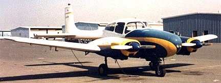
A 1953 Riley project was to convert the Navion to a twin. The Twin Navions started with two 140 hp engines and graduated to 150s and finally to 170s. He built 15 of the airplanes at his Fort Lauderdale, Florida facility, and 85 others for a total of 100 were built in Greenville, Texas, by Temco (later the “T” in LTV). Temco production of Riley Twin Navions was under a contract with Jack Riley, who handled sales, engineering, and tooling.
Planes were produced by both Riley and Temco on a production line basis in 1953-54, where the first 20 had 140hp Lycoming O-290-D2As, later 150hp 0-320s in larger cowlings as standard for all Twin Navions up to the introduction of the D-16A (or Riley 55).
In December 1953, Temco acquired the Riley Twin Navion program
In the summer of 1941, by order of Koku Hombu at the Rikugun Kokugijutsu Kenkyujo Army Aviation Research Institute, research began on the creation of a heavy twin-engine fighter. A team of specialists from several Japanese aircraft manufacturing companies was created at the institute. It was initially assumed that the new aircraft would be a single-seat long-range escort fighter. However, in July 1942, the design team was disbanded, and the engineers from its various companies were recalled to solve more urgent tasks.
It was decided to retask the machine as a heavy multi-purpose attack fighter designed for operations at low and medium altitudes and at the same time capable of hitting heavily armored ground and surface targets. To speed up work, several engineers from the 1st Army Aviation Arsenal located in Tachikawa were sent to the institute. Based on new tasks, it was decided to equip the aircraft with a cannon, large for aviation, 57-mm Ho-402 caliber, specially developed for this aircraft by Nippon Special Steel Dr. Masaya Kawamura.
The development of a new automatic gun, which received the designation No-402, went in parallel with the Ki-93 project. At the same time, Nippon Special Steel worked closely with Rikugun. The entire project of the attack aircraft was built around this gun, and the gun was created for the aircraft project. The No-402 cannon was located in a ventral gondola.
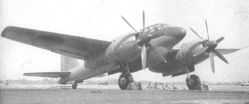
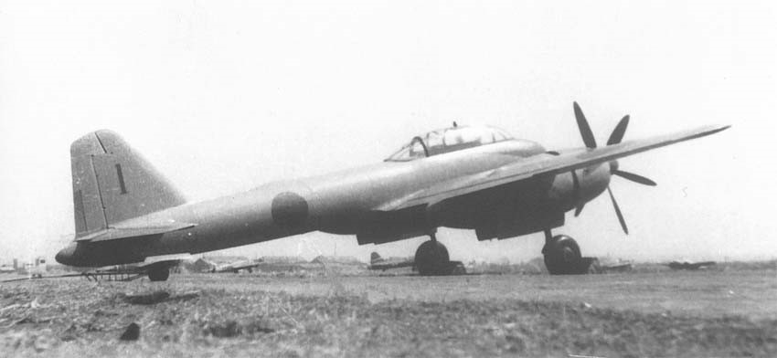
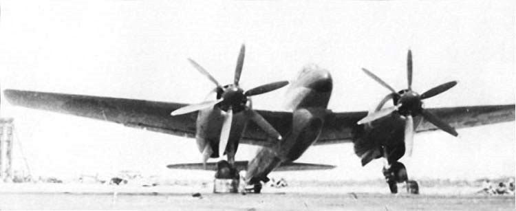
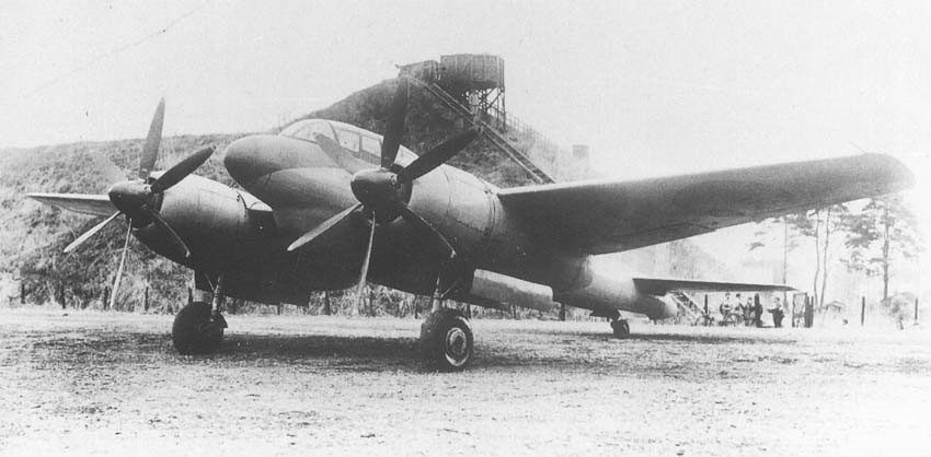
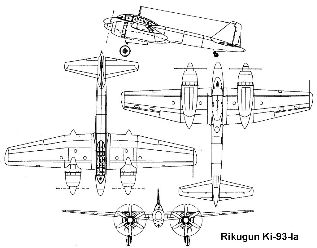
The Ki-93 was a low-winged monoplane of all metal construction, with the crew of two sitting in tandem under a canopy at the front of the fuselage, and a ventral gondola slung under the fuselage to accommodate large cannons. The wing was of laminar flow section.
On February 22, 1943, the new aircraft project was approved by Koku Hombu and received the designation Ki-93.
By the time the Ki-93 had already begun to take shape, the military situation in Japan was already very difficult. Japan suffered from the almost daily B-29 raids, and the US invasion of Japan loomed ever more clearly on the horizon. It was urgently necessary to seek means of fighting both the almost invulnerable B-29s and the anticipated Allied invasion fleet. As a result, the Ki-93 could become one and the other. When Rikugun Kokugijutsu Kenkyujo set about shaping the final look for the future Ki-93, the idea came up that the aircraft being designed could solve both anti-bombing and anti-ship missions equally well. In both cases, the aircraft had to be well protected in order to keep inevitable damage from both defensive fire of bomber machine guns and anti-aircraft artillery of ships. Therefore, it was supposed to build two versions of the Ki-93 in parallel. First, the Ki-93-I Co. is a heavy interceptor fighter. The second Ki-93-I Otsu is an anti-ship attack aircraft. Initially, it was planned to install Mitsubishi Ha-211 engines on the aircraft, but subsequently both models were equipped with two 18-cylinder air-cooled Mitsubishi Ha-214 engines, each of which developed 2,400 horsepower, for the most efficient removal of tremendous moment from engines equipped with six-bladed propellers 3.8 m in diameter
To ensure maximum survivability, the pilot was protected by five 12 mm armor plates. Two armor plates protected the cockpit in front, two on the sides and one on the back. Glazing of the cockpit was made of 70 mm bulletproof glass. The rear gunner was also protected by 12 mm of armor from the tail side of the aircraft. In addition, the fuselage fuel tanks were designed, had automatic fire extinguishing means, and were also protected by 8 mm armor. Each engine also had local armor protection. Defensive armament consisted of one 12.7-mm machine gun Ho-103, located in the rear of the cabin under the movable section of the flashlight. The difference in the two versions of the Ki-93 was the type of gun mounted in the lower gondola.
The Ki-93-I Co. was equipped with a 57-mm Ho-402 cannon with 30 rounds, reinforced with two 20-mm No-5 guns. It was expected that the 57-mm gun No-402 is capable of inflicting enough damage in one shot, guaranteed to destroy the B-29. But-402 had a rate of 80 rounds per minute, firing 2.7-kg shells with an initial speed of 700 m / s. For Ki-93-I Otsu, they provided weapons from the latest automatic 75-mm gun No-501, the total mass of which was 450 kg, the rate of fire reached 80 rounds / min, the initial projectile speed 500-550 m/s.
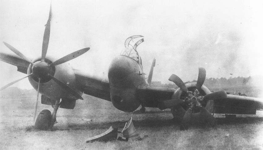
In addition to the Ki-93-I gun, the Otsu had to carry two 250 kg bombs. In the manufacture of prototypes, it turned out that it was not possible. This was due to a greater than expected weight of equipment. In order to somehow rectify the situation, the ammunition load of the No-402 gun had to be reduced from 30 to 20 rounds. Additional difficulties were brought by the undeveloped Na-214 engines, which lacked the declared power. As a result, the first prototype in the Ki-93-I Co. configuration was completed only in March 1945. On 8 April 1945 pilot Lt. Moriya of the Koku Shinsa-bu (Air Examination Department) with 2nd Lt. Ikebayashi in the second seat, first flew, from Tachikawa airport. During the tests, the armament was absent.
The first 20-minute flight turned out to be the last. When landing with too high landing speed, undershot the runway,and the left landing gear broke, resulting in severe damage to the left wing, prop, engine and landing gear. The only flight noted good controllability, good flight characteristics, and all on-board equipment worked flawlessly.
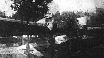
The prototype was returned to the factory for repair, which took four weeks. When the aircraft was ready for re-testing, an American bombing raid on the city of Tachikawa, completely destroyed the aircraft.
The second prototype Ki-93-I Otsu on the eve of the surrender of Japan was in the final stages of assembly.
After the raid on Tachikawa, it was evacuated to the Takahagi airfield in Saitama Prefecture, complete the assembly and make a test flight. Here, the incomplete prototype was captured by the Americans. After the war, he was taken to the United States as FE-152 at Middleton Air Material, where it was studied in September 1946. On 18 September 1946 was it was transported to Park Ridge, where all trace was lost after 1949.
Ki-93-Ia Engines: 2 × Mitsubishi Ha-214 1, 1,470 kW (1,970 hp) Propellers: 6-bladed VDM, 3.80 m (12 ft 6 in) diameter Wingspan: 19.00 m (62 ft 4 in) Wing area: 54.75 m2 (589.3 sq ft) Length: 14.215 m (46 ft 8 in) Height: 4.85 m (15 ft 11 in) Empty weight: 7,686 kg (16,945 lb) Gross weight: 11,440 kg (25,221 lb) Crew: 2 Guns: 1× 57 mm Ho-401 cannon in ventral gondola 2× 20 mm Ho-5 cannon in wing roots 1× 12.7 mm Ho-103 machine gun on flexible mounting in rear cockpit Estimated performance Maximum speed: 624 km/h (388 mph, 337 kn) at 8,300 m (27,200 ft) Cruise speed: 350 km/h (220 mph, 190 kn) at sea level Range: 3,000 km (1,900 mi, 1,600 nmi) Service ceiling: 12,050 m (39,530 ft) Time to altitude: 9 min 3 sec to 6,000 m (19,700 ft)
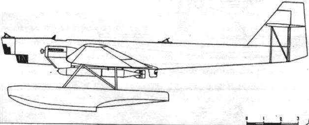
During his years in the USSR, French aircraft builder Paul Aimé Richard designed and built the Richard TOM-1 (Russian: Ришар ТОМ-1) Naval float bomber and torpedo boat. Only one prototype was built that was not produced due to the introduction of a navalized version of the Tupolev TB-1 with similar features and capabilities, but cheaper and easier to build.
The projecting task of the Open Sea Torpedo Boat or TOM was assigned to the KB led by Richard in late 1928. Several Soviet engineers participated in its development, who would soon achieve international renown for their creations. Notable among them were: II Artamonov, DM Jomnski, D. Samsonov, SA Lavochkin, IV Ostoslavski, MP Mogilievski, AL Gimmelfarb, GS Yelenievski, ZI Zhurbin, NI Kamov, MI Gurevich, SP Koroliov, IV Chetverikov, NK Skrzhinski, GM Beriev, IA Berlin, DA Mikhailov, VB Shavrov, GM Mozharovski, among others.
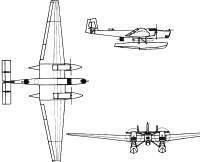
The TOM-1 was envisioned as a large monoplane of all-metal construction with floats. All the coating was made with smooth duralumin sheets of 0.5 – 0.6 mm, which gave it good aerodynamics. The structure was also designed entirely in duralumin, which was uncharacteristic of Soviet aircraft construction for those years.
The very thick wing with a 33 meter span had a rectangular midplane that was joined to consoles with a trapezoidal shape in the plane and marked narrowing towards the ends. The wing had a Sen-Sir-60 profile, with two skeletal spars and laminated ribs with large circular and oval holes to reduce weight. These ribs were located at a distance of 0.4 meters (quite compact for Soviet standards of the time). The segments of the stringer structure were achieved by joining two grooved pieces to form a kind of rectangular tube. Louvred flaps, capable of tilting downward at 40º angles, were located along the entire span of the trailing edge on the consoles.
The fuselage was a monocoque structure with the frames every 0.4 meters. The stringers were located every 150 mm, both in the fuselage and in the floats.
The tail unit was located high with triple empennage and was braced by means of N-pillars. The tail rudders incorporated trimmers to reduce the effort on the controls.
The large floats were fixed to the fuselage by means of 4 struts with tensioners between them.
The whole construction of the TOM-1 was quite light and very strong, but it was very technically demanding and expensive, almost twice that of the similar TB-1, and required a great deal of expensive sheets of duralumin, of which a considerable part was lost when drilling to reduce weight.
The two 680 hp BMW VI engines located on the wings.
The armament consisted of three firing points with PV-1 machine guns. These points were located fore and aft and a third in a retractable turret located in the lower section of the fuselage.
In the ventral zone, between the floats, one or two torpedoes could be fixed, developed by the OsTex Byuró.
The model was developed by the workshops located in the same KB building. On July 3, 1929 the project was completed and signed by PA Richard, his deputy DM Jomski and specialist SA Lavochkin.
In the fall of 1930, the plane was built and on January 1, 1931 it was transferred to Sevastopol for testing.
Assembly and preparation for testing were extremely lengthy. The plane was only ready in August. During the tests, carried out by pilot NI Kamkin with NI Kamov as engineer in charge, the aircraft presented acceptable performance. However, the new torpedo bomber was similar in capacity and performance to the TB-1 bomber and Tupolev was already successfully projecting a navalized version of this giant known as the ANT-4P. Building a similar plane, expensive and developed with unusual materials, was considered little objective. Only the prototype was built.
In 1931 Richard left the USSR due to the lack of new orders.
TOM-1 Engines: 2 x 680 hp BMW VI Wingspan: 38.00 m Length: 19.95m Wing area: 120.00 sq.m Empty weight: 5255 kg Normal takeoff weight: 8030 kg Top speed: 210km/h Cruising speed: 182 km/h Practical ceiling: 5500 m Armament: 3 x 7.62mm PV-1 machine guns Bombload: 1000 kg of bombs or two torpedoes Accommodation: 4-5
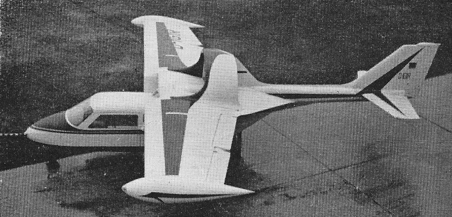
Since soloing in 1931, Bud Rich had owned and flown many aircraft, and frequently considered the advantages of continuing flight should one of two engines cut out. He put ideas and sketches down on paper.
At that time, Nelson Barnard Rich was instructing a course in practical-applications for aircraft students at M.I.T. He found three graduate students shared his enthusiasm for his basic plan for a twin-engine airplane. Soon, they were supplying the needed engineering. Bud provided materials, mechanical skills and space at his “Government Approved Aircraft Repair Station #226” at the Boston Airport.
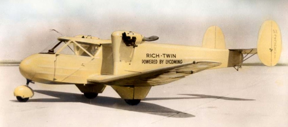
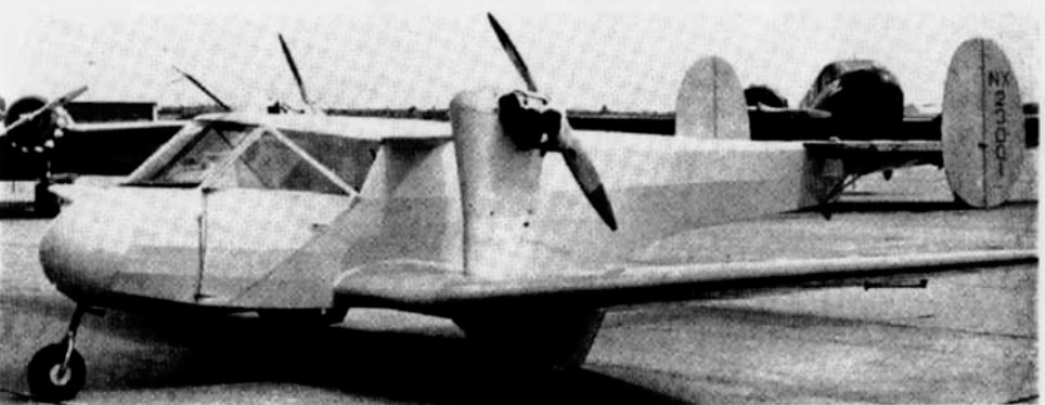
Those three young engineers were James (Jim) Kendrick (later with Lockheed); Holden (Bob) Withington (later V.P. of Boeing); and, in particular, William (Bill) Cook (also V.P. with Boeing and author of the incomparable book: “The Road to the 707”). The name “Rich-Twin” was given to it in Ohio by men from Lycoming who had generously provided its 75 hp engines and worked with Sensenich for efficient propellers. They had this name painted on the ship’s smooth, yellow fuselage when Bud and his wife Alberta (Berta) had flown it to Cleveland’s last Air Show before World War II.
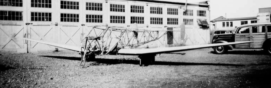
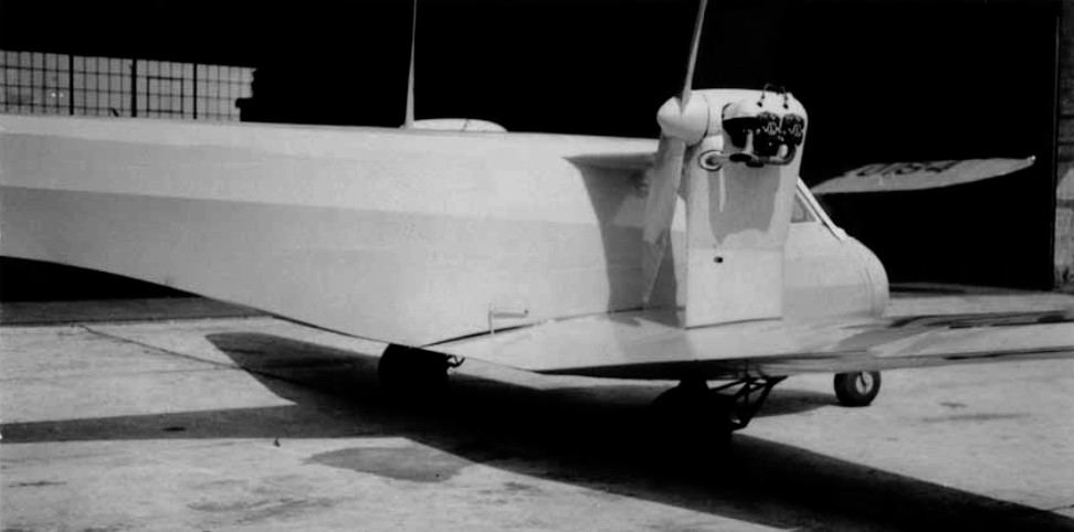
A low wing cantilever monoplane. the fuselage is a fabric-covered welded steel tube structure, with an enclosed cabin. Rectangular welded-steel framework fuselage covered with fabric. The cabin is in the nose of the fuselage seating two side-by-side with dual controls. Large entrance door on each side of the cabin. Baggage space behind seats. The wings are full cantilever, semi-monospar of plywood with rigid box spar and nose section, nine-foot wing flap with three positions. Tail Group; fabric covered welded steel tube structures, twin fins and rudders, tail plane braced by Vee struts. Landing gear; tricycle type, steerable nose wheel, partly retractable landing wheels. Plexiglas windshield.
A rectangular centre-section carries at its extremities two pylons for the engines, which are braced to the top of the fuselage longerons, and the main landing-wheel housings. Outer tapered wing sections. Wing structure of wood with two spruce and plywood box-spars and plywood covering. Single three position landing flap of duralumin construction under centre section.
Braced monoplane type tail unit with twin fins and rudders, Welded steel framework with fabric cover. Tricycle type undercarriage. Mainwheels enclosed in streamline housings, are semi-retractable. Goodrich tires. Steerable nosewheel. Oleo-pneumatic shock-absorber struts. Hayes hydraulic brakes.
Two engines mounted on welded chrome molybdenum steel-tube pylons, one on each side of the fuselage , at the extremeties of the centre-section and driving pusher airscrews.
Instruments: Compass, airspeed indicator, rate of climb indicator, sensitive altimeter, turn and bank indicator, electric clock, fuel pressure gauge and a standard group of engine instruments, including Waltham tachometers and oil gauges.
Test Flight – 1939 Bud presses RIGHT rudder pedal. The ship’s response begins another twisting summersault. This time Bud makes an immediate correction. He is aware that the airplane had tried to fall to the left. Close to laughing, he knows an answer is being revealed to him.
By pressing LEFT rudder pedal very lightly he is not surprised that his previously recalcitrant X-Ship responds immediately to correction of an attempted tumble to the right. No further tests are needed. It’s evident that the near fatal lack of control had occurred because during final checkup before the test flight, a trusted mechanic had too smartly thought that the fuselage interior’s carefully engineered CROSS-LINED control cables, should be more normally straight-lined. So, he changed – from correct to incorrect! Although now knowing that control cables are at fault, Bud faces the need to use right pedal for left turns, and left pedal for right turns. He manages an approach to landing, but is dismayed to have to abort it … a learning experience.
Far from easy, he again circles the airport, and is delighted with a short landing run due to its design incorporating one of the world’s first landing wheel on the nose. He taxies carefully back to the hangar. Many well wishers and reporters rush to greet him, but, scarcely noticing them, he immediately goes into the fuselage and returns the rudder cables to proper cross-line position.
Gasping surprise ripples through the onlookers as he re-enters the cockpit, starts the engines, taxies out on a runway and with notably short take-off run is again airborne.
Bud resumed his experimental airplane’s test flight. Comfortably circling the field twice, he landed with ease and taxied back to the relieved group of onlookers. This time he talks good-naturedly with them, expressing appreciation for their interest.
After Bud had successfully test-hopped it in April of 1939, it was featured in publications such as Janes, Aerosphere, Aero Digest, and others. All of their original blue prints and drawings have been preserved.
Bud passed on peacefully at home in Titusville, Florida on March 15, 1998.
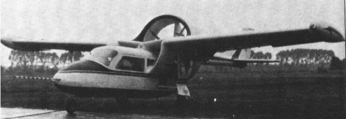
The Sirius 1 was developed to investigate the efficiency of the ducted fan as a means of propulsion for motor gliders. It was developed from the VFW FK-3 all-metal sailplane and was first powered by a Nelson 48 hp two-stroke engine, then by two Yamaha motor cycle engines and finally two 20 hp Fichtel & Sachs Wankel engines were chosen.
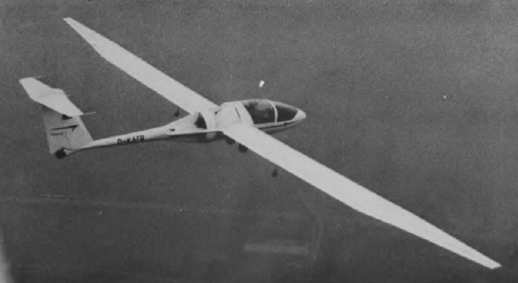
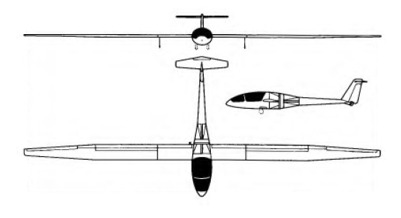
First flown in January 1972, the Sirius 2 is the two-seat companion to the Sirius 1, but Rhein-Flugzeugbau, the manufacturers, in this case have arranged with Caproni of Italy to use the wings, tail unit and landing gear of the A-21 Calif. This side-by-side two-seat ducted fan motor glider is powered by two 30 hp Wankel rotary engines which drive a ducted fan embedded in the fuselage just aft of the wing trailing edge. One engine is mounted in front of the fan and the other behind it. The fan shroud utilises an annular slat intake round the wing leading edge to keep the airflow attached to the duct, and suck-in doors fair off this intake when the power plant is not operating to maintain gliding performance.
Sirius 2 Engines: 2 x Wankel driving ducted fan Wing span: 20.38 m / 66 ft 10 in Length: 8.04 m / 26 ft 4.5 in Height: 1.8m / 5ft 11 in Wing area: 16.1 sq.m / 173 sq ft Wing section: Wortmann FX-67-K-170/60-126 Aspect ratio: 25.8 Empty weight: 510 kg / 1,124 lb Max weight: 690 kg / 1,521 lb Water ballast: None Max wing loading: 43.4 kg/sq.m / 8.88 lb/sq ft Max speed (powered): 146 kt / 270 km/h Stalling speed: 39 kt / 72 km/h Min sinking speed: 0.6 m/sec / 2 ft/sec Best glide ratio: 38 T-O run: 200 m / 656 ft Rate of climb: 120 m/min / 394 ft/min Range: 270km / 147nm
RFB built and flew the RF1 six-seat STOL transport in 1960, with two Lycoming engines geared to drive single pusher propeller in a wide-chord duct above the rear fuselage.
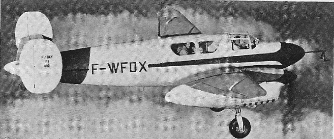
The R-1 was an experimental twin-engine monoplane with variable- incidence wings, first flown with normal wings on 16 December 1949, and with articulated wings in 1951.
Original patents taken out in 1938 and an aircraft built in 1940, but was destroyed during the war. Two prototypes were built, of wooden construction, powered by two Renault 6R engines.
The outer wing panels are articulated on an oblique hinge-line and these orientate automatically in turbulent air, the varying incidence absorbing the loads imposed.
Engines: two Renault 6R, 216 hp Wingspan: 43 ft 2.5 in Length: 30 ft 2 in Height: 11 ft 11 in Empty weight: 4950 lb Loaded weight: 6490 lb Max speed: 202 mph Time to 3280 ft: 4 min 10 sec Ceiling: 19,025 ft