The twin engined F.E.4, of which two were built in 1916, was intended to be a ground attack aircraft. To carry 1.5-lb. C.O.W. cannon. Other engines also fitted
Engine: 2 x 150-h.p. R.A.F.5
Span: 75ft 2in
Loaded wt: 5,988 lb
Speed: 84 mph
Seats: 3
The twin engined F.E.4, of which two were built in 1916, was intended to be a ground attack aircraft. To carry 1.5-lb. C.O.W. cannon. Other engines also fitted
Engine: 2 x 150-h.p. R.A.F.5
Span: 75ft 2in
Loaded wt: 5,988 lb
Speed: 84 mph
Seats: 3
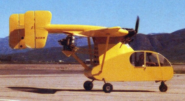
Described by its manufacturer as an “experimental ‘Three Passenger Airplane’ to demonstrate the high lift capability of an aircraft equipped with ‘Turbo Wing Technology.'” The Rotor Wing Ultra-Stol N25RW was developed in California in the late-1970s. It was reported as the Ultra-Stol by a company named Rotor Wing System and reportedly the aircraft flew at least twice.
Note the second engine and propeller, vertically mounted behind the trailing edge of the wing.
It had a relatively small wing and engines were reported as two Continental C85s and the rear could be tilted.
A very similar aircraft (maybe a rebuilt of the first?) was photographed in 1984 at Brown Field (near San Diego Ca), but it did not show a registration and was almost certainly never really completed. It differed in having a new wings, possibly from a Cessna Ce.150 and small canards. A company named High Technology Aircraft System, Inc (also in California). may be connected with this aircraft.

The Grasshopper 1 flew on March 11, 1962, but was considered to be underpowered. Only six months later the Grasshopper II emerged with two Walter Minor engines, and made its first hover on November 26 of that year. Its chief sponsor, F. G. Mitchell, died the same year and his heirs were unable to continue the financial support of the Grasshopper on their own.
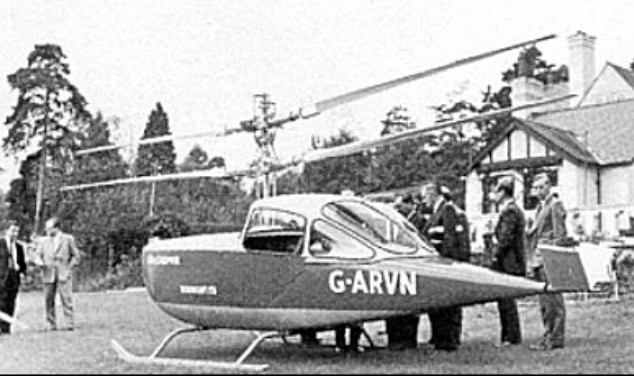
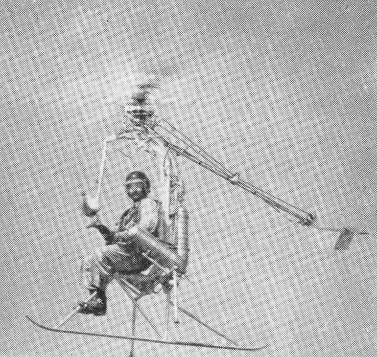
In 1951 J. S. Shapiro, formed a company, Servotec Ltd, to undertake R&D and contract design work for the aviation and light engineering industries. Shapiro had previously been with Sir Frank Whittle at Power Jets Ltd, where he came into contact with James Weir’s enthusiasm for personal helicopters. Aided by a loan from the Kemsley Flying Trust, Servotec began serious studies of small, foolproof helicopters and designed an experi¬mental model of the twin engined coaxial Grasshopper. These researches came to the notice of F. G. Mitchell, head of the Mitchell Engineering Group, who became fired with Weir’s and Shapiro’s enthusiasm.
Mitchell Engineering and Shapiro founded a new company in 1960, Rotorcraft Ltd, specifically to undertake the development of a helicopter which would embody the principles which had crystallised over the years. The construction was contracted to Servotec and two years later the company completed its first coaxial rotor helicopter, the Grasshopper 1.
The “Grasshopper” in its definitive form had an enclosed fuselage sports car with a small v-tail and a skid undercarriage. It was powered by a pair of 65hp Walter Mikron piston engines mounted forward of the two seat cabin. These drove a pair of two-blade coaxial rotors mounted on a pylon which emerged just ahead of the cockpit windshield.
G-ARVN, the prototype, flew on 11 March 1962, but was withdrawn from use the following spring when funding was withdrawn following the death of the owner of Mitchell Engineering, and the project was abandoned. It was considered to be underpowered.
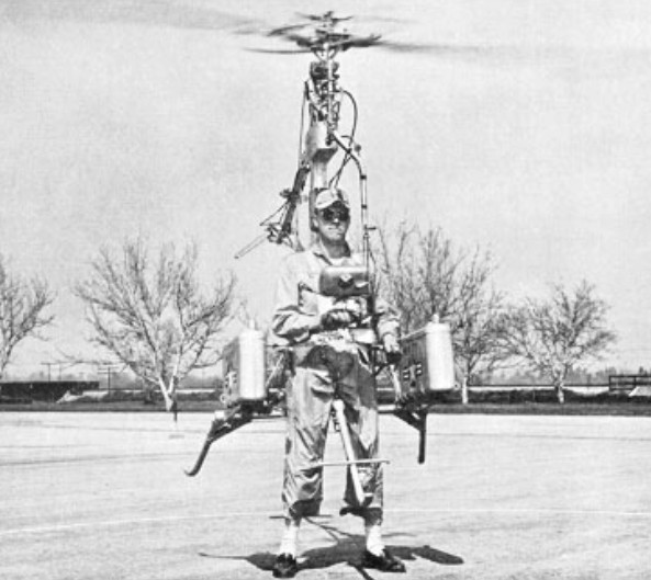
Little more heard of Gilbert Magill until the mid-1950s, when the RH-1 Pinwheel ‘strap-on’ personal helicopter appeared in 1954. The Rotorcraft RF-1 Pinwheel one-man helicopter was designed in 1954 to provide military personnel with a simple go-anywhere vehicle. Basically a strap-on device, it relied upon liquid propellants to power a tipjet at the end of each rotor blade, there thus being no rotor torque effect. The Pinwheel had a ‘quadripod’ frame layout, with the pilot sitting in the centre of the structure with a pair of liquid nitrogen tanks positioned behind him to feed Reaction Motors XLR-32RM rocket motors mounted at the rotor tips. A belt-driven rail rotor was incorporated in the simple and limited structure to provide steering capability.
Designed and built under US Navy contract, the RH-1 was extensively tested and made public demonstrations in 1955, leading to development of a similar Sky Hook military version. The capability of the Pinwheel can be measured by a maximum speed of 161km/h and ceiling of 4570m.

RH-1 Pinwheell
Engines: 2 x Reaction Motors XLR-32RM rocket
Rotors: 2-blade tip-powered main; 1-blade tail.
Empty weight: 100 lb
Cruising speed: 96km/h
Endurance: 9 min
Seats: 1

David Rose built the overpowered RP-4 for speed. The experimental counter-rotating propellers, inspired by a NASA project, run at 4800 rpm. Rose can connect both propellers directly to their engines without heavy reduction gearing. The props can change pitch for maximum efficiency at any speed. “It’s a drag-racer frame with skin on it to keep the wind out,” says Jerry Baer, a former pilot who helped Rose build RP-4.
Intended to compete in the Unlimited Class at the Reno Air Races, work began on the David Rose RP-4 project in 2005. Designed by Mr. Rose and built primarily be Eric Hereth, both of San Diego, at slightly over 4,600 pounds, 100 more than the minimum allowable, it was estimated that the racer would tour the course at upwards of 600 miles per hour, at least 100 mph faster than the then record holder.
Power is provided by two 600 cubic inch displacement V-8 engines designed originally for drag racing and, in that configuration, each is capable of producing as much as 2,500 horsepower (hp). Detuned to approximately 1200 hp. each, the engines were expected to withstand the rigors of running at full throttle for eight minutes, the time required to complete each heat at Stead Field in Reno.

The engines are mounted in tandem, each with its own independent systems, and each driving its own propeller. The engines are pressure-fed by two Pro-Charger F3-R centrifugal type superchargers with refrigerated intercoolers. The induction system is custom made from the 6” diameter throttle plate, to the attachment at the cylinder heads. The fuel is delivered by an electronic fuel injection system, also custom made for this application. Two-inch diameter stainless steel headers converge into collectors at the bottom of the fuselage exiting rearward and providing additional thrust in the process.
The contra-rotating propellers are reflective of those used in a ducted-fan experiment in the 1960s. Very efficient, but noisy, they split the job of delivering thrust and also cancel the negative torque reactions resulting from the P-factor, making such a high-power aircraft of small dimensions much more easily controlled.
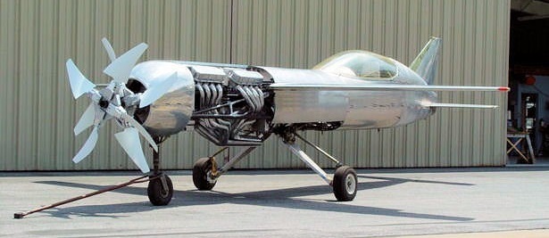
The racer employs a unique engine cooling system. To eliminate any unnecessary parasitic drag on the fuselage, all scoops typically found in this type application are absent. Water from the engine cooling jackets is directed through the wings in parallel tubing, while the wings themselves are filled with water. Heat is transferred from the tubing into the water and heat from the water is transferred overboard through the wing skins. The wing will hold about 50 gallons of water adding about 400 pounds to the weight of the aircraft, which will help it reach the unlimited class weight limit.
All custom crafted by Eric Hereth, the fuselage is 31 inches in diameter with the canopy protruding 12 inches above its top line. It is constructed of welded chromoly tubing, stressed for over 10 g’s and covered in aluminum sheeting. Spinner to tail the aircraft measures 28 feet, with a wingspan of 20 feet and a cord length of four feet at the root. Wing area is 58 square feet, resulting in a wing loading of nearly 100 pounds per square foot.
A change in the rules instituted by the Reno Air Racing Association (RARA) prevented the racer from completing in the unlimited category, and as a result, work on the nearly completed aircraft was halted in 2012.
The IMAM Romeo Ro.57, powered by two 840 hp Fiat A.74 R.C.38 radials, entered service in 1942 with home-based elements of the Regia Aeronautica.
A single-seater, it carried an armament of two 20mm cannon and two 112.7mm machine guns in the nose.
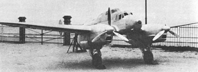
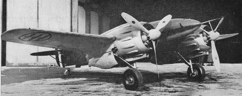
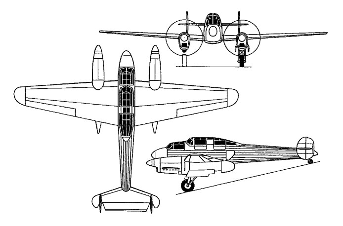
Designed for an October 1934 specification calling for a three-seat fighter to serve as an aerial command post for single-seat fighters, the R-110 was flown for the first time on 30 March 1938.
Of mixed construction, with plywood-covered wooden wings and a welded steeltube fuselage, the R-110 was powered by two 450hp Renault 12 Ro 2/3 12-cylinder air-cooled engines. Armament was two fixed 20mm cannon and a single 7.5mm machine gun on a flexible mount in the aft cockpit.
The R-110 was unusual in that the pilot and aircraft commander were seated behind separate vertically- staggered stepped windscreens. The competing Potez 630 had appeared in production form before the R-110 prototype entered flight test and further development of the latter was discontinued.
Max take-off weight: 3300 kg / 7275 lb
Empty weight: 2165 kg / 4773 lb
Wingspan: 12.80 m / 42 ft 0 in
Length: 9.66 m / 32 ft 8 in
Height: 3.37 m / 11 ft 1 in
Wing area: 24.00 sq.m / 258.33 sq ft
Max. speed: 470 km/h / 292 mph
Range: 1280 km / 795 miles

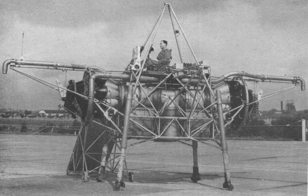
The Bedstead, officially called a Thrust Measuring Rig (TMR), was the brainchild of Doctor A.A.Griffith of Rolls Royce. It was a flat riser which hovered on the deflected exhaust gases of two Rolls Royce Nene jet engines. Compressed air nozzles provided directional control. The data gathered during the Bedsteads’ test programme in the mid 1950s led to the development of a special turbojet engine for jet lift, the RB108.
This was a radically new approach towards the development of vertical take off aircraft. Basically it consists of a tubular frame, said to measure about 20 ft. across, on which are mounted two Nene engines having a common, downward facing tail pipe. Space is also provided for fuel tankage and the pilot is seated in the normal attitude on the top.
The weight amounts to some 3.5 tons, and is a little less than the total maximum thrust from the 5,000 lb. thrust Nenes. The two engines are mounted horizontally, facing away from each other, the exhaust gases being turned through 90 degrees to enter a common downward directed tail pipe. The thrust so obtained provides for direct vertical jet lift of the rig.
Control in the pitch, roll and yaw planes is obtained by means of air jets bled from the Nene compressors. No aerodynamic control surfaces are used.
Capt. R.T. Shepherd, who was Rolls Royce’s chief test pilot until 1951, made the first fully free flight trials on August 3, 1954. During the previous 12 months or so, the ” jet lifter ” had undergone tethered flights, the amount of tethering being progressively relaxed as more experience was gained. The rig has since also been flown by Mr. H. Bailey, the company’s chief test pilot, and Sqn. Ldr. Harvey, of the R.A.E.
Flights have been made involving hovering and sideways and vertical movement. Landing is said to be very light and incurs no sudden drop. As with a helicopter, horizontal motion is produced by tilting the lift component, in this case from the propulsive jet, and a horizontal as well as a vertical thrust is obtained in this way.
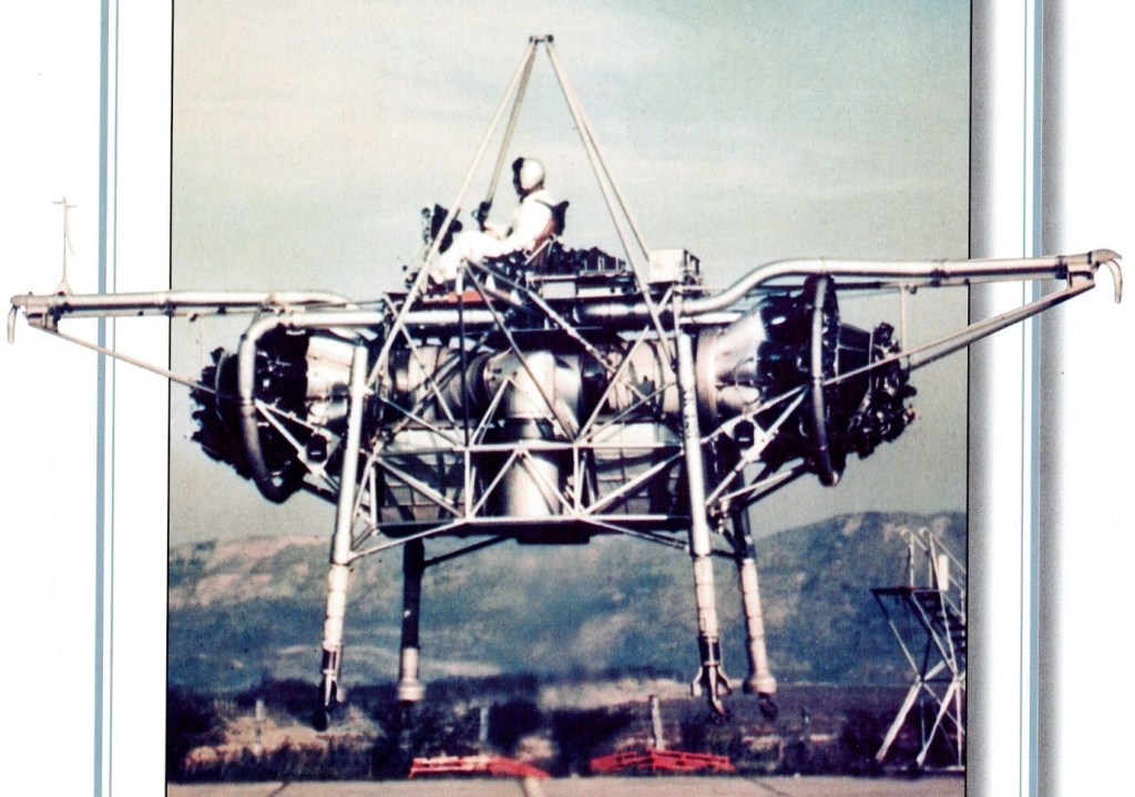
Its pilot sat on a control station atop an entirely open-air framework of tubing, a calliope of ‘puff-pipes’ for attitude control arranged all around him. It was nicknamed the ‘Flying Bedstead’. NASA were interested in its reaction control system for their lunar lander simulator.
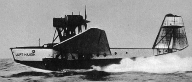
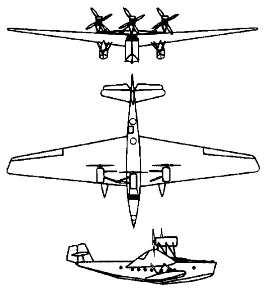
A long-range passenger flying boat, the first prototype flew on August 7, 1928.
Two models were produced. The Romar I (Werk Nrs 29,30 and 31), registrations D-1693, D-1734, and D-1747 respectively.
The single Romar II built, Werk Nr 62, went to France on the 1st April 1931 as F-AKEM.
The difference in the models was that the Romar II had BMW VIaU engines driving through a Farman gearbox.
At some point the fin was changed on all models.
The three German aircraft, named “Hamburg”, “Bremen” and “Lubeck”, were all scrapped in 1933.
Ro X Romar
Engines: 3 x BMW VIUZ, 485kW
Wingspan: 36.9 m / 121 ft 1 in
Length: 22.0 m / 72 ft 2 in
Height: 8.5 m / 28 ft 11 in
Max take-off weight: 19000 kg / 41888 lb
Empty weight: 9900 kg / 21826 lb
Max. speed: 210 km/h / 130 mph
Ceiling: 2800 m / 9200 ft
Range w/max.fuel: 4000 km / 2486 miles
Crew: 4-5
Passengers: 12