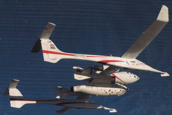
Dubbed the White Knight, this aircraft is designed to lift a rocket-powered spaceship (SpaceShipOne) to 50,000 ft for a zoom into sub-orbital space.
Dubbed the White Knight, this aircraft is designed to lift a rocket-powered spaceship (SpaceShipOne) to 50,000 ft for a zoom into sub-orbital space.
The configuration selected was a twin engine pusher-tractor tandem wing vehicle with twin booms connecting the tip of the forward wing through the center wing terminating at the vertical fin. The cabin was only large enough to accommodate the crew of two and provisions for the estimated 9 day flight.
Structural sample testing was conducted as the first step in the program to determine the lightest materials and fabrication processes available appropriate to the vehicle requirements. It was determined that .010-inch graphite tape skins, with 1/4-inch Nomex honeycomb core would provide adequate structure, and, with suitable application of film adhesive, would also be an adequate fuel barrier. The spars were made from graphite tape and Nomex cores, and were autoclave-cured by an outside vendor.
The result was an airplane with a structural weight/gross weight fraction of only 9%; significantly lower than any existing man-rated airplane. This was key to the Voyager’s success, because the amount of fuel carried, in relation to the vehicle’s takeoff weight, had the strongest influence on range.
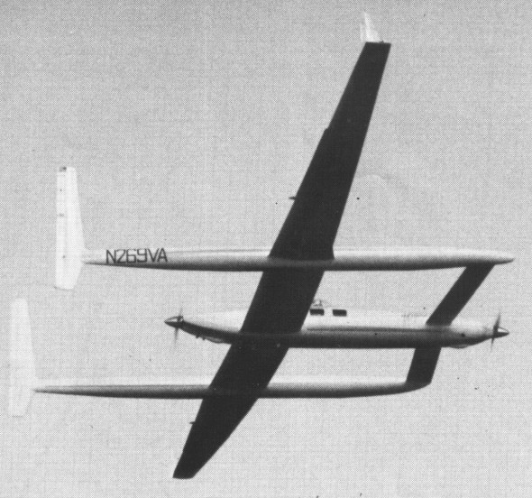
Making its first public debut, at the Oshkosh Fly-in on 29 July 1984, was Rutan’s Voyager. The previously-secret aircraft has been under development for more than three years in the Rutan Aircraft Factory in Mojave, California. The Voyager was designed by aeronautical engineer Burt Rutan, 40, for one special mission: very long range flight. “When we started the analysis, the numbers showed that it might be possible to fly completely around the world non-stop. No one has ever tried it before,” Rutan said, “so that became our goal.”
Carbon fibre and Kevlar comprise the major part of Voyager’s struc¬ture, allowing a wing span of 110.8 feet with an aspect ratio of 33.8. The spars are made from solid, oven-cured, carbon graphite, while the skins are thin carbon fibre sheets over a nomex paper honeycomb core, with no metal anywhere in the basic structure other than fasteners.
The engines are mounted in tandem, one on each end of the fuselage. It is now planned that the front engine will be shutdown and its propeller feathered after enough fuel has burned off to allow the rear engine to sustain flight. Mounted between the canard and main wing are three streamlined bodies: the fuselage (33 feet in length) and two outrigger tanks for fuel.
The structural weight of the Voyager is only 938 pounds yet the take-off weight for the global flight will be 11,236 lbs, more than six times its empty weight of 1,858 lbs. Sixteen separate fuel tanks scattered among the wings, canard, booms and fuselage, contain 1,489 United States gallons of fuel weighing 8,934 lbs, leaving just 534 lbs for the crew of two and support equipment. The final landing weight of the aircraft is expected to be only 2,300 pounds. The pilot sits within a bubble canopy above and to the right of the cabin, which contains a stretcher and an area of relative privacy for the off-duty crew member. Comfort is important, as pilots Jeana Yeager and Dick Rutan expect to spend two weeks on their 25,000 mile flight. Their intended flight path will take them across southern United States, in a curve parallel with the northern coast of Brazil, of f the tip of South Africa, across the southern Indian Ocean and north again over Australia and the Pacific and back to California. Keeping to the oceans will eliminate any political problems associated with over flying potentially hostile countries, and Australia can be relied on to be friendly.
The aircraft’s fuel capacity is 1489 gallons, carried in 17 tanks and metered by only one gauge; the crew will use one seat and one bed during the thirteen day flight, flown at between 12 and 15,000 feet on a cruise of around 110 knots; only 3.2 lbs of paint were used on the exterior; there is only one brake, on the nosewheel, and only one rudder, on the left hand fin. July 1984 the Voyager flew 11,593 miles (almost half way around the world) over a closed circuit course along the Californian coast during a test run.
Dick Rutan made history in 1986 when he and copilot Jeana Yeager made the first non-stop, non-refuelled flight around the world. Their aircraft Voyager was designed by Dick’s brother, Burt. Dick and Jeana took off with 1490 gallons of fuel on board and returned home after flying 26,680 miles non-stop with 18 gallons to spare. The flight took 9 days, 3 minutes and 44 seconds.
Rutan Voyager Around the World Article
Rutan Voyager
Length: 32.48 ft / 9.9 m
Height: 10.171 ft / 3.1 m
Wingspan: 110.892 ft / 33.8 m
Wing area: 362.747 sq.ft / 33.7 sq.m
Aspect ratio: 33.8
Max take off weight: 9695.4 lb / 4397.0 kg
Weight empty: 2683.5 lb / 1217.0 kg
Max. weight carried: 7011.9 lb / 3180.0 kg
Max. speed: 130 kts / 240 km/h
Landing speed: 70 kts / 130 km/h
Cruising speed: 86 kts / 160 km/h
Service ceiling: 16404 ft / 5000 m
Wing loading: 26.65 lb/sq.ft / 130.0 kg/sq.m
Range: 23719 nm / 43928 km
Engine: Continental IOL-200, 81 hp
Crew: 2
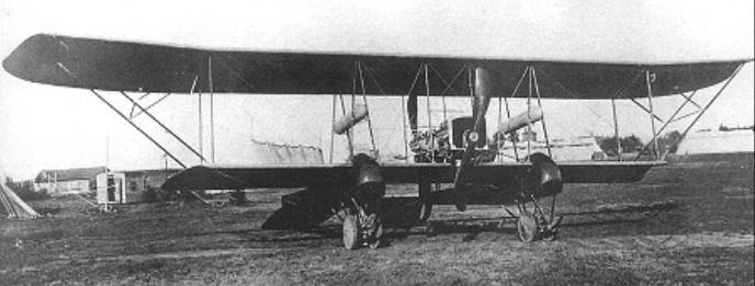
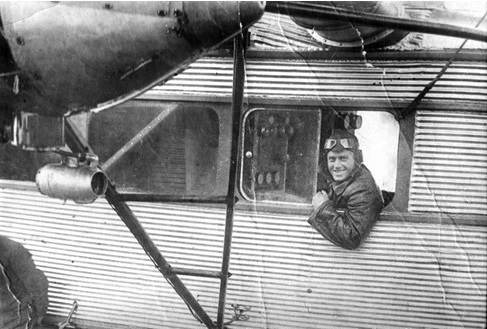
The S-19 had two 150hp Sunbeam engines in tandem and a cockpit in the nose of each of the twin tailbooms that projected slightly forward of the lower wings. The design seems to have emanated from the Russian War Department, which ordered the RBVZ to match German experiments with twin-boom combat aircraft. The prototype was completed in late 1916.
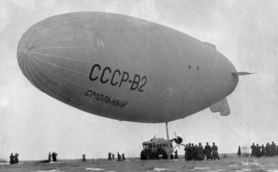
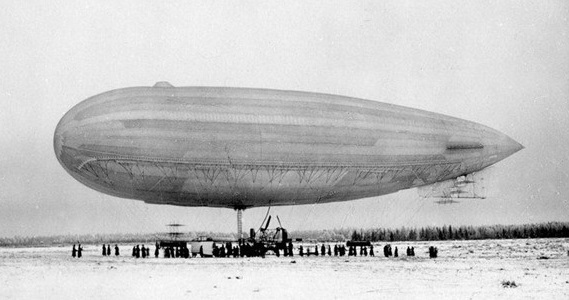
By May 1932, the Russian Empire had built three airship — the USSR B-1, B-2 USSR “Smolny” and the Soviet B-3 “Red Star”, which in the main have been set up to implement educational and propaganda operations. The B-1 envelope was 2200 cubic meters and B-2 5000 cubic meters. The airships had different engines. The V-2 had two 230 hp engines and could carry 8 passengers. The envelope of all 3 airships was made of three-layer rubberized material and had an inner wall that divided the volume of the two equal parts. This partition to reduced transfusion of gas along the envelope for trim of the craft.
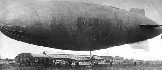
These three airships performed a series of successful flights on the routes of Leningrad — Moscow — Leningrad, Moscow — Kharkov, etc. The three airship were joined by USSR-4.
On September 6, 1935 USSR-2 Smolny was at the Stalino (Donbass) airport, when wind pulled out of the ground all 60 anchors that held it. Have seized on one of the cables commander of dirigible NS Gudovantsev managed at an altitude of 120 meters to get to the gondola, in which at that time were 4 crew members and 11 tourists. At an altitude of 800 meters the engines were running. After that, having waited for the adverse weather conditions to decrease, the airship landed safely after 5 hours and 45 minutes. For this heroic act Gudovantsev was awarded the Order of the Red Star.
The airship crashed in the Novgorod Region in 1933 when its engines failed.

The airship was disassembled in 1939.
By May 1932, the Russian Empire had built three airship — the USSR B-1, B-2 USSR “Smolny” and the Soviet B-3 “Red Star”, which in the main have been set up to implement educational and propaganda operations. The B-1 envelope was 2200 cubic meters / 78,000 cu ft and B-2 5000 cubic meters. The V-1 was designed to pick up passengers without landing. The airships had different engines. The envelope of all 3 airships was made of three-layer rubberized material and had an inner wall that divided the volume of the two equal parts. This partition to reduced transfusion of gas along the envelope for trim of the craft.
These three airships performed a series of successful flights on the routes of Leningrad — Moscow — Leningrad, Moscow — Kharkov, etc. The three airship were joined by USSR-4.
During The Second World war SSSR-V1 was used for carrying supplies for captive balloon units of Red Army, making more than 900 flights.
Engines: 2 x 75hp
Envelope: 2200 cu.m / 78,000 cu ft a
Top speed: 55 mph
Endurance 12 hr
Crew of 7
Designer by Nemchenko and built in 1912 at the plant “Duflon, Constantinovich and Co”, the semi-rigid Kobchik / Falcon airship was sent to the Far East, but not used. Builders S. Nemchenko and A.E. Garut.
Engines 2 x 50 hp
Envelope: 2150 cu.m
Length: 48 m
Diameter: 9.5 m
Max speed: 50 kph
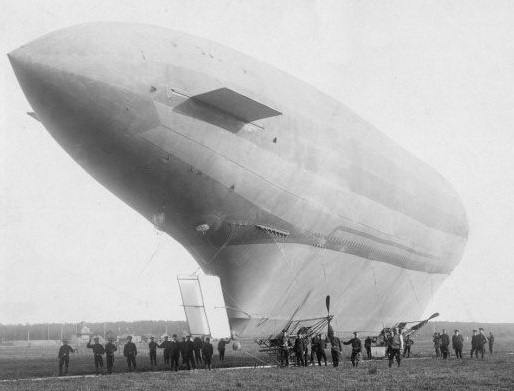
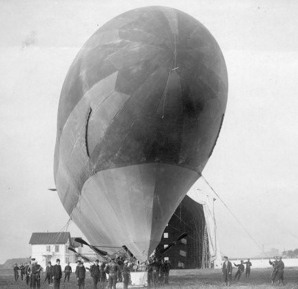
The airship “Albatross” was built on Izhorskij in 1912.
After one test flight in the hangar the “Albatross” burst. The dirigible was reassembled in Petersburg, Russia in 1913 and changed to the non-rigid “Albatross-II”.
During the First World War the Albatross II made seven bombing patrols but the missions were never completed either because of low clouds, fog, or other reasons.
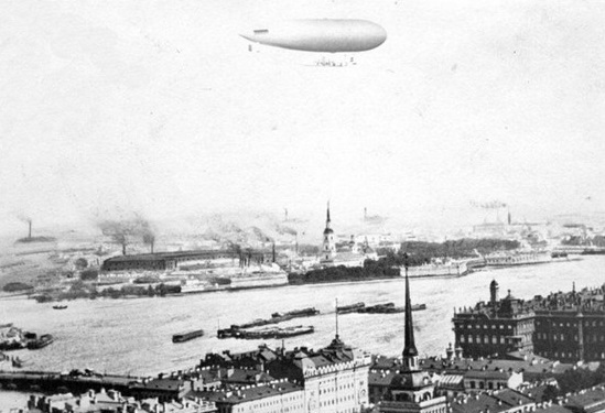
When flying on October 13, 1914, the Albatross II got into a thick fog with a strong wind, and walking at low altitude, flew into a tree and crashed. The crew were not injured.
Albatros
Envelope volume: 10000 cu.m
Endurance: 20 hr
Albatross II
Engines: 2 x 158 hp
Length: 77 m
Width: 15 m
Envelope volume: 9600 cu.m
Maximum speed: 68 km / h

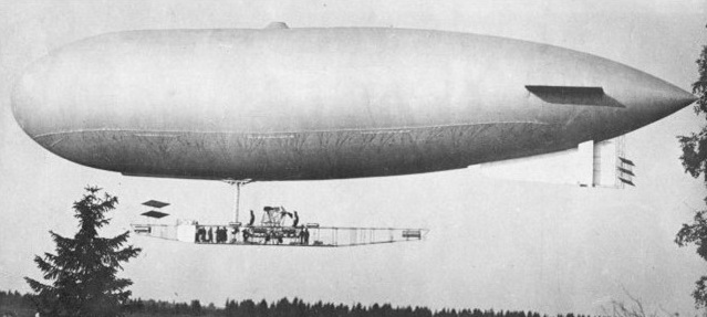
The “Aviateur”, as designed and built by Louis-Étienne Roze. Recognizable due to the catamaran configuration of the rigid airship hulls. The Aviateur was a putative challenger for the Deutsch de la Meurthe prize, eventually won by Santos-Dumont using his No. 6 dirigible – but when tested in 1901, it failed to fly.
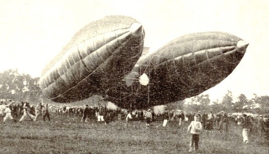
Trials took place on the 5th and 6th of September 1901. Miscalculations by M.Roze meant the airship was too heavy and managed to lift only fifteen feet, then coming down and landing softly. At 10 hp each, the two Santos-Dumont (Buchet) motors were too weak. The inherent problem with the motors was that they served the lifting propellors, which in turn had to be switched over to the propulsion/push propellors to move forward. Thus , no forward flight and the silk “wings” remained vertical, not closing to the horizontal.
As Roze had no further financial means to build the Aviateur larger nothing was ever heard of his airship again.
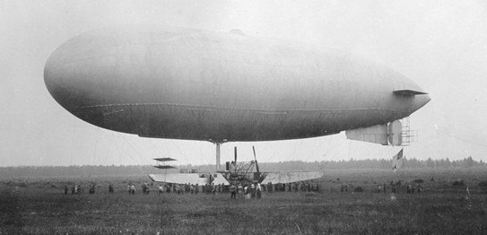
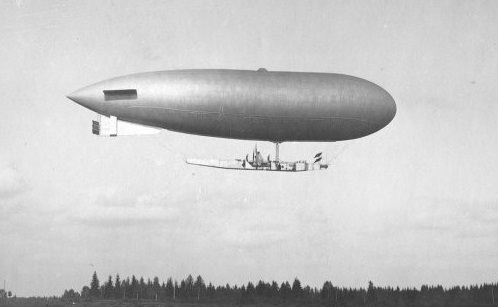
The “Eta” which in a progressive series of small experimental airships built at the Royal Aircraft Factory. The small airships that have been built there were quite inadequate from the standpoint of national requirements.
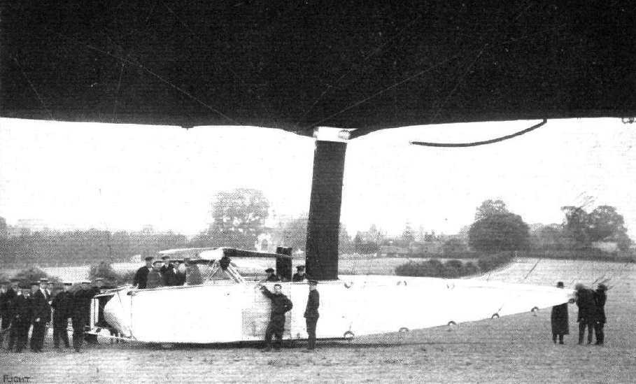
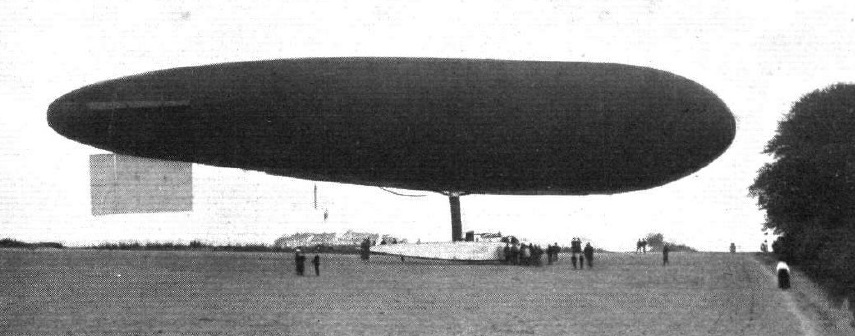
The capacity of the 1913 “Eta” is 100,000 cubic ft, and.it carried 160 hp in two radial stationary Canton-Unne engines, set on opposite sides of the car with their axes placed transversely. Oblique shafts transmit the power to gearing, supported by an overhead framework, which also carries the swivelling propellers. As the airship ascends, these propellers are swivelled round, so that ultimately their axes are horizontal for full speed ahead. In order to stop the airship they can be turned completely round so as to thrust backwards, and they can similarly be used for lowering the airship for the purposes of descent.
Launched in August 1913, the Eta was a non-rigid of 118,000 cu.ft incorporating twin ballonets and capable of 46 mph. The Eta introduced the ‘Eta patch’ in its design as an improved anchorage system for car suspension that greatly reduced drag. The Eta patch allowed the car to be made smaller and attached nearer to the envelope, providing a better streamlined form and reducing drag. The patch consisted of a steel ring through which several layer of overlapping material were rove, forming a fan-shaped patch with the ring positioned at the lower apex. The overlapping layers of fabric were glued and stitched to each other and to the envelope, forming a strong attachment position allowing fr better distribution of load.
On August 19, 1913, “Naval Airship No.2” (the re-constructed “Willows No.4” – under the command of Lieut. Neville Usborne, R.N.) experienced engine failure due to a broken crankshaft near Odiham in Hampshire. In order to save the hydrogen in the disabled airship, it was decided to try and tow it home employing the airship “Eta” – newly-constructed by the Royal Aircraft Factory and currently undergoing its acceptance trials. Accordingly, a tow-line was attached and the two airships ascended, the “Eta” keeping about 600 feet above the towed ship so as to avoid all chances of fouling the rudder gear. The approximate 8-mile trip back to the airfield at Farnborough was made at a groundspeed of 25 mph against a 5 mph headwind. The “Eta” was in all probability skippered by Army Capt. Waterlow at the time.
1917 Bomber. Development of F.E.4: project only.
Engine: 2 x 250-h.p. R.-R
Span: 67ft 10.75in
Seats: 2
