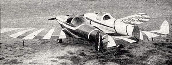
This aircraft was converted specifically for airshow work. The “Twin ‘Coupe” was built by Grady Thrasher for use in the “Thrasher Brother’s Air Show” in 1946. The elevator restrictions were removed. It was used until Grady retired from airshow flying for the US Army in 1950.
Seen performing as part of “The American Flag Parachute Jump.”
The Twin Ercoupe was sold to a dealer in Ercoupe dealer in Columbus, Georgia who scavenged it for parts.
A search of the FAA registration database says that NX93384 was a 1946 Ercoupe 415-C, s/n 707. The last registered owner was Elbert Elms of Collinsville, IL.
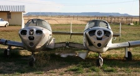
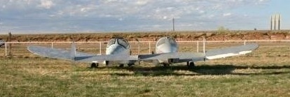
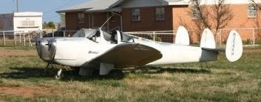
Discovered in 2007, another Twin Ercoupe, marked as N87078, was spotted off I-40, in Tucumcari, NM.
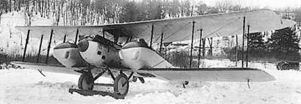
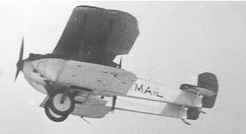
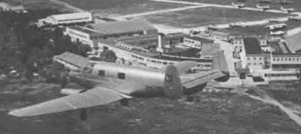
The Thomas-Morse MB-4 mail carrier of 1920 had a centerline tractor/pusher engine nacelle pod in the middle, and twin fuselages from surplus MB-3s on either side. The bad characteristics included one fuselage tended to take off before the other, no communication between cockpits, and excessive motor vibration.
One went to the USPO but was never used in service and scrapped in 1921. Three went to the US Army (AS64306, AS64373 and AS64374); the first one to McCook Field as P-172.
Engine: 2 x Wright-Hisso H, 300hp Wingspan: 45’6″ Length: 25’5″ Useful load: 2010 lb Max speed: 140 mph Cruise: 122 mph Single-engine cruise: 100 mph Range: 600 mi Seats: 2
In 1916 construction was underway on the Thomas Bros BP three-place open cockpit twin engined biplane. It was a folding-wing “battleplane” project but cancelled after the Army expressed no interest.
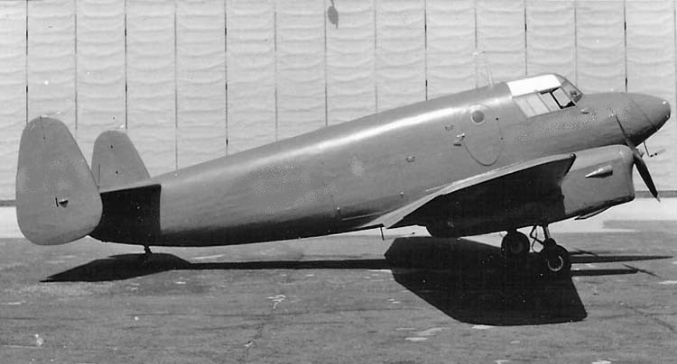
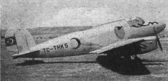
The THK-5 was a twin-engine aircraft developed in Turkey as an air ambulance. First flying in 1945, it was a conventional, low-wing cantilever monoplane of wooden construction throughout. The main units of the tailwheel undercarriage retracted into the wing-mounted engine nacelles and the THK-5 could carry two stretcher cases plus a medical attendant.
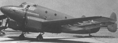
THK-5A TYRKEN (c/n 503 / OY-ACK) light ambulance a/c of the Danish FALCKS REDNINGSKORPS
This was followed in production by a six-seat utility transport version designated THK-5A and three examples of an improved version of the 5A designated THK-10. A single example of the type was exported, sold to Denmark.
On September 6, 1951 THK-5A serial number 503 sold to Denmark was put into service with registration OY-ACK. The aircraft, which was used as air ambulance under the name TYRKEN (TURK) until logging 961 hours and 20 minutes. In 1960 it was resold and used by air taxi companies. On 18 November 1961 the airplane suffered a landing accident and was withdrawn to a children’s park in Lagunen. The wreck was eventually scrapped.
THK-10
In total 13 were built.
When THK was taken over by MKEK, this was one of the designs selected for further work. However, although the designation MKEK-5 was allocated, nothing further came of this.
THK-5 Engine: 2 × de Havilland Gipsy Major, 123 kW (165 hp) each Wingspan: 14.63 m (48 ft 0 in) Length: 9.98 m (32 ft 9 in) Height: 2.87 m (9 ft 5 in) Empty weight: 883 kg (1,943 lb) Gross weight: 1,920 kg (4,255 lb) Maximum speed: 220 km/h (137 mph) Cruise speed: 124 mph Landing speed: 74.5 mph Range: 646 km (404 miles) Service ceiling: 4,000 m (13,100 ft) Crew: Two pilots Capacity: Two stretcher cases plus one medical attendant
The Texas Aircraft Factory Me 262 has its origins as an original 262 found in a dilapidated state at Willow Grove Naval Air Station, Pennsylvania. The aircraft, one of 11 examples taken to the United States in 1945 and, while none flew again, they did assist America with its jet aircraft development programme. There were no blueprints for the sheet metal and wood 262 and the aircraft was gradually disassembled and all parts duplicated with enough to make five new aircraft. Its original Junkers engines were unreliable and needed overhauling every ten hours, and accordingly the new jet has two General Electric J 85 engines, giving twice the power and half the weight of the originals.
The Me 262 was a stunning design triumph, and the influence of the plane can still be seen in contemporary combat aircraft. Swept wings, automatic slats, modular construction … all were leading advances for the time. More than any other aircraft of its day, the 262 was a fighter of absolutely unrivalled potential.
Still, despite this fortuitous blend of brilliance and chance, the Me 262 suffered from some well-known, and potentially catastrophic, weaknesses. The engines, landing gear and brakes were all decidedly failure-prone, and these systems often caused the losses that the Allies could not.
One of the most overlooked aspects of the Me 262 Project lies in the extraordinary engineering and design work that has gone into integrating authenticity with safety. In our desire to create a worthy duplication of the original aircraft, we have developed a number of ultra-low profile improvements which will greatly enhance operator and flight safety. In the case of the J-85 replacing the Jumo 004, this is a rather overt matter; however, several other critical improvements have been quietly incorporated into the design to insure that these jets do not suffer the same fates as so many of their predecessors.
The precision engine castings were first proposed, then designed, by the late Steve Snyder. As an aeronautical engineer, Snyder recognized that simply hanging a pair of J-85s on the Me 262 within oversized cowlings would create as many problems as it solved. Differences in wing root forces, weight distribution, and the Center of Gravity would have completely altered the characteristics of the original Me 262. His solution may have been borne of necessity, but it has emerged as one of the most innovative engineering feats in the entire effort.
Detailed castings have been made from an original Jumo engine, and all related accessory drive components, gearboxes and pressure lines will be precisely duplicated for surface-mounting. When the access panels are opened, bystanders will see a historically accurate duplicate of a Jumo 004B engine. Concealed deep within the casting, the modern powerplant will go all but completely unnoticed.
Perhaps most significantly, the entire assembly (when mated with the J-85) will closely duplicate the nacelle weight of the original Jumo 004. In this respect, the original performance characteristics of the aircraft will be faithfully preserved.
As the landing gear was known to be another weak area on the original Me 262, a detailed analysis of landing gear stresses was directed. This process revealed that a shock loading was generated by the spin-up forces of the large, heavy main wheels, which had to be reacted into by the wing landing gear attachment structure. This placed a severe demand upon wing spar area and the airframe simply had to absorb these forces. Over time, this would have had a devastating effect upon the aircraft.
In part, this problem can be traced to the history of the aircraft. As originally designed, the Me 262 was equipped with a standard tail wheel (in lieu of the nose wheel).
In the tail-dragger configuration, the main gear was bolted directly onto the wing spar; however, the tricycle modification resulted in the creation of a separate wing torque box to be used as a mounting point. This torque box was susceptible to damage, and very difficult to repair.
On the new Me 262s, this area has been reinforced with additional structural features, and the project is considering additional design changes that may further enhance the safety and longevity of the landing gear. In addition to the wing box reinforcement, the nose gear mounting point and strut assemblies have been greatly improved. In short, the entire system has been strengthened by a significant margin above what it was originally.
The braking systems of wartime German aircraft usually left something to be desired, and the Me 262 was no exception. Brake fading and/or complete system failures were a common complaint.
The notoriously ineffective nose wheel brake has been eliminated altogether, although the original brake lines will be duplicated for appearance. Meanwhile, the marginally performing drum brakes on the main gear have been replaced by a cleverly-integrated disc brake system. The improved disc brakes have been mounted within the wheel hub assembly itself, and have the capacity to stop an aircraft more than twice the weight of the Me 262.
Despite the fact that the nacelle weight will be roughly equal to that of the original Me 262, the power available to the pilot has still been significantly improved. Since the characteristics of the airplane were well known at the 1,800 pound thrust level, every effort has been made to duplicate this performance envelope, and not create some “Super Me 262” class airplane. Still, the fact remains that the increase in thrust is significant enough to consider some entirely new engineering aspects.
While a positive development in most respects, the added power can present new problems of its own. For example, an engine failure during a full power takeoff could quickly result in an uncontrollable asymmetric thrust component. The project engineers understood this problem, and developed a simple method to control the situation. To address these issues and provide the pilot an accurate indication of actual power settings, the project has carefully modified the throttle assembly to be fitted with a throttle pressure spring which provides a positive force indication of engine RPM at 1,800 lbs. thrust. In other words, the pilot will know when the maximum specification thrust levels of the Jumo 004 have been reached.
If the pilot desires additional power, he may push the throttles beyond the spring loaded position, holding them open against this spring pressure. The actual hard stop for the throttles will be set at the J-85’s maximum thrust setting, which is projected to be around 2,400 to 2,500 lbs., as mounted. The additional power is reserved for two operational regimes. On takeoff roll, prior to liftoff, and during climb. Takeoff roll is initiated with full power, but it is then reduced to the original Jumo takeoff thrust level (1,800 lbs.) just prior to liftoff. The excess power may be added once safe climb speeds of 260 Miles Per Hour are achieved.
The Junkers Jumo 004 is often remembered as a temperamental and failure-prone powerplant. Despite its advanced design, engine life was only between 10 and 25 hours, with the mean being at the lower end of this range. These failures were anticipated to some extent and the Me 262 was designed to permit extremely rapid engine changes. Contrary to popular belief, the 004A was a fairly sound performer when premium steels were used, and early versions were known to achieve a 200-250 hour service life. However, the diversion of critical materials into U-boat production and other projects late in the war forced Junkers to produce the 004B model with only 1/3 of the high grade steel that had been used in the 004A. It was to be a disastrous concession for the Me 262.
The introduction of inferior metals compounded an already problematic situation with the turbine blade design. These blades were rigidly mounted, contributing to severe root stress relief problems. The weaker metals simply could not withstand this kind of abuse and regular compressor failures were an inevitable consequence.
The General Electric J-85/CJ-610 series turbojet engine was originally designed in the 1960s for use in military applications. Shortly thereafter, civil certification and production followed under the CJ-610 designation. The CJ-610 was quickly selected to power the popular Gates Learjet; meanwhile, its military cousin was called into service with such noteworthy combat aircraft as the F-5 Freedom Fighter and A-37 Dragonfly. The resilience and forgiving qualities of the engine also made it a natural choice for training aircraft, and the J-85 was adopted for both the T-38 Talon and T-2J Buckeye.
The J-85/CJ-610 engine has a reputation for extreme reliability, allowing wide variations of inflow distortion. It also places a minimal maintenance burden upon ground crews. Proven in war and in peace over three decades, the engine is ideally suited to power this classic warbird well into the next century.
In aircraft applications, engine power is characteristically measured in terms of thrust versus weight. The Jumo 004 was typical of early jet engines in that it was rather heavy, and not especially efficient. Production model 004s produced 1,980 lbs. of thrust, and weighed in at about 1,800 lbs. Because of this, the engines were not extraordinarily effective at low airspeeds or altitudes or at reduced power settings. Long takeoff rolls (>3,000′) were evidence of this phenomenon and, once aloft, power management became critical. Abrupt throttle changes or rapid maneuvering often resulted in a flameout, or worse, a complete compressor failure. Each J-85 produces 2,850 lbs. of thrust, yet weighs only 395 lbs. In simpler terms, the new engines offer nearly twice the power for less a quarter of the Jumo’s weight penalty. The design dynamics of the Jumo engine castings are expected to reduce the thrust available by about 300 lbs. per engine. Engineering estimates call for an actual power output in the vicinity of 2400-2500 lbs. per engine. Integration of the J-85 will bring many noticeable improvements. Takeoff distances will be significantly shortened (<2,000′), and time-to-climb rates vastly improved. Also, the J-85 responds well to varying power demands (including low power settings) and is highly tolerant of the kind of airflow disruptions that gave the Jumo such difficulty.
The Jumo-powered Me 262 was capable of level flight speeds in excess of 540 miles per hour at altitude; a trait that made it all but invulnerable to Allied escort fighters. Higher airspeeds were recorded under certain circumstances but, in general, compressibility-related aerodynamic factors prevented the airframe from ever pushing into the high transonic range. Postwar tests in the West confirmed that at very high airspeeds airframe vibration levels and buffeting grow increasingly worse until the jet enters into a shallow dive and becomes all but completely uncontrollable. Recently revealed Soviet documents demonstrate that this was also a major finding in Red Air Force flight testing of the Me 262.
In purely theoretical terms, the added power of the J-85 should give the new production Me 262s a speed advantage of at least 75 miles per hour over any previous generation Me 262. In the interest of safety, the Me 262 Project will be placing a placarded airspeed limitation upon the jets in the vicinity of 500 MPH.
Specific Fuel Consumption (SFC) values provide a quantifiable and uniform means of measuring a turbojet engine’s efficiency. All jets have an associated SFC, and for the Jumo 004, the correct figure is 1.39. In practical terms, this means that for each pound of thrust provided, the Jumo will burn 1.39 pounds of fuel per pound of thrust per hour. With a typical fuel capacity of 1,800 liters, the range of the original Me 262 was approximately 600-650 miles (at altitude). The J-85 has a Specific Fuel Consumption value of .99, meaning that it will burn slightly less than one pound of fuel per pound of thrust per hour. When compared to the Jumo, the J-85 is obviously some 40% more efficient.
This improvement will have a marked impact upon both the range and endurance of the of the new Me 262s. A new Me 262 should be able to travel well over 1,000 miles on a single fuel load.
The first effort to make Me 262 copies, which began in the early 1990s and involved warbird fan Stephen L. Snyder and a Texas aircraft restoration company, Classic Fighter Industries, dissolved in acrimony. Snyder called on Bob Hammer to take over the work. The effort was barely under way when Snyder died in the crash of his North American F-86 jet fighter in 1999.
Bob Hammer recalls the day ten 18-wheel tractor trailers dumped the pieces of five Messerschmitt Me 262 Stormbird jet fighter reproductions in a hangar near the city of Everett, Washington. The pieces had been trucked in from Texas, where an initial attempt to build the aircraft had ended in lawsuits. “Parts everywhere—parts, parts, parts,” says Hammer, a retired Boeing engineer. “You never saw such a mess.”
That was in December 1998. For Hammer and a small team of volunteers, it was just the start of a long process to put the Me 262 back in the air. Now, the Me 262 Project, as it is called, has logged numerous successful flights and delivered two of the German aircraft, with a third nearing completion. With their project, Hammer and his team have brought the world’s first production jet fighter back to life.
“At times we thought this was stupid and should just give up,” says Jim Byron, another retired Boeing executive who pitched in. “But that’s not the Boeing mentality, so we kept plugging along.”
Hammer and Byron—along with dozens of volunteers— worked doggedly on the difficult aircraft. Hammer is something of an aviation prodigy, a youthful-looking, sandy-haired 67-year-old who favors faded blue jeans and T-shirts. He spent 38 years at Boeing, working as chief engineer on the 757, among other projects. He has also built an array of aircraft in his spare time, most recently a four-seat Seafire amphibian that was named Grand Champion Seaplane at the 1998 Experimental Aircraft Association airshow in Oshkosh, Wisconsin. On the Me 262, he handles most of the engineering challenges, while Byron, an avuncular 68-year-old with white hair, runs the office and manages the volunteer team.
The Me 262 Project is headquartered in a non-descript hangar at Paine Field, a large airfield north of Seattle. Aviation maintenance giant Goodrich has a facility there, and Boeing uses the field to roll out new 747s and 777s for their first flights after they leave the nearby wide-body plant. On the second floor of the hangar is a warren of offices and meeting rooms, the walls covered with Me 262 photographs and drawings. Downstairs, a crowded shop holds a completed Me 262 and more in assembly—wings, engines, and shelves of parts scattered around.
Hammer and his team took over the Me 262 project in late 1998, and their first task was to finish Vera, a derelict Me 262 that Steve Snyder had found sitting outside the Willow Grove Naval Air Station near Philadelphia. Vera had been captured after World War II and flown as an experimental aircraft until it was sent to Willow Grove, where it sat on static display for many years. In exchange for the right to use Vera (the nickname came from the sister-in-law of a pilot who had helped capture Me 262s after World War II) as a template, Snyder had agreed to restore the aircraft to static-display quality. Snyder’s death nearly ended the Me 262 Project. But Hammer talked with two buyers he had lined up for Me 262 reproductions—the Messerschmitt Foundation in Munich, Germany, and a retired judge in Arizona named Louis Werner—and they agreed to finance both the restoration of Vera and the construction of two reproductions of the old warplane.
The goal of the Me 262 Project was not to make an identical copy of the original aircraft; some concessions have been inevitable. The original Junkers Jumo jet engines, for instance, were famously prone to breakdowns and often good for no more than 10 hours of flight (although some built with higher quality steel reached a service life of 200 hours or more). So the engines used by the Me 262 Project are the reliable, proven GE J85 engines found on many business jets. The Me 262’s nose gear was notoriously fragile, with the Germans losing many aircraft to nose wheel collapses. Hammer fashioned a brace for the gear that eliminated the problem. And all the aircraft have modern radios and navigation gear.
Overall, though, the team has stuck as closely as possible to the real thing. While aluminum would have been lighter, the skin was made of steel, like the skin on the originals—a concession to wartime aluminum shortages. The instrument panel was made from plywood, as were the landing gear doors. The use of Phillips-head screws seemed like a reasonable substitute, but guests from the Messerschmitt Foundation, who planned to make a flying copy of the Me 262 the centerpiece of their collection of Willi Messerschmitt-designed airplanes, insisted that slotted screws, identical to those in the original, be used. “We only need 500, but had to buy 15,000 of them,” Byron chuckles, comparing his request for slotted screws to walking into a modern RadioShack and asking to buy television tubes. “They said ‘We’ll do it,’ but once they set up to make slotted-head screws, they had to crank them out like yards of sausage.”
Hammer’s group needed nearly four years to transform its pile of parts into a flying Me 262. Problems abounded. At one point, for instance, the team was confounded by the controllers for the engine generators, which provide electricity to the aircraft. “It was the worst kind of problem—an intermittent one,” says Hammer. The controllers would occasionally burn out a relay for no apparent reason, shutting down power to the aircraft. “It was driving me nuts.” Finally, Hammer found a retired electronics engineer who agreed to pore over the controllers’ complex wiring schematics (“They looked like a road map from here to Greece,” says Hammer). After two days, the engineer unearthed a fault in the original Air Force wiring diagram, which caused the project team to miswire the controllers.
The team also faced headaches in getting the brakes to work properly (modern disc brakes replace the failure-prone drum brakes on the original), and in balancing the 2,500 pounds of thrust from the GE J-85 with the flying characteristics of the Me 262, which was designed for a less-powerful engine. “People think that once you have an airframe, you’re 90 percent of the way there,” says Hammer. “Hell no. That’s only about 15 percent…. The rest is integrating all the rest of this stuff so it works together.”
Hammer came to greatly admire the Stormbird. The name (Sturmvogel in German) refers to the fighter-bomber version of the aircraft, but seems more fitting than the fighter’s name, Schwalbe, which means Swallow. “I was really impressed with the way the airplane was designed for easy assembly,” he says. “They were building this thing in woods and caves and everywhere else, so parts were built all over the place and then put together.” The cockpit “tub,” for instance, was a single assembly that could be dropped into a fuselage. Wing and control components were similarly designed for easy construction and assembly.
The project has three distinct aircraft variants. Each of these airframes carries an original factory designation which corresponds to the basic design (A-1c or B-1c as appropriate). The “c” suffix refers to the new J-85 powerplant and has been informally assigned with the approval of the Messerschmitt Foundation in Germany. During the war, all operational Me 262s were “a” models, which signified installation of the Jumo 004 engine. Experimental “b” models used the BMW 003 powerplant, leaving “c” as the next unassigned letter.
Configurations: 1. Me 262 A-1c Single-seat fighter variant 1 airframe
Me 262 B-1c Two-seat trainer variant 2 airframes
3. Me 262 A/B-1c Conversion (single or two-seat) variant 2 airframes
Each was assigned a unique Werknummer (W.Nr.) and registry. The first to take flight was Me 262B-1c W.Nr. 501241 (N262AZ), which became airworthy on December 20, 2002, and in 2025 was operated by the Collings Foundation in Houston, Texas. Another, the Military Aviation Museum in Virginia Beach, Virginia, maintains Me 262A/B-1c W.Nr. 501243 (N262MF) in flying condition. Meanwhile, Me 262A/B-1c W.Nr. 501244 (D-IMTT) is based in Germany under the care of the Messerschmitt Stiftung in Manching, where it also remains airworthy. Me 262B-1c W.Nr. 501242, is on static display at the Evergreen Aviation Museum in McMinnville, Oregon, painted in the markings of Jagdgeschwader 7 (11./JG 7), as flown by Leutnant Alfred Ambs.
Finally, on December 20, 2002, aviation history was made…again. Wolfgang Czaia, a former pilot for the modern German Luftwaffe (Czaia still flies Lockheed F-104 Starfighters as part of the Starfighters Airshow Demonstration Team) and a retired 757/767 captain for American Airlines, flew an Me 262 dubbed White One at Paine Field. For 35 minutes, Czaia made gentle turns and tested the airplane’s stall characteristics while keeping the gear down. “A pleasure to fly,” Czaia wrote in his flight test report. “Overall, a great first flight.”
On the next flight, January 18, the gear was retracted. Right away Czaia had problems, with two red lights on his instrument panel. An observer in a chase airplane reported the gear up and doors closed. Czaia cycled the gear again. This time the nose wheel dropped only part way while the main gear stayed up. Finally, he activated an emergency system that used compressed nitrogen to blow the gear down. Success—or so Czaia thought.
As Czaia touched down, the main landing gear on the aircraft’s left side collapsed. Within seconds, the speeding Me 262 had careered off the runway and over an embankment. “That was a pretty rough ride,” recalls Czaia. “CNN had a camera in the cockpit that day and caught the whole thing.”
The horrified ground crew dashed to the crash site and found Czaia clambering out of the jet, unhurt. The airplane wasn’t so lucky. In addition to the collapsed gear, one wing was crunched and the engine nacelles had substantial dents.
The team eventually traced the problem to a landing gear actuator assembly that had been machined slightly out of tolerance in Texas. The gear had performed flawlessly during hundreds of ground tests, but the stress of an actual landing caused it to buckle. Within a week, Hammer had tracked down an original landing gear actuator and started work on duplicating it.
By the summer of 2004, White One was flying again—this time without any problems. The second Me 262, Tango-Tango, was completed in the summer of 2005, and last fall was disassembled and flown to Munich, Germany, in a 747 freighter, where it was the hit of the Berlin Airshow. Tango-Tango also flew for a Family Day at the Messerschmitt Foundation. Organizers expected 3,000 people; 90,000 showed up. A third aircraft should be flying this fall, with the last two scheduled for completion when the Me 262 Project finds buyers. After that, no additional Me 262s will be built. During the breakup between Steve Snyder and the Texas company that first worked on the aircraft, several key jigs for making wings and fuselages were lost, so the Everett group lacks the tools needed to build one from scratch. Instead, they’re tackling the restoration of a piston-powered fighter, a Messerschmitt Bf 109F that had crashed in Russia during World War II.
Meanwhile, the Me 262 Project still had three Me 262s for sale at about $2 million each. “It took far longer and cost far more money than I ever would have imagined, but we got here,” says Hammer.
Production
Werk Number: 501241 Type or Configuration: Me 262 B-1c (two seater) TAF Name: Blue Nose Me 262 Project Name: “White 1” N262AZ
Werk Number: 501244 Type or Configuration: Me 262 A/B-1c This model has been designed to be readily re-configurable between single-place and two-place models without sacrificing airframe authenticity or structural integrity. TAF Name: Red Nose Me 262 Project Name: Red 13 Tango-Tango N262MS U.S Registration deregistered 01/18/2006 D-IMTT
Werk Number: Type or Configuration: Me 262 A-1c (single seater) TAF Name: Green Nose Me 262 Project Name: White 3
Werk Number: Type or Configuration: Me 262 B-1c (two seater) TAF Name: White Nose Me 262 Project Name:
Werk Number: 501243 Type or Configuration: Me 262 A/B-1c This model has been designed to be readily re-configurable between single-place and two-place models without sacrificing airframe authenticity or structural integrity. TAF Name: Yellow Nose Me 262 Project Name: White 8
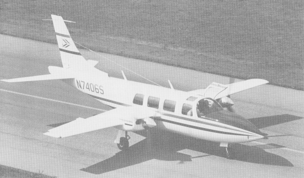
Ted Smith sold his interest in Aero Commander to Rockwell and by 1966 had completed the first mockup of the Aerostar and production commenced, with finance from American Cement, at Van Nuys. Ted Smith then sold out to the American Cement Company, which, Smith says, simply didn’t know how to run an aircraft business and consequently ran Aerostar into the ground before finally selling out to Butler Aviation, another firm with no experience in manufacture. Butler did nothing with the Aerostar, and eventually, Smith was able to buy back the company and a large inventory of parts at a much lower price than that at which he had sold out in the first place. This sequence of events is crucial; it amounted to a huge gift to Smith, who found himself able to sell a comparatively exotic airplane of excellent performance at unnaturally low prices, because he obtained his parts – enough of them to make hundreds of airplanes in some cases at a huge discount. Thus, after only a short time in business, Smith could boast of a 10 percent annual return (before taxes), one of the highest in the industry.
Designed by Ted Smith during late 1964 as a dual controlled high performance twin engined executive / light transport aircraft, the prototype N540TS first flew in November 1966 and had 160 horsepower Lycoming IO-320 engines, but the airframe was designed to take various powerplants up to turbines without major changes. Accommodating six passengers, the cabin measures 12 ft 6 in long, 46 in wide, and 48 in high and a 30 cu.ft baggage compartment aft has an external access through a 24in high and 22in wide door.
Entry through the left hand clamshell door allows everyone to board before the pilot, get settled in, and then he just slides in and buttons up. Also situated on the port side is the door to the 30 cu ft 240 lbs baggage locker. The two 24 volt batteries are situated in the rear fuselage area along with the 35,000 BTU heater. Large fowIer flaps are fitted and, like the undercarriage, are hydraulically operated. The main undercarriage wheels retract inwards while the nose wheel retracts forwards. The undercarriage is held in the up position by hydraulic pressure alone, there is no lock.
Aerostar 600
The Aerostar 600 received FAA certification (TC A17WE) during March 1968 for the Ted Smith Aircraft Co. The production type flying for the first time during October 1967. The 290 hp Lycoming IO 540, used on the first production airplane delivered in 1968, was available on Aerostars in a normally aspirated or a turbocharged version. The FAA approved the type on 12 April 1978 for Piper.
Aerostar 600A
The prototype first flew in 1966 and had 180 horsepower engines, but the airframe was designed to take various powerplants up to turbines without major changes. The 290hp Lycoming IO 540, used on the first production airplane delivered in 1968, was available on Aerostars in a normally aspirated or a turbocharged version.
The three Piper Aerostars the non turbocharged 600, turbocharged 601 B and pressurized 601P are virtually identical in appearance. Heavy, butt joined and flush riveted skins give the airplane an extremely smooth surface, and the thicker than usual gauge metal serves two purposes. Its extra strength reduces the amount of internal structure needed, and it deforms less during flight to more accurately retain its aerodynamic shape.
Aerostars all have power steering. The nosewheel is turned by pressing the left or right side of a spring loaded rocker switch on the center console. The switch actuates a solenoid that directs hy¬draulic system pressure to a combination shimmy damp¬er/steering cylinder on the nosewheel. The controls are connected by push pull rods. The right engine on the Aerostar has the only hydraulic pump, which supplies pressure for the gear, flaps and power steering. To retract the gear after a right engine failure, the propeller must be allowed to windmill for eight seconds to provide sufficient hydraulic pressure. An extended gear subtracts 300 fpm from the rate of climb. A single engine go around with the right engine dead would be extremely difficult. The optional electric hydraulic backup pump would seem a desirable investment.
There are no up-locks on the gear. It is held in the retracted position by hydraulic pressure and by a pressure accumulator should the pump fail.
Smith designed the fuel system to be as simple as possible. There is a 42 USgallon fuselage tank behind the cabin and a wet wing cell on each side extending from the engine nacelle to the wingtip. Because of the thin, laminar flow wing, these tanks are long and shallow. They each hold 66.25 USgallons usable, for a total usable capacity of 174.5 USG. The fuel gauge displays the total capacity of the three tanks; by moving a spring loaded toggle switch, you can read the capacity of either wing tank. To obtain the quantity of the center tank, you must subtract the amount in each wing tank from the total readout.
The electrically operated fuel valves (one for each engine) have three positions – on, off and crossfeed. With the selectors “on,” each engine draws from both the center tank and its own wing tank. The system is arranged so that the wing tanks will run out first, leaving the center tank to feed the remaining fuel to both engines. The intent was that for normal operations the pilot would select ‘on,’ and forget about fuel management.
The Aerostar has standard leather upholstery covering bucket seats. Most used 600s and 601s have a brake mod which apparently remedied a pad deficiency in the original system. The fuselage: four longerons, widely spaced frames, heavy skins, butt joints, all rivets machine-countersunk and shaved, wide open spaces of unsupported panel. In a departure from classical design practice, Smith designed his structures with skins one or two gauges thicker than are commonly used, and with fewer than the usual number of frames and longerons. Stringers—stiffeners riveted across wide sheet panels to prevent buckling—are omitted entirely. Smith’s rationale was that some of the added skin weight would be made up by eliminating many detail parts; and that thick skins could be depended on to provide strength in compression, while thin ones could not. Thick skins would make the wing stiff enough to be free of flutter at jet speeds, despite a laminar airfoil thin enough to have a fairly high critical mach number. The tail feathers are interchangeable. All the control surfaces are moved by push-pull tubes; there is no aileron trim— fuel is crossfed to correct wing heaviness—and yaw and pitch trim are electric, with gearhead motors providing part of the control surface balance. Mammoth fittings and pins in quadruple shear connect the wing box to the fuselage at four points. The wing box passes through the fuselage just behind the last pair of seats; above it is a large hat shelf, and behind it a fuel tank. Still farther aft in the fuselage is the luggage compartment, situated at shoulder level. The entire cabin is ahead of the wing spar. The wing loading is high—32.4 lb/sq ft at gross in the normally aspirated Model 600, whose gross weight is 5500 pounds. The fuel system is controlled by motor-driven electric valves which take their cues from three-position rotary switches on the panel: Off, On, Crossfeed. Normally, each engine feeds from,its wing and the fuselage tank; on crossfeed, it would feed from the opposite wing tank only. Fuel is taken in through three fillers, one in the fuselage and two at the wing tips (the entire wing outboard of the engine nacelles is wet), and all three sumps are drained at a convenient point on the underside of the tail cone. All hydraulic pressure, in the standard version of the system, is provided by a pump on the right engine. A small accumulator in the tail cone provides standby power in emergencies. Hydraulic power is used for the gear, flaps, and nosewheel steering. The nosewheel steering system consists of a rocker switch on a center subpanel (which also has the trim switches) which directs a restricted flow of hydraulic fluid to either side of the shimmy dampener, depending which way you want to turn. Holding the rocker switch down feeds fluid to the appropriate side, turning the nosewheel in proportion to the time the switch is held de¬pressed. Since it is the nature of a shimmy dampener to permit controlled leakage from one side of the piston to the other, the nosewheel tends to center itself gradually once deflected. A steering failure is there¬fore not critical; the airplane can be steered with brakes.
The 601A became the B model in 1977 with the addition of 15 inches to each wingtip for increased stability at high altitudes, automatic rather than manual wastegate controls and a 300 pound gross weight increase. The 1978 model has an improved wastegate that is more durable and efficient, resulting in an increase of critical altitude from 16,000 to 23,000 feet.
The first 601P rolled off the production line in May 1974, as a 1975 model. The first 601P had “short” wings, with a span of just over 34 feet. The factory extended the wings early in the production run and virtually all of the airplanes built with less span were redone by the factory to the new 36.67 foot wingspan. Maximum cruise on the first 601P was shown in the pilot’s operating hand book as 256 knots at 25,000 feet.
By 1970 the plant was too small, and through lack of capital, the Aerostar type certificate was sold to Bulter Aviation. Production was carried out for them by Mooney as ” Mooney Aerostars”. On 7 December 1972, Ted Smith & Associates was formed with Butler Aviation to continue Aerostar production, which by 1975 it was in full product¬ion in California in three versions, the normal 600 series, the turbo-charged 601 and the pressurised 601P, and remained until the death of Ted Smith and subsequent sale of all rights to Piper, on 27 March 1978.
The Aerostar 601P, Lycoming IO 540 SIA5, 290 hp each, was priced at $220,900 (1977). The 1978 optional blower in the ventilation system helps to keep the cabin bearable on the ground.
Piper Aircraft adopted the name Sequoya for a production version of what was the Smith Aerostar. The specification of the PA 60 Sequoya 602P is almost identical with that of the Aerostar 601P, but a change of engine variant achieves a greater range at a reduced cruising speed, a better rate of climb on one or two engines, a better service ceiling and improved take off performance.
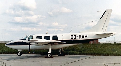
Piper Aerostar PA60-600 OO-RAP (c/n 61-0273-105)
In 1981, Piper introduced the 602P. This airplane is virtually identical to the 601P except for the engines, and they are quite different, even though the horsepower remains the same at 290 a side. The 602P has an engine turbocharger package that was designed as one unit and offers greater usable horsepower. This can be seen directly in single engine ceiling: 12,900 feet compared with 9,300 feet for the 601P. Maximum cruise was scaled back a bit from the 601P’s original number, to 245 knots. Some of this l l knot loss can be attributed to a higher maximum takeoff weight, 6,000 pounds as compared with 5,700 pounds for the original, and the rest would go to the drag of the extended wingspan.
To get more from the airplane, Piper installed more horsepower for the 700P. The basic Lycoming 540-cubic-inch-displacement engines run at higher turbo boost, developing the additional 60 hp per side. Lycoming has retained the same 1,800-hour recommended TBO. Each engine uses two turbochargers. The 700P engines counterrotate, rotate opposite the direction of other twins’; on the 700P, the prop tips rotate away from the top of the fuselage. This came from a retest of the Aerostar design that mandated an improvement in directional control when flying at low airspeeds. The directional control problem was addressed on other models by adding vortex generators, or a supplemental ventral rudder under the tailcone. The 700P also became the first Aerostar produced with cowl flaps and with intercoolers.
The 700Ps cruise number is 261 knots at 81 percent power and 25,000 feet, so, even with the extra pow¬er, not a lot of speed is gained over the 601P. Because the 700P uses fuel at 307 pph at 81 percent pow¬er, an optional additional 40 USG fuel tank was made available, and most were equipped with it, increasing maximum fuel load to 1,233 pounds, enough for a five-hour flight at relatively high power. With the extra tank, this gave a total of 1,233 pounds (205.5USG). Only 25 or these were built.
The 700 Superstar was the prototype of a stretched fuselage variant. With additional fuel capacity and increased take-off weight, registered N72TS, it first flew on 22 November 1972.
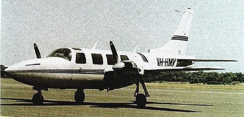
The Speedstar 850 was a modification to fit one nose mounted turboprop engine, instead of the two wing mounted engines. 25 were produced between 1983 and 1985.
Speedstar 850
The Aerostar was produced between 1967 and 1984, of the 1010 produced, 519 were built by Piper.
Aerostar 600 Engines: 2 x Lycoming IO-540, 290 hp Wing Span: 34 ft 2.5 in / 10.43 m Length: 34 ft 9.75 in / 10.61 m Height: 12 ft 1.5 in Wing Area: 170 sq ft Wing Loading: 32.3 lb/sq ft Power Loading: 9.5 lb/sq ft Baggage Capacity: 30 Cu ft, 200 lb MTOW: 5,500 lb / 2495 kg Max Zero-Fuel Weight: 4,450 lb Empty Weight: 3425 lb / 1553 kg Standard Useful: 1,700 lb Minimum Control Speed: 97 mph Best Rate of Climb Speed: 145 mph Best Rate of Climb Single Engine: 135 mph Best Angle of Climb Speed: 125 mph Best Angle of Climb Single Engine 125 mph Never Exceed Speed: 278 mph Maneuvering Speed: 187 mph Max Flap Extension Speed: 20 degrees – 180 mph, Full flaps: 148 mph Max Gear Extension Speed: 180 mph Max Gear Retraction Speed: 150 mph Max Speed at Sea Level: 260 mph Cruising Speed 70% at 10,000 ft / 3050m: 250 mph / 217 kt / 402 kph Cruising Speed 65% at 10,000 ft: 209 kts Cruising Speed 55% at 10,000 ft: 223 mph Stalling Speed: (dirty, power off) 77 mph Rate of Climb at Sea Level: 1,850 fpm / 564 m/min Rate of Climb Single Engine: 450 fpm Service Ceiling: 22,000 ft Single Engine ceiling: 6,300 ft Takeoff Distance: 1,095 ft Takeoff Distance Over 50ft: 2,120 ft Landing Distance: 932 ft Landing Distance Over 50 ft: 2,032 ft Fuel Capacity (usable): 170 USG Range (max fuel, 45 min res) max cruise, 250 mph: 1,063 sm Range (max fuel, 30 min res) 65% 10,000ft/3050m, 250 mph: 1,400 sm / 1216 nm / 2250 km Max range, 204 mph: 1,650 sm Wheel track: 10.2 ft Baggage cap: 240 lbs / 109 kg / 30 cu.ft / 0.85 cu.m Seats: 6 Vmc: 92 mph T/O dist: 1000 ft T/O dist 50 ft: 1400 ft Ldg dist: 895 ft Ldg dist 50 ft: 2420 ft Cabin length: 12 ft 6 in / 3.81 m Cabin width: 3 ft 10 in / 1.17 m Cabin height: 4 ft 0 in / 1.22 m
Aerostar 600A
similar to the 600 but with minor detail changes. Engines: 2 x Lycoming IO-540-K1J5, 290 hp TBO: 2000 hrs Props: Hartzell 3-blade CS full feathering 6 ft 6 in Wingspan: 34 ft 2 in Wing area: 170 sq.ft Wing aspect ratio: 6.9 Length: 34 ft 9.75 in Height: 12 ft 1.25 in Max ramp wt: 5525 lb Max take off wt: 5500 lb Standard empty wt: 3560 lb Max useful load: 1763 lb Max landing wt: 5500 lb Wing loading: 32.4 lbs/sq.ft Power loading: 9.5 lbs/hp Max useable fuel: 993 lb / 177 USG Baggage capacity: 240 lb Climb rate: 1800 fpm @ 122 kt Climb gradient: 885 ft/nm Rate of climb @ 8000 ft: 1150 fpm Service ceiling; 21,200 ft SE rate of climb: 360 fpm @ 113 kt SE climb gradient: 239 f/nm SE ceiling: 6300 ft Max speed SL: 260 mph / 226 kt Cruise @ 65% power @ 8,000ft: 207 kt Fuel flow @ 65% power @ 8,000ft: 185 pph Endurance @ 65% power @ 8,000ft: 5.1 hr Cruise speed 10,000ft: 250 mph Stalling speed clean: 76 kt Stall speed gear/flaps down: 74 kt Turbulent air penetration speed: 163 kt Retractable undercarriage T/O dist (50 ft): 1400 ft Ldg dist (50ft): 1950 ft Range 9000ft: 1408 mi Seats: 6
Aerostar 600AE Designation for types sold in Europe
Aerostar 601 / PA-61 Later designated PA-61 FAA approved during November 1968 for the Ted Smith Aircraft Co and on 12 April 1978 for Piper. Engines: 2 x Lycoming IO-540-S1A5, 29 hp Ceiling: 20,000 ft Max speed: 240 kts Fuel cap: 177 USG Range (no res): 1436 sm Stall, clean: 77 kts Vmc: 80 kt 117 produced.
Aerostar 601B / PA-61 Later designated PA-61 Increased wingspan, same as 601P Engines: 2 x Lycoming IO 540 P1A5 or S1A5, 290 hp TBO: 1,800 hrs Props: Hartzell constant speed, full feathering Wingspan: 36 ft 8 in Length: 34 ft 9.75 in Height: 12 ft 1.25 in Wing area: 178.2 sq.ft Baggage capacity: 240 lb Empty weight: 4031 lb Useful load: 1,969 lb Payload with full fuel: 922 lb Gross weight: 6,000 lb Maximum landing weight: 6,000 lb Usable fuel capacity: 174.5 USG/1,047 lb Wing loading: 33.6 lb/sq.ft Power loading: 9.13 lb/hp Max speed 25,000ft: 302 mph / 259 kt Max cruise, 75% power at 25,000 ft: 236 kt Econ cruise, 55% power at 25,000 ft: 212 kt Duration at max cruise: 4.8 hr Duration at econ cruise: 6.4 hr Stalling speed, clean: 79 kt Stalling speed, full flaps: 71 kt Maximum rate of climb: 1,530 fpm Single engine rate of climb: 254 fpm Single engine climb gradient 109 knots (Vyse): 141 ft/nm Certificated ceiling: 30,000 ft Single engine service ceiling: 9,250 ft Takeoff 50 ft: 2310 ft Landing from 50 ft: 2175 ft Range 25,000ft: 1435 mi Seats: 6 44 produced
Aerostar 600BE Designation for types sold in Europe
Aerostar 600P / PA-61P Later PA-61P. Produced from 1972, pressurised, increased weights and turbocharged engines. 492 produced
Aerostar 600PE Designation for types sold in Europe
Aerostar 601P Engine: 2 x Lycoming IO-540-S1A5, 290 hp Seats: 6 Wing loading: 33.7 lb/sq.ft Pwr loading: 10.2 lb/hp Gross wt: 6000 lb Empty wt: 4000 lb Equipped useful load: 1970 lb Baggage capacity: 240 lb Payload max fuel: 923 lb Range max fuel/75%: 1125nm/4.5hr Range max fuel /55%: 1304nm/6.2hr Service ceiling: 26,350 ft Max speed 25,000ft: 290 mph 75% cruise @ 25,000 ft: 247 kt Cruise: 230 kts @ 65% pwr @ 20,000ft 55% Cruise: 212 kt Vmc: 80 kt Stall: 69-77 kt 1.3 Vso: 90 kt ROC: 1530 fpm SE ROC: 285 fpm @ 117 kt SE ceiling: 9100 ft Min field length: 2047 ft T/O dist (50 ft): 2310 ft Ldg dist (50ft): 2100 ft Fuel cap: 1047 lb / 177 USG Cabin pressure: 4.25 psi
PA-60 Aerostar 602 Engines: 2 x 290 hp Lycoming Seats: 6 Empty Wt: 4125 lbs Gross wt: 6000 lbs Useful load: 1875 lbs Max Cruise: 283 mph Max range: 1260 sm
PA-60 Aerostar 602P Piper-developed version of the 601P with the 290 hp Lycoming TIO-540-AA1A5 engines First built: 1974 Engine: 2 x Lycoming IO-540-AA1A5, 290 hp TBO: 1800 hr Prop: Hartzell 3 blade, constant speed 78 in Seats: 6 Length: 34.8 ft Height: 12.1 ft Wingspan: 36.7 ft Wing area: 178 sq.ft Wing aspect ratio: 7.6 Max ramp wt: 6029 lb Max take off wt: 6000 lb Standard empty wt: 4075 lb Max useful load: 1954 lb Max landing wt: 6000 lb Wing loading: 33.7 lbs/sq.ft Power loading: 10.3 lbs/hp Max useable fuel: 993 lb Climb rate: 1460 fpm @ 117 kt Climb gradient: 749 ft/nm Rate of climb @ 8000 ft: 1320 fpm Certificated ceiling; 25,000 ft 8,000 ft cabin altitude: 20,600 ft SE rate of climb: 240 fpm @ 109 kt SE climb gradient: 131 f/nm SE ceiling: 8800 ft Max speed: 257 kts Cruise @ 65% power @ 8,000ft: 203 kts Cruise @ 65% pwr @ 18,000 ft: 220 kts Fuel flow @ 65% power @ 18,000ft: 182 pph Endurance @ 65% power @ 8,000ft: 5.2 hr Stalling speed clean: 79 kts Stall speed gear/flaps down: 77 kts Turbulent air penetration speed: 167 kts Retractable undercarriage 124 built
1981 Piper Aerostar 602P Engines: 2 x Lycoming IO 540 AA1A5, 290 hp Recommended TBO: 1,800 hrs Props: Hartzell, 3 blade, 78 in dia Length: 34.83 ft Height: 12.17 ft Wingspan: 36.67 ft Wing area: 178 sq ft Max ramp weight: 6,029 lbs Max takeoff weight: 6000 lb Empty weight: 4,406 lb Useful load: 1,623 lb Zero fuel weight: 5,900 lb Maximum landing weight: 6,000 lb Wing loading: 33.7 lbs/sq ft Power loading: 10.3 lbs/hp Max usable fuel: 165.5 USG/993 lb Certified ceiling: 25,000 ft Max pressurization differential: 4.25 psi 8000 ft cabin altitude at: 20,600 ft Max rate of climb: 1,755 fpm Max single engine rate of climb: 302 fpm Single engine climb gradient: 154 ft/nm Single engine service ceiling: 12,900 ft Maximum cruise speed, FL 250: 245 kt Cruise, 65% power at 15,000 ft: 210 kt Cruise, 65% power at FL 250: 226 kt Fuel flow at 65%: 32.4 gph, 199.4 pph Endurance at 65%, no res: 6.2 hr Stalling speed, clean: 86 kts Stalling speed, flaps down: 77 kt Turbulent air penetration speed: 167 kt
620 A pressurised Aerostar with 310 hp TIO-540 engines, one built.
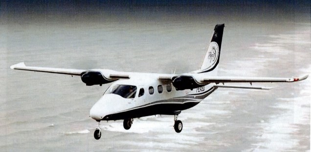
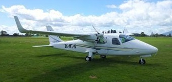
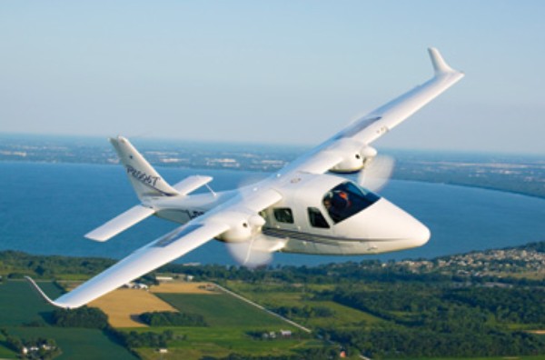
Tecnam’s P2006T was designed by Professor Luigi Pascale as Tecnam’s first twin-engine airplane. At first, Tecnam considered simply enlarging one of its existing two-seat singles to create a four-place airplane, but the company decided instead to offer an economical certified twin, targeting the multi-engine training market.
The P2006T is designed to carry a maximum of four people powered by a pair of Rotax 912S engines, rated for 100 hp each. Pascale chose the Rotax for their light weight of 141 pounds, the low frontal area of about 1.5 square feet, and the 912 is approved for autogas.
The Rotax uses a 2.43 reduction gearing to downgrade the engine’s 5,800 rpm to 2,400 prop rpm. Technically, the 912S engines are rated for 98 hp apiece on takeoff and 92 hp maximum except takeoff (METO) power. The 912S also is liquid-cooled, so it’s less susceptible to the ills of shock cooling.
The Tecnam’s gross weight is only 2,600 pounds with a 13 pounds/hp power loading and the P2006T offers a low 47-knot stall speed, this from 159 square feet of wing.
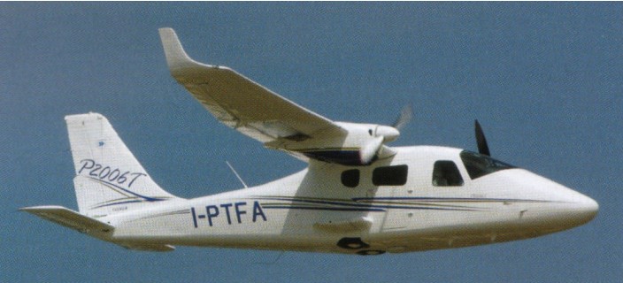
TECNAM P2006T
Pascale designed the P2006T to be constructed almost entirely of metal. The sculpted winglets atop each wingtip are molded fiberglass, but the rest of the airplane is mostly pure aluminum. Wings feature single-spar design with long-span ailerons and, as mentioned above, the big flaps reduce stall to a leisurely 47 knots.
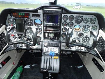
There are two doors for cabin access, a conventional left side crew door for copilot and pilot, plus an aft right side door for passengers. Entry to the front office is a simple matter of stepping in and settling into the seat.
Tecnam utilizes a standard electro-hydraulic retraction system. The trailing-link gear is mounted in pylons that extend horizontally outboard from the lower fuselage abeam the rear seats. The wheels fold into partially open wells in the bottom fuselage. Gear retraction is about six seconds up and four seconds down. Cleaned up and accelerated to 90 knots, the P2006T scores a reasonable 1,000 fpm climb at gross, 1,200 fpm at lighter weight. Single-engine climb is listed at 230 fpm. Service ceiling is 15,000 feet. The Frise ailerons are quick and the all-flying stabilator provides good pitch control in all attitudes from stall to cruise.
Tecnam lists the P2006T’s single-engine service ceiling at 7,000 feet, and coincidentally, that’s the optimum cruise altitude for the airplane with both engines running true. Cruise with everything against the stops works out to 140 knots or a bit more. Climb to 9,000 feet, where 65% is all there is, and this gives 135 knots on about 1.5 gph less fuel burn. At 65% setting, burn drops to 4.4 gph/engine, 8.8 gph total.
With a max fuel capacity just under 53 gallons, endurance at high cruise should be about four hours plus reserve, enough for 550 nm cross-countries. Tecnam’s P2006T sports good short-field characteristics. It can lift off in less than 1,000 feet of smooth, dry runway and grind to a halt in the same distance. Though the gear is retractable, the airplane sits tall on the ground, and grass strips shouldn’t present a problem.
2009 TECNAM P2006T Base price: $407,000 Engines: 2 x Rotax 912S, 100 hp TBO: 1500 hr Fuel type: 100LL, mogas Propeller: 2-blade, CS Hoffman or MT Landing gear type: Tri./Retr Max takeoff weight: 2600 lb Empty weight, std: 1675 lb Useful load, std: 925 lb Usable fuel, std: 52.6 USgal Payload, full std. fuel: 609 lb Wingspan: 32 ft. 3 in Overall length: 26 ft. 5 in Overall height: 8 ft. 8 in Wing area: 159 sq. ft Wing loading: 16.4 lbs./sq. ft Power loading: 13 lbs./hp Seating capacity: 4 Cabin doors: 2 Cabin width: 48 in Cabin height: 46 in Cruise speed, 75% power: 140 kt Cruise speed, 65% power: 135 kt Fuel consumption, 75% power: 10.2 USgph Fuel consumption, 65% power: 8.8 USgph Best rate of climb, SL: 1140 fpm Service ceiling: 15,000 ft SE climb, SL: 230 fpm SE service ceiling: 7000 ft Vso: 47 kt Takeoff ground roll: 898 ft Takeoff over 50 ft. obstacle: 1213 ft Landing ground roll: 656 ft Landing over 50 ft. obstacle: 1279 ft