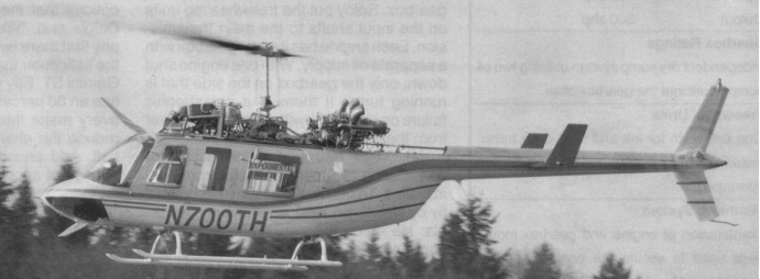
On 17 January 1991, the Tridair Gemini ST twin engine conversion of the Bell 206L LongRanger took to the air for the first time. The Gemini ST was designed to take off and hover at gross weight at sea level on one engine; the only twin engine helicopter that will have no written procedures for a single engine failure on takeoff.
The inspiration for the Gemini ST came to Doug Daigle, president of Tridair Heli¬copters in Costa Mesa, California, in 1986 when he successfully bid on a US Forest Service contract for a Bell LongRanger to be used as a rappelling platform for fire¬fighters.
This was the first time a single engine helicopter had been awarded this contract. The work had previously been done by a Bell 212, but this aircraft had become very expensive to contract, leading the Forest Service to look at the safety records of single engine helicopters and find the Bell LongRanger’s to be outstanding.
After Doug Daigle rappelled out of the helicopter to see what the fire crew would experience (an act he regrets to this day), he concluded that if the engine failed while the crew was rappelling, they would prob¬ably die. Even using a 212, the crew on the rope would be severely injured or killed. The 212 might be able to recover, but the team on the rope would be dragged through the trees or rocks. Mr Daigle then decided to try to design a twin engine conversion for the Bell LongRanger. While several people, includ¬ing from Bell Helicopter, had the same idea in the past, he took a different approach in wanting to design a helicopter that would take off on one engine at sea level at gross weight. The Bell TwinRanger project in¬volved a complete redesign that would weigh almost 1,500 lb more than the LongRanger, weight that caused the project to be shelved.
The first major obstacle overcome for the project was in 1988 when the FAA awarded the programme a grant of exemption. FAA regulations state that any time the number of engines or rotors is changed a new Type Certificate must be obtained. This would have cost many millions of dollars. The only time an exemption can be issued is for public safety and/or public economics. The Gemini qualified on both grounds.
Internally, the Soloy Dual Pac gearboxs have independent dry sump system utilising two oil pumps built into the gearbox case. Freewheel Units One unit each for left and right drive trains, ensuring minimum drag during single engine operation. Mounting System Combination of engine and gearbox mount pads used to secure the engines/gearbox assembly to the airframe. With one engine shut down, only the gearbox on the side that is running turns. If there is a catastrophic failure on one side it will not interrupt power from the good side.
Separate fuel systems for each engine had to be installed. The conversion also demanded a new cowling that incorporates dual oil coolers, blowers, and oil reservoirs.
The flight testing process began in February 1991.
The Gemini ST was certified by the US FAA to operate on one or both engines in all phases of flight.
206L-3ST Gemini ST Engine: 2 x Allison 250-C20R Instant pwr: 335 kW Rotor dia: 11.3 m MTOW: 1820 kg Payload: 570 kg Max speed: 130 kts Max cruise: 110 kts Max range: 745 km HIGE: 10,000 ft HOGE: 6,900 ft Service ceiling: 10,000 ft Crew: 2 Pax: 6 Seats: 8
206L-3ST Gemini ST Engine: 2 x Allison 250-C20R Instant pwr: 335 kW Rotor dia: 11.3 m MTOW: 2020 kg Payload: 770 kg Max speed: 130 kts Max cruise: 110 kts Max range: 465 km HIGE: 20,000 ft HOGE: 16,400 ft Service ceiling: 20,000 ft Crew: 2 Pax: 6 Seats: 8
BELL SDP H500A 206L 3ST Engines: 2 x Allison 250 C20R, 435 shp each Gearbox ratings Input (each side) 450 shp, Output 500 shp Seating: 7 Fuselage Length: 33ft 2.6in Overall Length: 42ft 8.5in Overall Height: 10ft 3.8in Rotor Diameter: 37ft Blades: 2 x semi rigid teetering all metal Max. Gross Weight: 4,450 lb Empty Weight: 2,590 lb Useful Load: 1,860 lb W/full fuel: 1,110 lb Max External Load: 2,000 lb Vne: 150 mph Cruise: 135 mph Max. Rate of Climb: 1,340 fpm Fuel Capacity: 750 lb 110 USgal Avg. Fuel Consumption: Single Engine 26 USgph, Twin Engine 42 USgph HIGE: 16,500 ft HOGE: 7,500 ft Service Ceiling: 20,000 ft
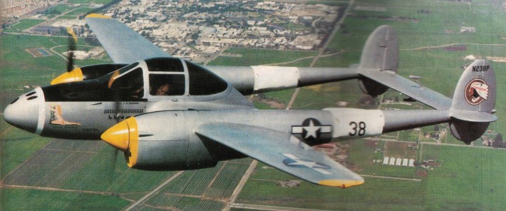
Walter Treadwell decided to design and build his own P-38 as a 55% scale replica. Treadwells is a P-38J.
Cooling the engines are four custon built copper radiators installed in the tail booms, made to form fit within the contours. Designed by Treadwell, the cores were fabricated by a Livermore radiator shop, and a friend, Norm Daniel braied the copper. Small, bullet shaped intakes provide airflow, where the supercharger air intake was on the original.
Contra-rotating was not feasible and each engine uses a 2.37-1 cogbelt PSRU reduction gearbox designed by Reductions Inc, and turns a 3 blade 66 in Warp Drive ground adjustable prop. Exhaust is through a single stack that exits below each engine nacelle.
Each part of the undercarriage was independently machined from solid stock. That included oleos, linkages and wheel forks, attachment fittings and retraction mechanism.
Although the replica is mostly composite construction, plywood was used to establish the cross sections, then stripped with foam that was then sanded into shape. Over this, fibreglass was laid, and when finished, the plywood formers removed, then replaced with bulkheads of honeycomb/glass that were glassed into the shell.
The twin booms are built the same way, but they are connected to wood stringers, then formed with foam, then wrapped with fibreglass.
The main spar is a box type built of Douglas fir in three sections. A centre section that connects the fuselage pod to each boom and the outer panels. All are covered, cap-stripped with carbon fibre, wrapped with fibreglass, then vacuum bagged. Ribs are traced from a CAD program onto full size templates, then each is individually cut from Bluefoam using hot wire. Each is then finished with ply cap strips. The aerofoil begins as an NACA 23015 at the root, then tapers into an NACA with washout at the tip of the entire wing, then covered with 1/16 inch plywood over which fibreglass cavering is applied. The control surfaces are statically balanced.
Primary controls are operated through a complex system of cables, pushrods and fittings that run from the fuselage and wings through the booms to move the ailerons, flaps, elevators, rudders and trimtabs. All this requires 34 sheaves out to the booms to accomplish this. The ailerons are controlled buy a series of bell cranks activated by cables and pushrods, and the same for the elevator. The rudders are cable controlled.
The landing gear is hydraulically operated.
The result is an airplane stressed to 9.9G. The landing gear has been drop tested for a 2000 lb landing weight.
The canopy frame is identical to the original P-38, complete with a flat forward panel, while the sides are molded. The canopy slides fore and aft to facilitate entry into the cockpit for two, and the top panel swings up and rearward.
Unlike the real P-38, Treadwell’s has a stick (topped off with an F-4 Phantom grip) to simplify linkages.
A major problem has been the engine/propeller combination with only 70% of the engine output being achived. Treadwell made the decision to ground the P-38 and replace the Suzuki engines with a pair of Walter Loms.
Engines: 2 x Suzuki 1.3 lt 4-cyl, 100 hp at 6400 rpm Wingspan: 30.6 ft Length: 21.9 ft Wing area: 110 sq.ft Empty weight: 1500 lb Gross weight: 2000 lb Cruise: 150 mph TAS Top speed: 200 mph TAS Service ceiling: 12,000 ft Range: 525 sm
The association between France and Germany that has produced the Transall began when the German aircraft industry built the Nord 2501 Noratlas under licence for the Luftwaffe. The successful co-operation between the Weserflugzeugbau GmbH and Nord Aviation on the Noratlas programme led to both companies studying a follow-on project for this old-fashioned twin-boom piston-powered medium transport. The “Transporter-Allianz” was formed in January 1958 by the participating companies, Transall being an abbreviation of the name, while the letter “C” stood for “Cargo” and the figure “160” for the equivalent wing area of 160 square metres. The joint team designed a tactical cargo and troop transport in the 50-ton category to fulfil the joint requirements of the French and German forces, with the capability of hauling a 17,600-1b (8 000-kg) payload out of semi-prepared fields over a radius of 750 miles (1200 km) without refuelling.
After several individual concepts had been studied separately in both countries, the Transporter Allianz concentrated on a shoulder wing design with two Rolls-Royce Tyne 20 Mk 22 turboprops of 6,100 eshp each, with a rear loading ramp and a kneeling landing gear to lower the fuselage for loading. According to the bi-national contracts signed in December 1959 and March 1960, the R & D costs were to be divided equally between France and the Federal Republic of Germany while each country would pay for the number of aircraft ordered for its specific needs, and final assembly lines would be established in each country.
The first prototype, the C-160 V 1, was assembled in France and made its maiden flight on 25 February 1963 at Villaroche, the V2, assembled by VFW Fokker, following exactly three months later at Lernwerder; the V3 flew on 19 February 1964 in Hamburg, (two separate assembly lines having been set up in Germany by MBB and VFW). Also in 1964, the airframes for static and dynamic tests were completed. An additional six pre-series aircraft were built before production started, with the first delivery on 2 August 1967. France had meanwhile ordered 50 Transalls (C- 1 60F), Germany ordered 110 (C-160D), 20 of these being later passed to the Turkish Air Force (as C-160T), and the Republic of South Africa bought another nine (C-160Z). The six pre-series aircraft were divided between France and Germany.
As far as the production breakdown is concerned, Nord Aviation was responsible for the wings and engine nacelles, Hamburger Flugzeugbau (HFB) built the front and rear sections of the fuselage and Vereinigte Flugtechnische Werke (VFW) the central fuselage and the horizontal tail surfaces. Some wing parts and the flaps were sub-contracted to Messerschmitt and Siebel ATG while Dornier built the vertical tail surfaces. The Messier-designed landing gear was coproduced with Liebherr-Aerotechnik. Rolls-Royce cooperated with Hispano-Suiza (now a branch of Snecma, France), MAN (later Motoren- und Turbinen-Union, Munich) and FN (Belgium) in manufacturing the Tynes. Ratier-Forest in France produced the big 18-ft (5,49-m) diameter four-bladed de Havilland propellers and Normalair (UK) delivered the pressurisation and air conditioning systems. VFW was the lead company in the programme.
The shape and dimensions of the fuselage were essentially designed to conform with the “International Railway Loading Gauge” over the entire length of the hold. The length of the compartment including the ramp is 56 ft 6 in (17,21 m), the useful width is 10 ft 4 in (3,15 m) and the max useful height 9 ft 9 in (2,98 m). The floor area is 583,9 sq ft (54,25 sq.m), giving a usable volume of 4,940 cu.ft. (140 cu.m).
Thus, a total of 178 Transalls had been produced when the last aeroplane rolled off the assembly line in October 1972. Deliveries totalled 52 C 160F for the Armee de l’Air (four modified as 160P civil night mail transports), 110 160D for the Luftwaffe (20 later transferred to the Turkish air force and 32 stored) and nine 160Z for the South African Air Force.
51+02 LTG-63 Hohn A/B, Dec 1986
The Transall C-160 was designed for flexible payload-range capabilities and stringent mission requirements. These include high gust and manoeuvre loads of 3 g at low level, as well as high static loads on landing gear and structure encountered in rough, semi-prepared field operations. The fuselage is built in three units, with the usable section designed for an operating pressure of 4.7 psi. In the centre section of the fuselage, seven main wing-fuselage frames made of forged and plate components carry the loads from the wing and the landing gear. The fuselage skin is stiffened by extruded Z section stringers. Heavy corrugated aft-fuselage frames in the tailplane take up the forces from the tail unit and the aft upward hinged cargo door.
The wing comprises three major components, a parallel chord centre section to which are bolted two tapered outer panels. The primary structure is a wing torsion box with two shear-web spars to which are attached the leading- and trailing-edge sub-assemblies. The upper and lower wing skin panels are stiffened with longitudinal extruded T-section stringers. Double-slotted flaps, spoilers, airbrakes and ailerons make up the moving surfaces of the wing. The tail unit consists of a three-spar, fully cantilevered horizontal stabiliser and a three-spar fin torsion box with stiffened skin construction. Elevator and rudder are of the same conventional construction. The dorsal fin consists of aluminium sandwich flat panels.
The main landing gear has eight wheels, with two tandem pairs of wheels on each side. Together with low pressure (55 psi) tubeless tyres sized 15.00-16, the resulting single wheel loads provide the aircraft with an excellent ability for operations from semi-prepared or unprepared strips. The twin-wheel low pressure (45 psi) nose gear is hydraulically steerable through 55 deg each side. To ease loading procedures from ground or low levels, the main landing gear may be kneeled, ie, partially retracted, thus changing the ramp slope-angle with respect to the cargo compartment floor-line. The system is operated by special built-in shock absorber-jack cylinders through power supplied by one of the engines, APU or hand pump.
Aerospatiale, MBB and VFW, decided in May 1976 to reinstate the production of the twin-turboprop Transall C-160 tactical transport. The French Armee de l’Air was at that time showing interest in buying 25-30 aircraft, and an industrial agreement was signed on 29 October 1976, it being then estimated that an order backlog of at least 75 aircraft would be needed to make the new programme an economic worthwhile enterprise.
The French Government therefore decided in July 1977 to approve the launching of the second series of the Transall C160 and ordered 25 aircraft for the Armee de l’Air. The only large aeroplane in Europe to be built on a re-established production line, having been designed in the mid-‘fifties.
Under the new industrial agreement for the second series, rather different arrangements have been made, there being no main contractor. Aerospatiale and the two German manufacturers VFW and MBB – all three original members of the Transporter-Allianz having changed their status as a result of mergers in the last decade – share the work on a fifty-fifty basis, now with a single assembly line at Toulouse. Aerospatiale is building the wings, fuselage doors, emergency exits and engine nacelles. The manufacture of the front and rear fuselage sections including the loading ramp and the dorsal fin is undertaken by MBB. VFW (itself now in process of merging with MBB) produces the centre fuselage, main landing gear fairings and all main tail surfaces. Unchanged from the previous arrangement is the share of production of the Tynes, jointly manufactured by Rolls-Royce, Snecma, MTU and FN. As in the Airbus programme, all the major airframe parts are airlifted from the manufacturing centres in Germany to Toulouse in a Super Guppy transport, for final assembly and flight testing.
No major modifications have been incorporated in the C160 design, but the list of changes in many details is quite impressive. The forward side loading door is deleted and the deicing system improved. Minor changes affect the landing gear as well as the cargo handling system. New bonding techniques are applied and corrosion protection is improved. Structural provisions are made for additional fuel tanks in the wing centre section to allow for a total of 6,170 Imp gal (28 050 lt) instead of 4,190 Imp gal (9 050 lt) with the original outer wing tanks only. This not only provides for an extended range of 4,780 nm (8 854 km) for ferry flights, but also sufficient fuel capacity for aerial refuelling tasks which are new for the aircraft. Ten of the 25 new Transalls are to be equipped with hose and drogue in-flight re-fuelling systems in the lengthened port main landing gear fairing, to serve as tankers; another five will have provision for this equipment and can be rapidly adapted to the tanker role if required. All the 25 aircraft can be refuelled in flight, using a 13 ft 1.5 in (4-m) long probe installed above and behind the flight deck.
The flight deck is designed for operations by a crew of three. As an optional extra it accommodates a swivelling seat for special tasks. The exceptionally spacious flight deck also has two berths in addition to the crew seats. The field of vision from the pilot’s position is 243 degrees.
Although the Transall C-160 is specially designed for carrying troops and cargo, it is also capable of fulfilling a variety of other missions. With a maximum payload of 3 5,270 lb (16 000 kg), the range is 1,000 mls (1850 km), increasing to 2,750 mls (5 100 km) for a payload of 17,640 lb (8 000 kg); the maximum range for ferry flights is 4,780 mls (8 850 km). Fuel consumption with both engines operating varies from 2, 100 lb to 2,755 lb (950 kg to 1250 kg) per hr and the manufacturer claims that this figure is about 30 per cent better than its competitors on a given mission.
As a cargo transport, a variety of heavy or outsized loads can be carried. This includes most military vehicles, airmobile tanks, armoured cars, missiles, partially disassembled helicopters and aircraft. An automatic latching system and easily adjustable rails and rollers permit quick-loading of pallets in standard sizes such as 88 in x 125 in (2,24 m x 3,18 m), 88 in x 108 in (2,24 m x 2,74 m), etc, standard inter-model 8 ft x 8 ft (2,44 m x 2,44 m) containers as used on trucks, railways, ships and wide-body aircraft, or 12 LD3 containers. Reinforced vehicle treadways allow for carrying vehicles with axle loads of up to 11,023 lb (5 000 kg) and freight loads of up to 205 lb/sq ft (1000 kg/sq.m). Air dropping of heavy loads (up to 17,640 lb/8000 kg single loads) is possible either by gravity release or parachute extraction.
Deliveries of the Transall C-160 (Second Series), which first flew on April 9, 1981, were completed in 1985. The sole military customer was the French Air Force, which ordered 25 with updated avionics, a strengthened wing centre section incorporating an additional fuel tank, and in-flight refuelling capability. Ten are equipped as dual-role single-point tankers, and five more have the necessary modifications to allow rapid conversion to the tanker role. In 1982 four additional aircraft were ordered for the French Air Force, two as secure communications relay platforms known as C-160A Astarte for the nuclear deterrent force from 1987, and two Gabriel electronic intelligence aircraft.
C.160 Type: tactical transport Crew: 3 Engines: two 6,l00-ehp (4,549-kW) Rolls-Royce Tyne RTy.20 Mk 22 turboprops Props: Ratier Forest built BAe Dynamics 4 blade constant speed feathering, reversing, 21 ft 4 in (6,50 m) dia Maximum speed 319 mph (513 kph) at 16,000 ft (4,875 m) Cruise speed: 510 kph Initial climb rate 1,300 ft (396 m) per minute Single engined climb rate, 300 ft/min (1,51 m/sec) Service ceiling 27,000 ft (8,230 m) Single engined ceiling, 10,000 ft (3 050 m) Range 1,150 miles (1,853 km) with max payload Range 5100 km with 8,000 kg Max ferry range, 4,780 nm (8 858 km) Empty weight 63,935 lb (29,000 kg) Maximum take-off 112,435 lb (51,000kg) Wing span 131 ft 3 in (40.00 m) Length 106 ft 3.5 in (32.4 m) Height 38 ft 2.75 in (11.65 m) Undercarriage track, 16 ft 9 in (5,10 m) Wheelbase, 34 ft 4.5 in (10,48 m) Wing area 1,722.3 sq ft (160 sq.m) Payload: 93 troops, or 88 paratroops, or 62 litters and four attendants, or 35,273 lb (16,000 kg) of freight Air refuel: Yes T/O run: 715 m Ldg run: 550 m Basic fuel capacity, 4,190 Imp gal (19050 lt); optional wing centre section tanks for 1,980 Imp gal (9 000 lt)
C-160 Srs.2 Engines: 2 x Rolls-Royce/Snecma/MTU Tyne RTy 20 Mk 22 turboprops, take-off rating 6,100 eshp each at SL, ISA, and 5,950 eshp at SL, ISA + 22 deg C; water/methanol injection system Fuel capacity, outer wings only, 4,190 Imp gal (19 050 lt), total with centre wing tanks, 6,170 Imp gal (28 050 lt) Props: four-bladed Ratier-Forest (under HSD-licence) fully feathering and reversible Prop diameter, 18 ft 0.5 in (5,50 m) Garrett AiResearch GTCP 85-160 APU, max continuous rating, 200 shp Max operating, speed, VMO 277 kts (513 km/h) CAS MMO, M = 0.64 Initial rate of climb (at 108,355 lb/49 150 kg, SL, ISA); 1,360 ft/min (6,9 m/sec) Max operating altitude, 30,000 ft (9 145 m) Take-off run (at 108,355 lb/49 150 kg, SL, ISA), 2,100 ft (6 400 m) FAR take-off field length, 5,600 ft (1707m) Landing run (MLW, SL, ISA), 1,400 ft (427 m) FAR landing field length, 4,950 ft (1509 m) Max range (at MTOW) including reserves for 5% initial fuel + 30 min: 1,000 nm (1850 km) with max payload of 35,273 lb (16 000 kg), 2,750 nm (5 094 km) with payload of 17,637 lb (8 000 kg) Max range with outer wing fuel only, 3,430 nm (6 353 km), with centre section tanks, 4,780 nm (8 854 km). Max take-off weight, 112,434 lb (51000 kg) Max landing weight, 103,615 lb (47 000 kg) Max zero fuel weight (2.5 g factor), 99,206 lb (45 000 kg), (3.0 g factor), 81,570 lb (37 000 kg) Minimum operating weight empty, 61,728 lb (28 000 kg) (plus 440 lb/200 kg for centre wing tanks) Span, 131 ft 3 in (40,00 m) Length, 106 ft 3.5 in (32,40 m) Height, 28 ft 2.5 in (11,65 m) Wing area, 1,722 sq ft (160,00 sq.m) Accommodation: Flight crew of three Cabin floor area, 584 sq ft (54,25 sq.m) Cabin volume, 4,944 cu ft (140,00 cu.m)
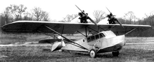
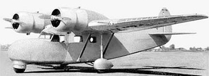
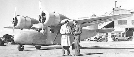
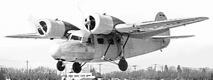
A 1931 eight-passenger high-wing cantilever monoplane amphibian flying-boat, it was powered by two 225hp radial Packard DR-980 diesel engines mounted on muitistrut pylons on the wing upper surface. The TA-3 received certification ATC 2-291.
Towle TA-2 was built as a successor to the WC model. In 1930 one was built, NX491H, powered by two 240hp Wright Whirlwind J-6 on a faired housing and wing struts were omitted. Only the one was built.
Engines: 2 x Wright Whirlwind J-6, 240hp Wingspan: 56’0″ Length: 42’0″ Useful load: 2257 lb Max speed: 120 mph Cruise speed: 100 mph Stall: 55 mph Range: 500 mi
Thomas Towle was an engineer who had been involved with many early aircraft designs. Having just co-designed the Eastman E2 Sea Rover, Towle was commissioned by Henry McCarroll to promote Detroit’s aviation production capabilities.
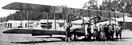
The 1928 Towle WC was built for businessman H G McCarroll and USN Lt George Pond by a group of Detroit engineers under the direction of Towle. An all-metal wing design (Towle F-2) essentially eliminated ribs and spars with its unique, internal zig-zag pattern of corrugated aluminum as a framework. The covering also was corrugated sheet aluminum. Wings were strut-braced. One WC was built, NX7956.
Priced at $25,000, the WC flying boat was first flown in November 1928. The prototype WC flew as far as Brazil before engine reliability issues forced the cancellation of the round-the-world flight attempt.
The 1930 TA-1 was the first production version of the WC with 150hp Comet engine. The one bult was registered NX5328.
WC Engines: 2 x Comet, 150hp Wingspan: 52’0″ Length: 35’0″ Useful load: 11,670 lb Max speed: 115 mph Cruise speed: 95 mph Stall: 45 mph Range: 350 mi Seats: 6
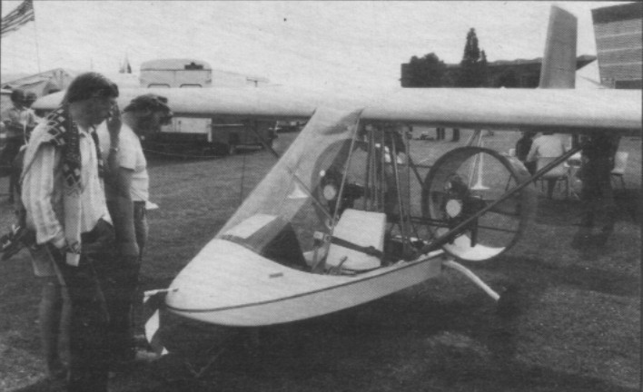
Single seat single engined high wing monoplane with conventional three axis control. Wing has unswept leading and trailing edges, and constant chord; flaps fitted. Conventional tail. Pitch control by elevator on tail; yaw control by fin mounted rudder; roll control by 39% span ailerons; control inputs through stick for pitch/roll and pedals for yaw. Wing braced from below by struts; wing profile Wortmann FS67 170 17; 100% double surface. Undercarriage has three wheels in tricycle formation; no suspension on nosewheel and glass fibre suspension on main wheels. Push right go right nosewheel steering connected to yaw control. No brakes. Aluminium tube framework, with pod. Engine mounted below wing, driving pusher propeller. Flying surfaces use foam/glassfibre/epoxy composite construction, not press moulded, with covering of rip stop reinforced Mylar.
In concept the Tirith Firebird is more of a mini aeroplane than a microlight. Designed by J Webb and Prof D Howe, both of Cranfield College of Aeronautics. Controls and flying surfaces are all thoroughly conventional and aircraft release materials have been used in all critical areas. There are no control cables, push rods being used instead. Moreover, the Firebird is fitted with 60% span flaps.
In 1982 the aircraft was still being tested and still at prototype stage.
This single seat microlight is a three axes design powered by two Weslake WAE342 engines. Firebird has a rigid composite structure, but Tirith Microplane is at pains to point out that only approved materials are used for critical areas. The Firebird was designed for Tirith Microplane by Cranfield’s Prof Hower and J. H. Webb.
Initial trials following the first flight in October 1982 found the single engine under some strain. This led to the prototype being cannibalised to provide the foundation for a twin engined machine. The powerplants are mounted side by side behind the pilot, and slightly forward of the trailing edge of the high wing. Shrouds surround the 30in diameter propellers, which are driven directly by Weslake twin cylinder two-stroke engines giving 45 hp. Flight testing was in the hands of Angus McVitie.
Engine: NGL WAE342, 25 hp at 5000 rpm Propeller diameter and pitch 36 x 16 in, 0.91 x 0.41 m No reduction Max static thrust 118 lb, 54 kg Power per unit area 0.16 hp/sq.ft, 1.8 hp/sq.m Fuel capacity 4.8 US gal, 4.0 Imp gal, 18.2 litre Length overall: 18.5 ft, 5.65 m Height overall: 8.7ft, 2.64m Wing span: 29.1ft, 8.86m Constant chord: 5.2ft, 1.60m Dihedral: 0 deg Sweepback 0 deg Tailplane span 11.5 ft, 3.52 m Fin height 3.4 ft, 1.05 m Total wing area 153 sq.ft, 14.2 sq.m Total aileron area 11.1 sq.ft, 1.03 sq.m Fin area 7.5 sq.ft, 0.70 sq.m Rudder area 3.1 sq.ft, 0.29 sq.m Tailplane area 20.2 sq.ft. 1.88 sq.m Total elevator area 10.4 sq.ft, 0.97 sq.m Wing aspect ratio 5.5/1 Wheel track 5.7 ft 1.75 m Wheelbase 5.8ft, 1.78 m Nosewheel diameter overall: 10 inch, 25 cm Main wheels diameter overall: 10 inch, 25 cm Empty weight 254 lb, 115kg Max take off weight 474 lb, 215kg Payload 220 lb, 100kg Max wing loading 3.10 lb/sq.ft, 15.2kg/sq.m Max power loading 19.0 lb/hp, 8.6kg/hp Load factors +4.0, 2.7 design; +6.0, 4.0 ultimate