Porte designed the F.3, a slightly enlarged variant of the F.2, which was put into production. The F.3 soon proved to be inferior in many respects to the F.2, but by the time this was realized full scale production was well under way and could not be halted. This accent on F.3 production inadvertently prevented full importance being given to Porte’s final biplane flying boat design, the F.5.
Span: 31 m (102 ft) (upper), 22.6 m (74 ft 2 in) (lower) Length: 15 m (49 ft 3in) Height: 5.7 m (18 ft 8 in) Maximum speed: 150 km/h (93 mph) at 609.5 m (2000 ft).
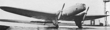
The Farman F.280 was a three engine, cantilever wing monoplane designed in France as a mail carrier in the early 1930s. The F.280 was the response to a program that aircraft to fly on two engines, without descending to an altitude equal to or greater than 1 000 m, while bearing 300 kg of mail and maintaining a speed of 145 km / h. Underpowered and slow, only two were built and briefly used.
The F.280 used an F.190 wing, though, modified to carry two of the F.280’s three engines on its upper surface; its span of 14.38 m (47 ft 2 in) made it a smaller aircraft than the near contemporary three engined F.300.
Structurally, the wing was built around two spars. Over most of the span the wings had parallel chord but the outermost section, where the ailerons were carried, tapered to straight tips. A pair of parallel aluminium struts inside streamlined spruce fairings took lift and drag loads to the lower fuselage longerons. There were additional vertical struts, small ones as on the F.190 but more sturdy ones under the outboard engines. The empennage of the F.280 was also similar to that of the F.190, with a double strutted rectangular tailplane carrying separate elevators, with a rudder cut-out between them. This deep rudder, tabbed and horn balanced was likewise square edged, mounted on a very wide chord, shallow, straight edged fin.
The F.280 had a flat sided fuselage with the pilot’s cabin under the wing, the windscreen just forward of the wings, with the third engine mounted in the nose. Square windows lit the interior. The conventional undercarriage had main legs attached vertically to the forward wing struts as extensions of the struts between the latter and the engines and with slimmer bracing to the upper fuselage longerons. Spilt axles hinged at the lower fuselage centre and radius arms from the lower longerons took the longitudinal loads. The single mainwheels were spatted.
The F.280 flew for the first time in February 1931, piloted by Jean Liron. With one of its three engines out, it could maintain altitude at 1,000 m and 145 km/h, carrying a load of 300 kg. It was slow to climb to 300 m, though, so in August 1932 the Salmson radials were replaced by the newer Renault 4Pb, aircooled, inline engines. These produced the same power but turned faster, and the resulting model F.281 was 40 kg (88 lb) lighter.
In October1932, the aircraft ended its tests, have demonstrated a speed of 182 km / h at 2000 m above sea level and 800 km range with a payload of 400 kg and 550 lt of fuel. It took off in 250 m and stops in 185 m. At full load, with a stopped engine, it climbs from 1350 m to 1750 m altitude. It achives in the first series an hour flight to 1000 meters with one engine stopped.
It was purchased by SGTA as a night mail carrier and delivered on 26th October 1932 and was tested on the Paris-Berlin route, which connected via Cologne to Sweden. Journey time was 4 h 55 min.
In mid-1933 several airlines, SGTA amongst them, joined together to form Air France. The F.280 flew little if at all with the new organisation; by 31 April 1935 it had only logged 24 hours of flight, with just 4 hours since January 1933. It never received a route certificate and was always too slow but it was used to investigate aspects of the continental network. It was equipped with dual controls to serve at the PSV for training of Air France pilots.
In the hope of higher speeds Farman built a second F.280 series aircraft, the F.282, which had 105 kW (140 hp) Renault 4Pei Bengali engines, inverted and uprated versions of those of the F.281. Despite the extra power, maximum speed was only increased by 10 km/h (6 mph). It was tested by the Société Central pour l’Exploitataion de Lignes Aériennes in July 1933, who found it precise to fly but still underpowered. As a result no more F.280 series were built and development of the two existing machines ceased. Records from Air France show the F.282 as still on their books in December 1934, but says nothing of its use.
F.280 Engines: 3 × Salmson 7Ac, 71 kW (95 hp) Propellers: 2-bladed Length: 10.50 m (34 ft 5 in) Wingspan: 14.38 m (47 ft 2 in) Height: 3.10 m (10 ft 2 in) Wing area: 40.20 m2 (432.7 sq ft) Empty weight: 1,360 kg (2,998 lb) Gross weight: 2,240 kg (4,938 lb) Maximum speed: 220 km/h (137 mph; 119 kn) Range: 575 km (357 mi; 310 nmi) Service ceiling: 5,000 m (16,404 ft) Crew: 3
F.281 Engines: 3 x Renault 4PB, 95 hp Wingspan: 14.38 m Wing area: 40.20 sq.m Height: 3.65 m Length: 10.50 m Empty weight: 1321 kg Total weight: 2200 kg Max speed: 230 kph Ceiling: 5000 m Range: 575 km Crew: 3
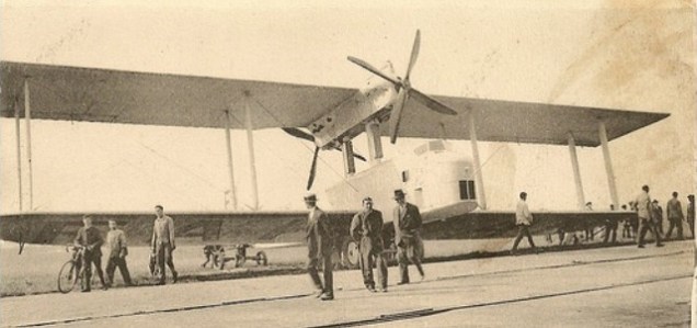
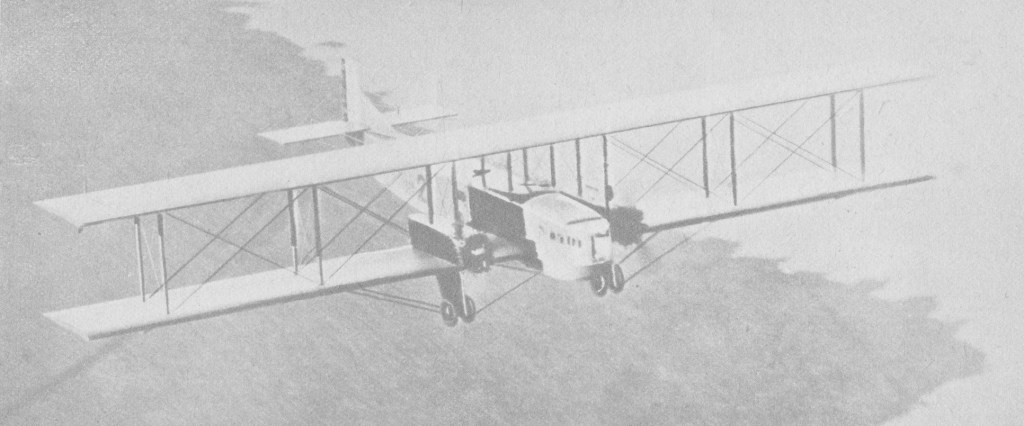
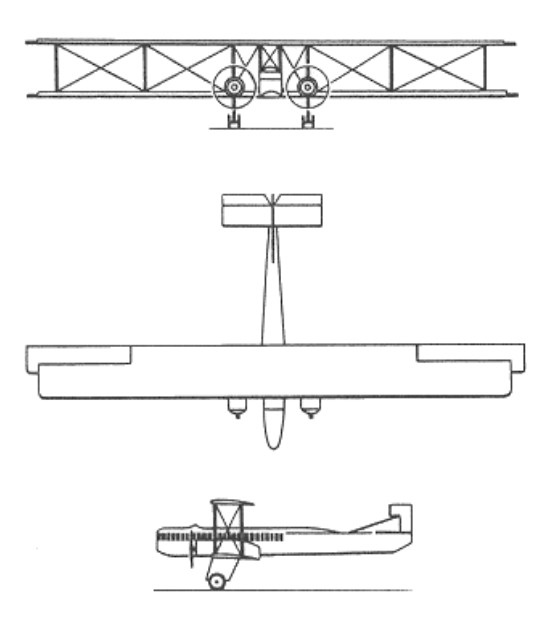
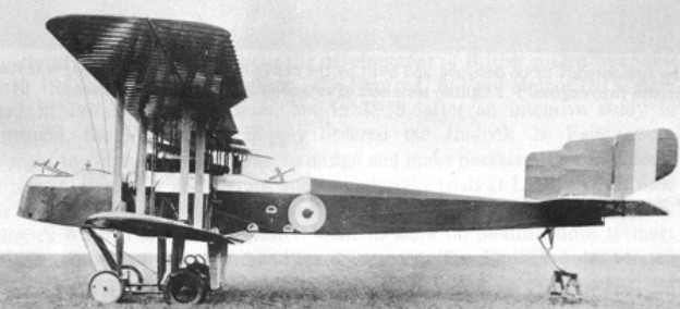
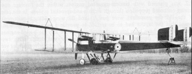
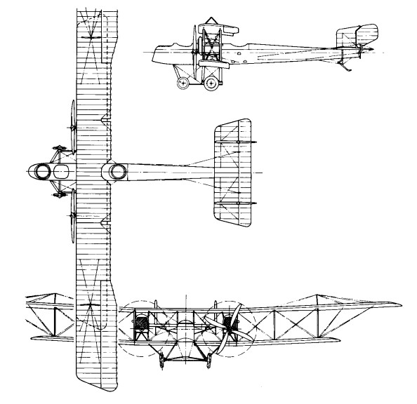
The two FF.60 bomber prototypes of 1918 started a great family of passenger airliners and night bombers. The F.60 of 1915 16 was an F.40 with the more powerful 190 hp Renault; the F.61 was the 190 hp version of the F.41. The type was an equal-span biplane with a conventional monoplane-type tail unit. The landing-gear legs had trousered fairings and each supported twin wheels. Immediately above each leg was an engine set in a large nacelle on the lower wing, with minimal clearance between the propeller and the slab-sided fuselage.
Bomber versions had gunners cockpits in the nose and amidships, while the pilot and co-pilot/navigator were seated in tandem in open cockpits. Commercial transport Goliaths had a nose cabin for four passengers and an aft cabin for eight, separated by a raised open cockpit for the two pilots under the leading edge of the upper wing.
The Farman brothers commenced Paris-London flights on 6 February 1919 using an F.60 Goliath.
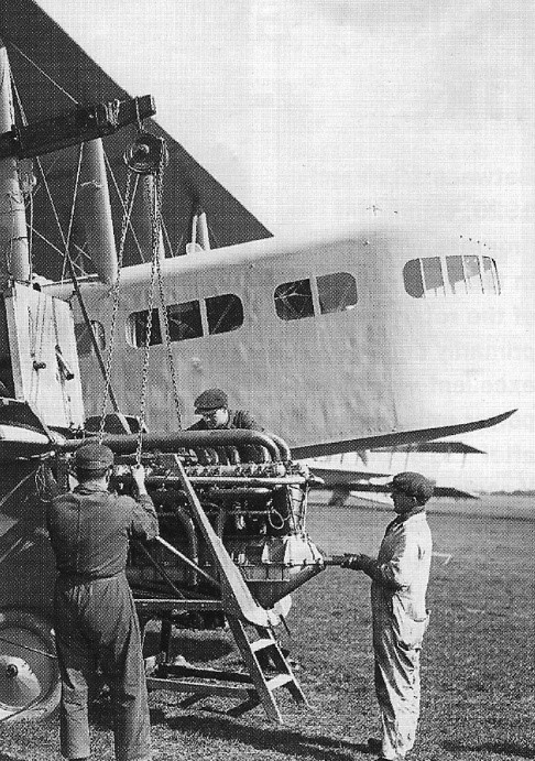
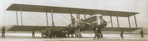
Renault 300 hp on a Farman 60
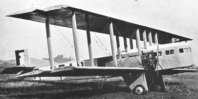
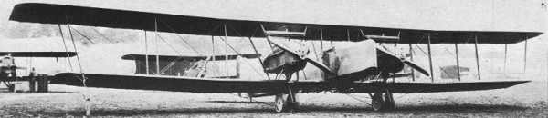
About 60 commercial Goliaths were built in several versions with Salmson, Renault, Lorraine, Gnome-Rhone-built Jupiter, Armstrong Siddeley Jaguar and Farman engines, among the most important being those powered by 171.4kW Salmson Z.9 radial engines operated by Air Union.
Goliath – Armstrong Siddeley Jaguar engines
Several flew with other airlines including the Farman airline, and indeed it was this company that started the world’s first regular international passenger service, beginning on 22 March 1919 between Paris and Brussels. Of course this had not been the first international passenger service by an airline between European capital cities, this being officially recognised as the Farman flight between Paris and London on 8 February 1919 carrying military personnel. However the latter was not the start of a sustained or civil passenger service and as such does not conflict with the Paris-Brussels “first”. Versions operated by the Farman airline included the Renault-powered F.61 and Gnome-Rhone-built Jupiter-powered F.63bis. Six passenger-carrying Goliaths were also built under licence in Czechoslovakia, two going to the air force.
F.60
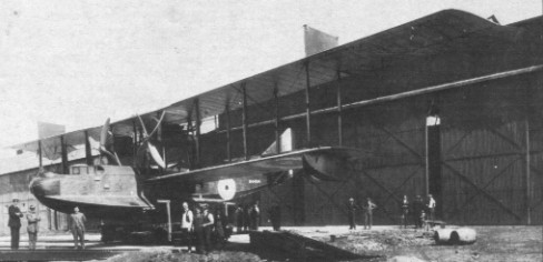
Thirty-six F.60 bombers (with Salmson engines and cut-down noses) served with the French 21 and 22 Regiments d’Aviation and 24 square-nosed Jupiter-powered Goliaths equipped naval escadrilles 6R1, 6B1 and 6B2, following tests with a passenger type. These could be mounted on twin floats (with stabiliser floats under the lower wings) as an alternative to the normal wheel-type landing gear. Russia purchased sufficient F.62s to equip two units which formed the embryo of its new heavy bomber force; Japan and Italy bought a single example each for testing; and Poland acquired 32 F.68 bombers. Export bombers – like the 42 F.63 for the French Army and a large batch of F.65 for the French Navy – each had a ‘balcony’-type nose-gunner’s cockpit with a ‘step’ below. The Belgian Aviation Militaire had two squadrons of F.41s and 60s a few F.40 series were used by the RNAS and 30 were supplied to the American Expedtionary Force. Conversions to airliner were operated by Air Union circa 1929.
Engine: 2 x Salmson CM.9, 190kW Max take-off weight: 4870 kg / 10737 lb Empty weight: 2500 kg / 5512 lb Wingspan: 26.5 m / 86 ft 11 in Length: 14.3 m / 46 ft 11 in Wing area: 161.0 sq.m / 1732.99 sq ft Max. speed: 130 km/h / 81 mph Cruise speed: 120 km/h / 75 mph Ceiling: 4000 m / 13100 ft Range w/max.fuel: 400 km / 249 miles Crew: 2 Passengers: 12
The F.50 bomber was a large tractor machine able to carry a significant load of heavier bombs. It was normally powered by two 250/265 hp Lorraine Dietrich engines, and in appearance strongly resembled the enemy Gothas. The front gunner/ bomb aimer was in the nose and the pilot just ahead of the wings; there was no rear cockpit for a gunner to provide defence astern. There were two twin wheel landing gears, between which were racks for eight 75 kg (165 lb) bombs. Two escadrilles of the Aviation Militaire used this type, and two were supplied to the AEF. The F.50BN 2 operating as a night bomber in 1918. Several survived for some years with the French navy (as torpedo bombers), in Japan and as civil transports.
Span: 22.9 m (75 ft 1.5 in) Length: 12.03 m (39 ft 5.75 in) Gross weight: 3116 kg (6870 lb) Maximum speed: 150 km/h (93 mph)
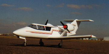
The MASTER X has been in conceptual development for a number of years. It was conceived to be a different kind of home built aircraft seating two in tandem. The philosophy of being different is consistent with earlier designs. STOL (short take-off & landing) like performance, combined with the retractable landing gear for maximum efficiency and powerful twin engines mounted on pods aft of the cabin or a single engine in fuselage with belt-driven props.
With the concept of the convertible helicopter proved on a small scale with the Jet Gyrodyne, the proposal put forward by Dr. J.A.J. Bennett and Captain A.G. Forsyth in 1947 for a large compound helicopter looked viable, and various designs were considered. The first mention of the project and of the name Rotodyne was made in March 1951 by the Ministry of Civil Aviation’s Interdepartmental Helicopter Committee in its initial report. No details were given, but it was reported to have two propeller-turbines and tip-jets, to have a cruising speed of 217km/h and capacity for 23 passengers. This was probably the Mamba-engined project.
Confirmation of the need for such an aircraft was provided by the British European Airways specification of December 1951 for a short/medium-haul ‘BEAline Bus’. Five manufacturers submitted projects to meet this earlier specification for a 30/40-passenger aircraft. Fairey’s original proposal again incorporated the projected D.H. powerplants. These were in two underwing nacelles, in each of which was located a main gas-turbine driving an auxiliary compressor and, mounted in tandem, a second turbine driving a constant-speed propeller through a reduction gear. Air for this turbine was tapped from the auxiliary compressor of the main engine. The rotor was four-bladed, with pressure-jet units at the tips.
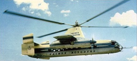
The Gyrodyne had rear clam-shell doors allowing the loading of large motor vehicles. A forward-located door permitted simultaneous entry and exit of passengers. The passenger compartment was 14m long, 2.4m wide, and 1.8m in height. The tail lower tail surfaces were oriented straight down, while the upper surfaces were canted at about a 45 degree angle. The final version, with two Elands driving propellers and/or auxiliary compressors, was outlined in 1953 and formed the subject of a Ministry of Supply research contract. This became the definitive prototype, leading later, without very fundamental changes, to the proposed production Rotodyne FA-1, or Type Z, of 1959-60, with planned seating for up to 70 passengers. For this, XH249 (F.9430), the Elands could not provide the power required, so two 5,250shp Rolls-Royce Tyne propeller-turbines were envisaged. But in hot/high conditions, even this power would have been only just adequate in the engine-failure on take-off case, and Rolls-Royce suggested separate air-producing engines to supply the tip-jets.
Fairey Rotodyne – Eland engines
The proposed solution was to install, at the rear of each nacelle, an RB.176 in which a lightweight gas-turbine drove an auxiliary compressor. By this use of separate propulsion and lift power there would be a considerable increase in weight, but the arrangement gave worthwhile gains in off-design conditions. The Fairey pressure-jet unit for the prototype consisted of a circular-section flame-tube fed by three air pipes and one fuel pipe. This was faired within a streamlined nacelle and terminated in a simple propulsive nozzle. The BEA type specification for the production Rotodyne stipulated an initial climb, at zero forward speed and maximum weight, of not less than 1823m/min, and a noise level, at a distance of 183m, of not more than 96 decibels. With the power planned for the production Rotodyne the noise level for the existing tip-jets would have been about 113 db. To achieve the necessary 17-db reduction in noise level a complete redesign of the pressure-jet was planned. This would have been in two-dimensional form, occupying the last 1.2 metres of each blade, with nine circular flame-tubes in a combustion chamber submerged within the blade profile. Much work was done on silencers, but it was never reduced to the 96 decibels that the authorities demanded.
New test facilities were set up at White Waltham in 1951 for the development of the tip-jets. These consisted initially of a test stand and a rotating rig for chamber-spinning tests. A Rolls-Royce Dart engine, with air tapped from the combustion chambers, was used as a compressor plant for the rig; two other Dart compressor plants were used for the air supply to the rotating stand. On this, a balanced single-bladed rotor, with hingeless hub, was used to investigate tip-jet light-up, regulation, performance, cooling and loads during rotation. Prior to installation on the Jet Gyrodyne, a complete rotor, including hub, blades, jet units and controls, was installed. By the end of 1953 the chamber and rotor had been developed, and the Jet Gyrodyne flew untethered for the first time in January 1954.
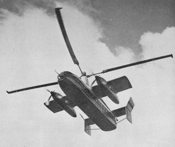
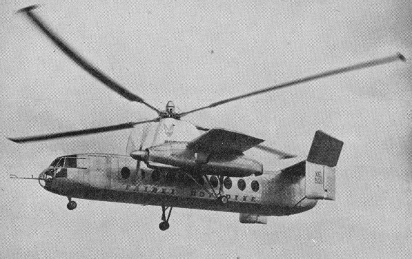
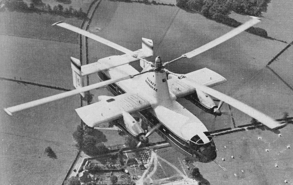
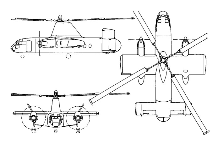
The Rotodyne was a square-section fuselage with untapered 14.17m stub wings on which were mounted two 3000shp Napier Eland turboprops for forward propulsion. The main wheels of the tricycle landing gear retracted forwards into the nacelles, and the nosewheel forwards below the cockpit. Twin fins and rudders, later joined by a central fin, were mounted on an untapered tailplane set on top of the rear fuselage. A large four-bladed rotor for vertical take-off and landing was driven by tip jets which received compressed air from the Eland engines via a compressor. To provide compressed air for the jets the two 2,800shp Napier Eland N.E1.7s operated as dual-purpose powerplants – acting either as normal propeller-turbines or as pressure-generators according to requirements. They were virtually normal Elands up to the rear of the turbine casing, where there was a nine-stage axial compressor driven by the power turbine through an hydraulic clutch. For take-off and landing most of the engine power was absorbed by the compressor, which delivered air to the internal duct system of the rotor. The small amount of remaining power of the engines went to the propellers for yaw control. In cruising flight all the power went to the propellers, with the rotor autorotating. Each engine fed air to two opposing blades so that, in the case of failure of one engine, there would be adequate pressure to keep two jets burning efficiently and giving maximum thrust.
All the earlier flying was completed with the fixed undercarriage while a revised form of retractable undercarriage, with special dampers, was designed and manufactured. This was fitted to the prototype soon after mid-year 1958 when the initial transition trials had been completed and the Rotodyne was being flown faster and for longer periods in the ‘winged autogyro’ mode.
Following the resonance and running tests, the first untethered flight of the Rotodyne, XE521 (F.9429), was made by W. R. Gellatly and J. G. P. Morton at White Waltham on 6 November, 1957, and two further flights, carrying a flight observer, were made on the first day. Originally it had been intended to keep within the ground cushion during the early flights, but the prototype was taken on a circuit of the aerodrome, well above cushion height, on one of the first three flights which were made at a weight close to the 15,000kg maximum.
Until 10 April, 1958, all flights were made in the helicopter mode. On that day, at 1220m, the first transitions were made to and from the autogyro mode and thereafter a stage-by-stage transition technique was further evolved to ensure complete safety at all moments during the manoeuvres. During the 70 earlier helicopter flights, speed had been built up to 250km/h and altitude to 2072m before transition tests were started.
In its original form the control system followed that of the Jet Gyrodyne, with direct roll and fore-and-aft control through the cyclic pitch-change of the rotor-blades; with a trimming ‘elevator’ used to select fuselage attitude (and consequently wing lift) in cruising flight; and with yaw control by differential propeller-pitch at low speeds or when hovering, and by rudders at higher cruise speeds. Early in the test programme it was found that the fore-and-aft attitude control, using the separate functions of cyclic rotor-control and elevator trim, produced some difficulties. The solution was to link the elevator to the longitudinal cyclic control for both slow and high-speed flight and to disconnect the cyclic control when cruising.
Later, when it was found that the economical cruising speed was more like 273km/h than the originally planned 209km/h, it was found that, at higher speeds, the wing was doing too much work and the rotor too little, so that the blades were flapping and the control margins were inadequate. The wing, originally set at an incidence of 4°, was re-set at 0° and fitted with ailerons, the operation of which was linked directly to the cyclic lateral control of the rotor. The outward-sloping upper fins were also moved to the vertical so as to reduce the rolling tendency with yaw. These changes produced a normal ‘aeroplane-type’ rolling control for the pilot, and the situation was further improved later by the fitting of a third upper fin.
Towards the end of 1958 a decision was made to establish a speed record with the Rotodyne. The 100km closed-circuit category was considered to be the most usefully representative of the kind of operation for which the Rotodyne was designed and that in the new convertiplane class (E.2) was chosen. On 5 January, 1959, the Rotodyne was flown by Gellatly and Morton, with Dr D. B. Leason, Fairey powerplant flight observer, and E. J. Blackburn, strain-gauge operator, as ‘passengers’, over a measured circuit between White Waltham and Hungerford, Berkshire. The flight was completed at an average speed of 307km/h – which was 79km/h higher than the equivalent record for a helicopter and nearly 48km/h higher than that for absolute speed in a straight line. At that time the Rotodyne had not yet been modified with the reduced wing-incidence and the fitting of ailerons to improve control at higher speeds. The record, which was confirmed in March, stood until October 1961, when it was beaten by the Russian twin-rotor Kamov Ka-22 Vintokryl convertiplane.
On 16 June, 1959, the Rotodyne was taken outside the United Kingdom for the first time when it was flown to Paris for the 23rd Aeronautical Salon from London’s Heathrow Airport, via the Allee Verte heliport at Brussels and the Issy heliport in Paris before landing at Le Bourget. After demonstrations there, and at Versailles for officers of the North Atlantic Treaty Organization, the Rotodyne was flown back to Heathrow.
During 1959 the wings were given ailerons and increased incidence, and the vertical tail surfaces were also revised. On 7 February 1960, XE521 resumed trials with an added central fin, shortened exhausts and a fully-faired rotor pylon.
Budgetary problems of the time saw the RAF and British Army withdraw their interest and the Rotodyne became a wholly civil project.
During 1958 the Kaman Aircraft Corporation secured a licensing agreement for sales and service in the USA with a possibility of manufacture there. Okanagan Helicopters of Vancouver was interested in three and Japan Air Lines was considering the type for domestic routes. However, the biggest potential customer was New York Airways, which joined with Kaman in a letter of intent for five, plus options on 10, for delivery in 1964. The provisional order from NYA was for the bigger-capacity, 54/65-seat Rotodyne powered with Rolls-Royce Tyne propeller-turbines and with a gross weight of 22680kg. There had been earlier references to the use of Tynes in the production version, but this order led to the first fuller statements about this version, for the development of which an additional GBP8-10 million was needed. The Government had offered to contribute half this sum, up to a certain fixed maximum, with repayment through a sales levy, but this was conditional on a firm order from BEA. Confirmation of the NYA order depended on several factors — including one that the first ‘Mk.2’ Rotodyne should be flying on test by the autumn of 1961 and another that the noise-level should be acceptable to the airline and airport authorities.
At the Paris Salon in June 1959 a model of the production version had been exhibited in the markings of New York Airways.
Fairey needed up to GBP 10 million to develop this version and was offered 50% of this by the government if BEA would place a firm order. The government contribution was to be a loan, repayable by a sales levy. In 1960 Fairey merged with Westland and although initially the Rotodyne project looked secure, it was not. In April 1960 Okanagan cancelled its order because of the long delivery dates, and five months later New York Airways expressed concern over the delay in production plans. Westland was then involved in taking over Bristol’s helicopter programme as well as with other work in hand. This, together with the ever-increasing weight of the Rotodyne, which reached a stage where the Eland could no longer be developed and the Tyne could not be afforded, led to withdrawal of government support, and the project was cancelled on 26 February 1962. On that date the British Minister of Aviation, Mr Peter Thorneycroft, said that, because of the costs involved, it was necessary to ‘forego the operational advantages’ offered by the military version, and that British European Airways, then its only potential British civil operator, had regretfully concluded that ‘the commercial prospects on their routes were not sufficiently assured to justify the heavy liabilities involved’ in placing a production order. In the absence of any firm order, Westland Aircraft did not feel justified in proceeding with the project. GBP11 million was spent during the nine years or so following the placing of the original research contract in July 1953. During the final three years of the period, however, financial support had been uncertain and the project suffered from continuing political and other indecisions which made costly forward planning impossible. The Rotodyne was subjected to a vigorous flight test program of over 350 flights, more than half of them demonstrating 200 hover-to-vertical flight transitions.
A twin 447kW Rolls-Royce Kestrel Vl-engined cantilever low-wing monoplane heavy night bomber, 14 of which were operated by the RAF from 1937 until just before the outbreak of World War II.
Engines: 2 x Rolls-Royce Kestrel IV, 440kW Max take-off weight; 9072 kg / 20000 lb Empty weight; 5774 kg/ 12730 lb Wingspan; 31.0 m / 101 ft 8 in Length; 18.5 m / 60 ft 8 in Height; 5.6 m / 18 ft 4 in Wing area; 110.0 sq.m / 1184.03 sq ft Max. speed; 249 km/h / 155 mph Cruise speed; 215 km/h / 134 mph Ceiling; 6500 m / 21350 ft Range w/max.fuel; 2200 km / 1367 miles Range w/max.payload; 1900 km / 1181 miles Armament; 3 machine-guns, 1100kg of bombs Crew; 5
Fairey Hendon Mk. II Engines: 2 x Rolls Royce Kestrel VI, 600 hp Length: 60.761 ft / 18.52 m Wing span: 101.739 ft / 31.01 m Max take off weight: 20003.8 lb / 9072.0 kg Max. speed: 135 kts / 250 kph Range: 1180 nm / 2185 km Armament: 3x 7,7mm MG, 753kg Bomb. int.