Agricultural aircraft, a development of Stearman Model 75 (Boeing Kaydet). Alternatively offered new high-lift wings and special modification kits. In eight years more than 200 Stearmans were fitted with new wings, permitting loads of over 2,000 Ib (907 kg).
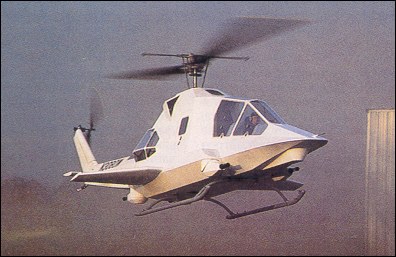
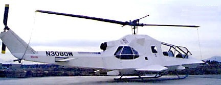
Bell UH-1B “Hueys” were stripped down to engine and transmission mounts, controls modified to tandem arrangement and re-covered with armored composite structure, containing troop-carrier compartment for six soldiers, two aft facing gunner turrets on either side of the engine and two forward facing turrets. The aircraft, named the “Penetrator”, was also outfitted with stub wings, which unloaded the main rotor in high-speed flight, increasing airspeed, and the aircraft’s aerodynamic fuselage minimizes profile drag. The basic model is an all-composite compounded helicopter with a gross take-off weight of 4280kg. To reduce the Penetrator’s drag, all the machine guns, cannons and some rocket launchers are carried internally. The “Penetrator” offers the feature of a two-seat in tandem cockpit with the pilot positioned in the first seat for unobstructed vision and two forward-firing weapons operator is in the second seat, with the third and fourth weapons operators in seats aft of the main cabin to control rear-facing weapons. This firepower allows the “Penetrator” to perform as an excellent shock assault troop lift gunship with air-to-air, air-to-ground and ground-to-ground capability. The Penetrator is fitted with a skid undercarriage (or optional retractable tricycle gear), a lower fuselage rear-facing gun turret and two forward-firing cannon. The “Penetrator” has 360 degrees of perimeter firepower and it’s composite construction of Kevlar reinforced by Nomex and the angular shape of its design afford the “Penetrator” ballistic resistance to small arms fire and low observability.
AAI Penetrator N3080W
Designed by William F Moody, the prototype (N3080W ex U.S.Army 63-8508) is powered by a 1300shp Avco Lycoming T52-L-13 turboshaft, and first flew in October 1991.
In 1990 American Aircraft fell into insolvency.
Engine: 1300shp Avco Lycoming T52-L-13 Rotor diameter: 48 ft 0 in Length: 48 ft 0 in Loaded weight: 4631 lb Max speed: 195 mph Cruise: 140 mph
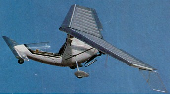
In March 1981 Romuald Drlik began the design work for a new lightweight canard-type aircraft, tentativly named Falcon and in May 1981 Romuald and helpers began construction on the first Falcon prototype (model “A”). After first trying a single-wheel gear and side-stick (neither successful) the #1 Falcon flies in late July 1981 using tricycle gear, a double-surface variable camber Dacron wing, centre hinged-stick, and a Robin 240 cc single-cylinder engine.
The Falcon’s fuselage is moulded Kevlar and graphite. The wings and canard, though constructed by standard techniques with aluminium and foam, are covered with “Tedlar”, a durable and resilient alloy of Teflon and mylar.
Falcon performance figures reach the established limits for an ultralight, with cruise speed at 60, stall at 26 and maximum at 63. Powered by a small single-cylinder, 26-hp Rotax engine, the Falcon’s highly efficient configuration affords the highest allowable performance, while the incidence angle of the canard limits excessive speed. Controls are standard three-axis, with full-span ailerons.
The Falcon was to be available as a complete, ready to fly craft, not a kit. The finished Falcon featured in-flight restarting, cockpit choke system, five-function AeroGage panel, nosewheel steering and brake, shoulder harness/seat belt, padded seat, ¾ canopy, cabin heat and choice of several fuselage colours. Projected price was $7500 (in August 1983).
In August 1981 the #2 Falcon prototype was displayed (static only) at Oshkosh and during the winter of 1981-82, the development continued on prototypes #2 and #3, altering forward wing position wing incidence, engine (changed to Cuyuna 215), wing camber, gear geometry, and rudder shape. In Jan 1982 the #3 Falcon prototype was flown in an Arizona race but DNF’s due to a reduction system failure. The empty weight of this (registered) aircraft was 215 lbs. Testing in Feb 1982 showed static loads tests on the #3 prototype go beyond 7 g’s positive and three negative before yield. In March 1982 Prototype #4 (Model 1B) was flown at the Sun N’ Fun Fly-in, using a Cuyuna 430 engine. Testing continued with Prototype #5 first flying in April 1982. Prototype #6 began flight tests July 1982, having a shorter span (31.5 feet) and a totally different wing design using a single strut, D-tube spar, and doped Ceconite wings. November 1982 brought the first flights of prototype #7 (model “C1′), using fiberglass D-tubes for wing structure, 36 ft. span, and lighter Rotax 277 engine. This craft was made in response to the release of FAR Part 103 in October of 1982, to meet the requirements of the new ultralight air vehicle category. In January 1983, prototype #7 won first-in-class at the Arizona Air Race. This same month, #7 makes flights to 13,000 feet, is flown in snowstorms and rainstorms, and flown in 25-30 mph winds. March 1983 brought first flights of prototype #8, N 918 M, incorporating 36-ft aluminum D-tube wings, all-fiberglass fuselage structure (eliminating tube-style engine and wing mount), and Tedlar wing covering. Prototype #8 won Grand Champion and Outstanding Craftmanship awards at Sun &’ Fun March 1983. During 1983, N 918 M was exhibited at many airshows, with continued flight testing in Albuquerque as well. In August 1983 three pre-production ultralight-legal Falcons were flown at Oshkosh, utilizing Kevlar-and-graphite fuselages and numerous refinements. Two of the planes were delivered to Falcon dealers. One craft won Reserve Grand Champion, then was flown home in one afternoon to Minneapolis (over 260 miles), averaging 57 mph ground speed. In August 1983, load tests to destruction were performed on the other Oshkosh plane (prototype #9, which was weighed by the EAA at 240 lbs), documenting a load-carrying strength of 7 g’s positive, three negative for the main wing and over 10 g positive 5 negative for the forward wing. January 1984 – Deliveries of production Falcons begin.
Wing has swept back leading and trailing edges, and tapering chord; no tail, canard wing. Pitch control by elevator on canard; yaw control by tip rudders, roll control by fullspan ailerons; control inputs through stick for pitch/roll and pedals for yaw. Wing braced from below by struts; wing profile; double surface. Undercarriage has three wheels in tricycle formation; steel spring suspension on nosewheel and axle flex suspension on main wheels. Push right go right nosewheel steering connected to yaw control. Brake on nosewheel. Glass fibre fuselage, partially enclosed. Engine mounted below wing driving pusher propeller. The Falcon XP two seat tandem version became available in early 1984.
Falcon Engine: Rotax 277, 28hp at 6200rpm Power per unit area 0.15 hp/sq.ft, 16.3 hp/sq.m Fuel capacity 5.0 US gal, 4.2 Imp gal, 18.9 litre Length overall 10.6 ft, 3.20 m Height overall 5.0ft, 1.52m Wing span 36.0ft, 10.97m Mean chord 4.5ft, 1.34m Canard span 10.3 ft, 3.12 m Canard chord 1.9 ft, 0.53 m Total wing area 185 sq.ft, 17.2sq.m Main wing area 165 sq.ft, 15.3sq.m Canard area 20 sq.ft, 1.9sq.m Main wing aspect ratio 7.9/1 Wheel track 5.2ft, 1.57m Wheelbase 5.5 ft, 1.65 m Nosewheel diameter overall 11 inch, 28 cm Main wheels diameter overall 11 inch, 28 cm Empty weight 2501b, 113kg Max take off weight 4931b, 223kg Payload 2431b, 100kg Max wing loading 2.66 lb/sq.ft, 13.0kg/sq.m Max power loading 17.6 lb/hp, 8.0kg/hp Max level speed 100 mph, 161 kph Max cruising speed 63 mph, 101 kph Stalling speed 26 mph, 42 kph Max climb rate at sea level 500 ft/min, 2.5m/s Min sink rate 250ft/min at 40mph, 1.2 m/s at 64 kph Best glide ratio with power off 16/1 Service ceiling 15,000 ft, 4570 m Range at average cruising speed 300 mile, 483 km
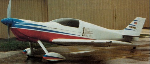
The American Affordable Aircraft Vision is an economical, 2 seat, all composite aircraft that is built from construction manuals. Designed by Steven Rahm for first time builders, each of the sub-assemblies cost less than $500.00 on the prototype. This plane was constructed by first time builders to test the construction manuals and no construction manuals were sold until testing of the prototype. The plane is all composite with no wood under-structure and uses no foams. There is a full sandwich skin on both sides. This is a plans built plane with supplemental parts. It can be built from manuals and raw materials or pre formed parts. The aim is to keep the wet-layup moldless airframe as low a cost as possible. Required power is 85-115 hp giving a cruise of over 150 mph. Engines up to 300 lb and 160 hp are acceptable. The prototype was first flown in 1996. Landing over 50 ft requires 1200 feet and takeoffs require 1500. Stall with flaps is 54 mph but touchdown can be slightly slower with ground effect. Climb rate solo with full fuel is 1400 fpm at sea level on 85 degree day with this prop and the economical Subaru engine. Two models are available – The sportier SP model and the extended wing EX version which is more suitable for high altitude flying, heavier loads, and lower experience pilots. Both versions are supplied with the plans. Construct entirely from the manuals using raw materials or from pre-formed parts. Most of the Visions are built with 44″ to 46″ wide cockpits. Even pilots as tall as 6’5″ can be accommodated. Weight should be at 850 lb empty, the prototype is close to 900. Intitally the gross weight has been set at 1350 lb. pending further testing and the aerobatic weight is at 1250 lb. (With SP wing, engines over 115 hp raise gross to 1450. With “EX” wing and engines to 120 hp gross is 1500 and for engines over 120 hp gross is 1600. +6/-4 g rating is always at 1250 lb.) When the Vision was designed in 1994 there was no thought of LSA. However, since each builder is the manufacturer of their own aircraft they also determine and set the gross weight. Setting the gross weight within LSA limits is simple enough as the Vision is well under any structural or performance concerns for an EX version. In order to fit the stall requirement with flaps up a full time leading edge slot would need to be installed; this is a simple matter once you understand just how easy it is to work with and modify composite structures. In the interest of having the most useful load it is critical that the empty weight is a low as possible since the gross weight can not be higher than 1320 lbs. The use of the carbon pre-built spar and Fold-a-Plane panels provided by Pro-Composites will greatly reduce the weight of the Vision – beyond what can be obtained through building according to the plans. Also important is using a light power plant such as the 120 hp Jabiru. Using these recommended changes a Vision should be in the 700’s empty weight. Keeping the top speed down is simply a prop choice so the whole equation of meeting LSA requirement is no major undertaking.
Staff at Electra Flyer (an Albuquerque-based hang glider company) sensed the presence of a growing demand for a powered, portable, super lightweight aircraft.
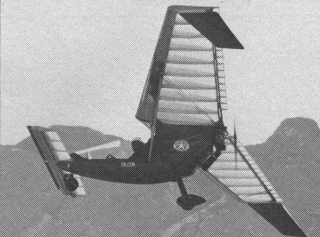
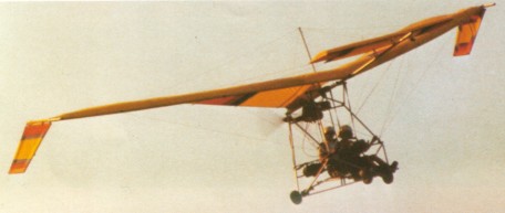
Subsequent development was intermittent encountering several obstacles. Although it flew well, it was not unlike other conventional powered hang gliders. Being heavier than desired, it failed to offer the portability necessary for convenience. While its performance fell within normal parameters, it lacked certain handling characteristics required for acceptance by the general flying community. It would be one thing to sell it to an experienced pilot, but another to sell it to a person with little or no flying background. They also wanted to produce a craft completely built and test-flown by the factory. Early in 1979, Romauld Drlik called to say that his research efforts had produced a craft so unique that Electra should halt their own ultralight development until hearing further from him. Romauld’s design was built around a power system, (as opposed to most ultralights which are hang gliders with engines added) and employed a canard wing. Conceived to be extremely portable, it could be carried on one’s shoulder, transported without special car racks and stored inside an apartment. And it could be built from available hang glider components. When the craft it had logged over 100 hours and undergone numerous changes, an agreement to manufacture the ship was made. Back in Albuquerque, the prototype was refined, employing a semidouble-surfaced airfoil and a flexible airframe which could be assembled/ disassembled in only 25 minutes.The result was EAGLE. In EAGLE, as the pilot’s body moves aft, the elevator automatically deploys in the “down” position, causing the nose to climb. Since the canard’s angle of incidence is higher than that of the main wing, it stalls first. Yet when this happens, it is in a relatively unloaded state. The resultant force is a slight oscillation or porpoising of the nose. Turning is accompanied by a steering wheel which controls drag rudders at the tips. The drag of the tip rudder causes the craft to turn, producing a coordinated roll. Pitch is controlled by fore and aft pilot movement which activites the elevator attached to the canard. While on the ground, the, foot controlled nosewheel is used for steering. At higher speeds, prior to takeoff and just after landing, the tip rudders can be used to steer. EAGLE folds up into a hang glider like package which can be carried on one’s shoulder (with the landing gear and engine over the other) and transported via car top. And the frame can be further disassembled to 12-foot lengths for airline transportation. Performance is a realistic 200-250 fpm climb at sea level (using the standard Chrysler engine), and over 400 fpm with the optional Chrysler Twin-pak engines.
The Eagle was never really a hang glider, being intended for motorized flight. It was foot-launched only once, as part of an early FAA requirement for ultralights, by one of the factory pilots.
Cruise speed is about 35 mph with the standard unit. Glide ratio is 10:1. Takeoff and landing speeds are 16-17 mph, and top speed is close to 50 mph. Mush speed is approximately 16 mph.
Canard ultralight Controlled by tip rudder for roll; elevator plus variable cg for pitch; twist grip throttle for climb and descent; steerable nose wheel. The 215B is a canard design with tip rudders, built and test flown before delivery. Elevator on canard responds to weight shift for pitch control. Steering handlebar moves tip rudders for roll con¬trol. Aluminum tubing, Dacron covering. POWERPLANT: Cuyuna two-cycle engine with in-flight restarter. LANDING GEAR: Trike, steerable nosewheel. Price 1982: $4,395 (with engine). Units delivered to June 1981: 1,016. The Eagle SL is a canard ultralight Controlled by tip rudder for roll; elevator plus variable canard for pitch; twist grip throttle for climb and descent; steerable nose wheel. Seat fixed. First year built: 1981. Price 1982: $4,695 (with engine). The prototype of the Eagle XL used a double skinned wing and retained the tiller of the previous models, but on the production models a side stick was substituted, controll¬ing the spoilers and the elevator hinged from the trailing edge of the canard. What was new also was the canard was fitted with fixed slats on the leading edge. The pushrod controlling the elevator has been replaced by a flexible control, similar to those fitted to outboard motors. The rudder bar works the tip rudders which were initially triangular as on the Eagle of 1981, but were redesigned in a trapezoidal shape and enlarged. The nosewheel steering is connected to the rudder bar. Appearing also in 1982 under the confusing title of Double Eagle, this single seat machine was renamed the Eagle 430B at the Sun’n’Fun fly in in March 1983 at Lakeland, Florida. It is designed for heavier pilots and has a pilot weight range of 200 300 lb (91 136 kg). It has been equipped from the start with the twin cylinder Cuyuna 430RR 35 hp engine, which makes it stand out from the ordinary Eagle, which has the 215RR 20hp engine. However, it retains the hybrid control of the latter: in pitch, the elevator responds to the pilot’s body movements, while the tip rudders respond to the tiller to control yaw. The frame of the Eagle 430B has been enlarged com¬pared with the basic model and the structure reinforced as a result. The Eagle 2 Place was a side by side two seat single engined high¬wing monoplane with conventional three axis control. Wing has swept back leading and trailing edges, and tapering chord; no tail, canard wing. Pitch control by elevator on canard; yaw control by tip rudders; roll control by one third span spoilers; control inputs through stick for pitch/roll and pedals for yaw. Wing braced from above by kingpost and cables, from below by cables; wing profile; double surface. Undercarriage has three wheels in tricycle formation; no suspension on nosewheel and suspension on main wheels. Nosewheel steering by lever between seats. Brake on nosewheel. Aluminium tube framework, without pod. Engine mounted below wing driving pusher propeller. The prototype two seat Eagle appeared in 1982, fitted with controls operating on all three axes, adopting spoilers as on the XL model but retaining the swing seat as used in the hybrid model 215B. It was originally equipped with the Cuyuna 430RR 35 hp, but this was dropped for the production machines in favour of the 50hp twin cylinder in line Rotax 503. This announcement was made in March 1983 in the course of the Sun’n’Fun Fly in at Lakeland, Florida where American Aerolights revealed full information on the Eagle 2 Place, which was classed as an experimental aircraft in the US. The aircraft was provided as a complete kit requiring 100hr for completion. The kit includes as standard the fairings for all three wheels, which are an option on the other Eagles, and also a nosewheel brake.
Double Eagle / Eagle 430B Engine: Cuyuna 430RR, 35 hp at 6000 rpm. Prop diameter x pitch: 54 x 36 inch, 1.37 x 0.91 m. Toothed belt reduction, ratio: 2.2/1. Max static thrust: 240 lb, 109kg. Power per unit area: 0.19hp/sq.ft,2.1 hp/sq.m. Fuel capacity: 5.0 US gal, 4.2 Imp gal, 18.9 litre. Length overall: 15.0 ft, 4.57 m. Height overall: 10.0ft, 3.04m. Wing span: 35ft, 10.67m. Mean chord: 4.3ft, 1.31m. Canard span: 7.8ft, 2.38m. Canard chord: 3.7 ft, 1.13 m. Total wing area: 180 sq.ft, 16.7sq.m. Main wing area: 151 sq.ft, 14.0sq.m. Canard area: 29 sq.ft, 2.7sq.m . Main wing aspect ratio: 8.1/1. Nosewheel diameter overall: 16 inch, 41 cm. Empty weight: 210 lb, 95kg. Main wheels diameter overall: 16 inch, 41 cm. Max take off weight: 520 lb, 236kg. Max wing loading: 2.88 lb/sq.ft, 14.1 kg/sq.m. Payload: 310 lb, 141kg. Max power loading: 14.9 lb/hp, 6.7kg/hp. Load factors: +8.0, 3.0 ultimate. Max level speed: 55 mph, 88 kph. Economic cruise: 37 mph, 60 kph. Stalling speed: 25 mph, 40 kph. Max ROC sea level: 750 ft/min, 3.8 m/s. Min sink rate: 400 ft/min, 2.0 m/s. Best glide ratio pwr off: 8/1. Take off distance: 100 ft, 30 m. Landing distance: 50 ft, 15 m. Service ceiling: 17,500 ft, 5340 m. Range ave cruise: 50 mile, 80 km. Pilot weight: 180-300 lbs.
Eagle SL Gross wt: 405 lbs. Empty wt: 180 lbs. Max pilot wt: 225 lbs. First year built; 1981.
Eagle XL Engine: Cuyuna 430RR, 35 hp at 6000 rpm. Prop diameter x pitch: 54 x 36 inch, 1.37 x 0.91 m. Toothed belt reduction, ratio: 2.2/1. Max static thrust: 240 lb, 109 kg. Power per unit area: 0.20hp/sq.ft, 2.13 hp/sq.m. Fuel capacity: 4.0 US gal, 3.3 Imp gal, 15.1 litre. Length overall: 15.0 ft, 4.57 m. Height overall: 9.0ft, 2.74m. Wing span: 35.0ft, 10.67m. Mean chord: 4.4ft, 1.35m. Canard span: 10.0 ft, 3.04 m. Canard chord: 2.2 ft, 0.67 m. Total wing area: 177 sq.ft, 16.5sq.m. Main wing area: 154 sq.ft, 14.4sq.m. Canard area: 22sq.ft, 2.0sq.m. Main wing aspect ratio: 8.0/1. Wheel track: 5.4ft, 1.62m. Wheelbase: 5.6 ft, 1.67m. Nosewheel diameter overall: 11 inch, 28 cm. Empty weight: 225 lb, 102kg. Main wheels diameter overall: 11 inch, 28 cm. Max take off weight: 464 lb, 211 kg. Max wing loading: 2.62 lb/sq.ft, 12.8 kg/sq.m. Payload: 239 lb, 109 kg. Max power loading: 13.2 lb/hp, 6.0kg/hp. Load factors: +8, 2.5 ultimate. Max level speed: 50 mph, 80 kph. Vne: 55 mph, 88kph. Economic cruising speed: 35 mph, 56 kph. Stalling speed: 26 mph, 41 kph. Max climb rate at sea level: 850 ft/min, 4.3 m/s. Min sink rate: 300 ft/min, 1.5m/s. Best glide ratio with power off: 7/1. Take off distance: 125ft, 40m. Landing dis¬tance: 125ft, 40m. Service ceiling: 17,500ft, 5340m. Range at average cruise: 50 mile, 80 km. Pilot weight range: 120-240 lbs.
Eagle 2 Place Engine: Rotax 503, 50 p at 6000 rpm. Propeller diameter and pitch: 58 x 27 inch, 1.47 x 0.69 m. Max static thrust: 285 lb, 129 kg. Power per unit area: 0.28hp/sq.ft, 3.0hp/sq.m. Length overall: 15.0 ft, 4.57 m. Height overall: 10.0ft, 3.05m. Wing span: 35.0ft, 10.67m. Mean chord: 5.0ft, 1.52m. Canard span: 10.0 ft, 3.05 m. Canard chord: 3.1 ft, 0.94 m. Total wing area: 177 sq.ft, 16.5sq.m. Main wing area: 146 sq.ft, 13.6sq.m. Canard area: 31 sq.ft, 2.9sq.m . Main wing aspect ratio: 8.4/1. Wheel track: 6.4ft, 1.93m. Wheelbase: 6.6 ft, 1.98 m. Nosewheel dia. Overall: 16 inch, 41 cm. Main wheels diameter overall: 16 inch, 41 cm. Empty weight: 310 lb, 141 kg. Max take off weight: 660 lb, 299 kg. Payload: 350 lb, 159 kg. Max wing loading: 3.72 lb/sq.ft, 18.2 kg/sq.m. Max level speed: 45 mph, 72 kph. Max power loading: 13.2 lb/hp, 5.9 kg/hp. Cruising speed: 42mph, 67kph. Stalling speed: 30mph, 48 kph. Max ROC sea level: 400 ft/min, 2.0 m/s. Min sink rate: 500 ft/min, 2.5 m/s. Best glide ratio pwr off: 4/1. Take off distance: 250 ft, 75 m. Landing distance: 250 ft, 75 m. Service ceiling: 8000 ft, 2440 m.
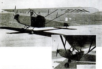
In 1930 American tested the American Eaglet at Kansas City. A home builders lightweight aircraft, it is a parasol type capable of carrying one person with a Cleone engine, or two with a Szekeley three cylinder 35 hp engine.
The conventional wings are built up in spruve and plywood. A feature of the fuselage is the way the lower longerons are brought together mid-way between the nose and tsil group as a single member. The fuselage is 23 inches wide and constructed of steel tubing as is the tail group.
Cables are used for control throughout. These run over pulleys and the aileron cables come down over two auxilliary pulleys at either side of the forward section of the cockpit. An aluminium seat is fitted with an instantaneous action safety belt.
The landing gear is a rigid inverted Vee type. It is equipped with 7×16 inch air wheels on four inch hubs. The landing gear is diagonally braced. A shoe tail skid is fitted, tied into the stern post and a rubber shock chord is used.
Wing tip ailerons are fitted. The horizontal stabiliser is ground adjustable and the fin is rigid. An unbalanced rudder is used.
Ordinary motor car gasoline and lubrication oil are mixed at 8:1 and carried in a single tank built into the cowling directly ahead of the pilot.
The gap where the wings are fasteed to the cabane section is covered with celluloid.
The Eaglet was sold for $995 with the Cleone engine and $1395 with the Szekeley in 1930.
Engine: Cleone Wingspan: 34 ft 4 in Length: 21 ft 6 in Height: 78 in Wing area: 164.4 sq. ft Max weight: 580 lb Engine weight: 46 lb Prop weight: 4 lb Battery weight: 15 lb Fuel capacity: 36 lb Speed: 60 mph Landing speed: 15 mph ROC: 350 fpm Glide ratio: 12-1 TO MAUW: 13 sec Fuel burn: less than 2 USG/hr
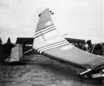
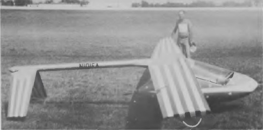
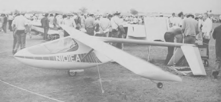
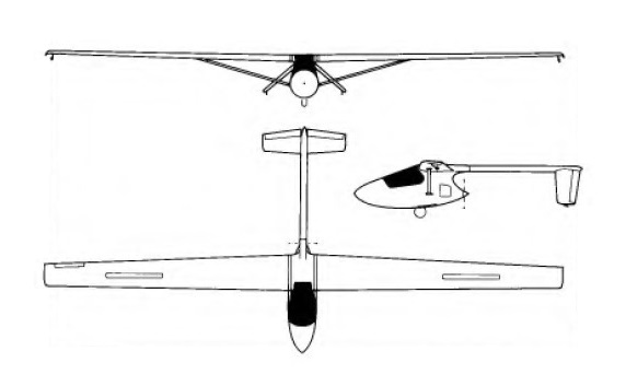
Designed by Larry Haig of Muskegon, Michigan, beginning in September 1974, the American Eaglet is a self-launching sailplane. The type is a high wing monoplane with a pod-and-boom type fuselage with the 12 hp(8.95kW) McCulloch 101B engine mounted aft of the cockpit and driving a 2 ft (60.96 cm)-diameter pusher propeller. The nylon propeller blades fold aft automatically when the engine stops. The cantilever inverted-Vee tailplane and elevators are carried on a tail boom that is a thin-walled 5 in (12.7 cm)-diameter aluminium tube with a moulded glassfibre tailcone. The compact cockpit includes a side-mounted control stick and aft-hinged, single-curved canopy. Construction is largely of glassfibre and urethane foam cores, with some components of aluminium.
The wings are stressed skin structures with spruce load-bearing spars and a single aluminium tube bracing strut on each side; the spars are surrounded by a urethane foam core, the leading edges and wing tips being of moulded glassfibre, and the urethane core portions are covered with epoxy-bonded precure glassfibre skin. There are no ailerons or flaps, but the functions of these two (ie roll and glide path control) are combined in two spoiler-like surfaces called ‘spoilerons’ at 30% chord on each upper surface towards the wing tip. The forward portion of the fuselage consists of two pre-formed glassfibre half shells pop-riveted to tubular aluminium longerons, the main load-bearing member in the fuselage being the bulkhead which carries the pilot’s seat on one side and the engine mounting on the other. This also carries the tail boom at the top rear, the monowheel at the bottom and the wing spar carry-through at the top, and this bulkhead is an aluminium-skinned urethane foam composite structure. There is a combined pitot tube/lifting handle in the fuselage nose. The inverted-Vee tailplane is very similar to the wings structurally, with an epoxy/glassfibre skin over urethane foam cores, and this V-tail greatly improves control in pitch and yaw, as the prop wash ‘blows’ directly over the tail surfaces; the V-tail also makes spins impossible. The manually-retractable monowheel has an external friction-pad brake, and is supplemented by a tailwheel under the tip of each tailplane.
The American Eaglet can be completed and flown as a pure sailplane, without the engine; the powerplant fitted is a McCulloch 101B single cylinder two-stroke engine developing 12.2hp at 8,000rpm, and drives a two-blade fixed-pitch pusher propeller with nylon plastic blades that fold backwards through 90° when the engine is stopped. The engine is intended only for take-off and self recovery, and is not designed for continuous cross country operation; it can be restarted in flight. A fuel tank of 2 litres (0.5 US gallons) capacity is provided. Fuel tank capacity is generally sufficient for one takeoff and climb to 2,000 feet AGL and three airborne restarts and climbs from 500 feet back up to 2,000 feet. The McCulloch 101B engine was available in only limited quantities, and the West Bend 820 engine will be fitted when availability of the 101B becomes a problem.
The Eaglet was designed for kit building and Larry Haig formed the AmEAGLE Corporation to market it.
Construction of the prototype, registered N101EA, started in June 1975 and this made its first flight on 19 November that year; a second prototype was later flown. A total of 400 kits had been ordered by early 1980, of which 20 had been completed.
Engine: McCulloch 10IB, 8.95 kW / 12 hp Wing span: 36 ft 0 in /10.97 m Length: 16 ft 0 in / 4.88 m Height: 0.91 m / 3 ft 0 in Wing area: 72 sq.ft / 6.69 sq.m Empty Weight: 160 lb / 72.5 kg Payload: 200 lb / 90.5 kg Gross Weight: 360 lb /163 kg Water ballast: None Fuel capacity 2 lt / 0.5 US gal Wing Load: 5 lb/sq.ft / 41.04 kg/sq.m Max speed: 115 mph / 100 kt / 185 km/h (in smooth air, power off) Aspect ratio: 18 Airfoil: Wortmann FX-61-184 Stall speed: 33 kt / 61 km/h MinSink: 0.76 m/s / 2.50 fps / 1.48 kt at 40 mph / 35 kt / 65 km/h L/DMax: 27 @ 84 kph/ 45 kt /52 mph Max rate of climb at sea level: 400 ft/min / 122 m/min Take-off run: 1,000 ft No. of Seats: 1
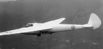
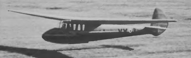
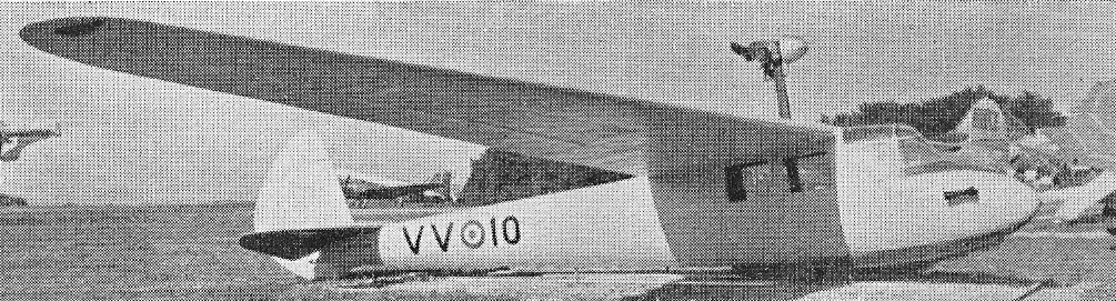
Originally, The Kangaroo is a wooden glider, two-seater, high-wing, and about 20m wingspan. It was designed in 1939 by the Gliding Institute Polytechnic of Milan (Centro Volo a Vela del Politecnico Di Milano) under the direction of the Engineer Ermenegildo Preti. In addition to the prototype, the Italian air force has ordered 32 copies. The first flew in 1940, only two copies will be built during the duration of the war. Others, built in 2 lots by two different companies were produced between 1953 and 1955. It was at this time, a significant number of aircraft.
The “Palas” version corresponds to a transformation seater glider with a Turbomeca Palas jet engine.
The jet version was created by Adrianno Mantelli, from one that had crashed. It was rebuilt with a shortened wing, and with the addition of a Turbomeca Palas engine of 150kg thrust. This came from the prototype Caproni Trento F-5 jet. The air inlet is a removable scoop on the top of the fuselage.
In this configuration, Adrianno broke the world record for altitude jet less than 800 kg, with a flight to 9366 m, 24 September 1964.
A high-wing cantilever monoplane built completely in wood, the CVV6 had a fixed, single wheel undercarriage.
Wingspan: 19.20 m (63 ft 3 in) Length: 8.00 m (26 ft 2 in) Wing area: 21.60 m² (235.5 sq.ft) Empty weight: 280 kg (616 lb) Payload: 180 kg (396 lb) MTOW: 460 kg (1012 lb)
The Canguru was designed in 1939 by the Gliding Institute Polytechnic of Milan (Centro Volo a Vela del Politecnico Di Milano) under the direction of the Engineer Ermenegildo Preti.
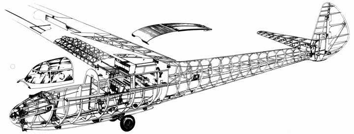
The Canguru two-seater is of conventional all-wood and fabric construction, with a high cantilever wing which has a single main spar with a torsionally stiff D-type leading edge; the wing is in two halves and can easily be detached for transport. CVV-type air brakes limit the maximum diving speed to 137mph. The oval-section fuselage is a monocoque structure and the two pilots are seated in tandem, an unusual feature being the location of the second pilot actually beneath the wing rather than ahead of it or in line with the leading edge. The cantilever tail unit has a low-set tailplane.
The CVV 6 Canguru two-seater was developed by the CVV (Centre Volo a Vela del Politecnico di Milano) and built in small numbers by Ambrosini – or Societa Aeronautica Italiana, Ing A. Ambrosini & C. It was also built under licence by Meteor SpA, Costruzioni Aeronautiche.
In addition to the prototype, the Italian air force has ordered 32 copies. The first flew in 1940, only two copies were built during the duration of the war. Others were produced between 1953 and 1955.
A powered prototype Ambrosini CVV6 Canguro, with Italian military number MM100028, was built with a 20 hp flat-twin engine.