At Exeter Airport, during 1948-1950, a series of four-seat lightplanes were constructed: Series 1 CH.3 Ace, Series 2 CH.3 Super Ace, and Series 4 CH.3 Skyjeep. The first of these high-wing cabin monoplanes was flown in August 1946, but high operating costs and unacceptable control system affected sales of the Ace and Super Ace.
The prototype CH.3 Series 1, was fitted with a 125 hp Lycoming engine, a single fin and rudder, and a wooden wing.
Production versions, the CH.3 Series II, was all-metal and fitted with a 145 hp DH Gipsy Major 10 engine. It also has the twin fin and rudder assembly later fitted to the prototype.
The CH.3 Series III had a tailwheel landing gear.
The Series IV version of the Series III had a hinged rear fuselage deck.
By August 1959 the tail wheel undercarriage CH.3 Srs. 4 Skyjeep VH-RCD four-seater had a deepened rear fuselage.
Engine: 1 x Gypsy Major Mk.10, 145 hp Wingspan: 36 ft Length: 21 ft 6 in Empty weight: 1344 lb Loaded weight: 2350 lb Max speed: 126 mph Cruise: 110 mph Stall: 38 mph Range: 400 mi Seats: 4
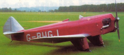
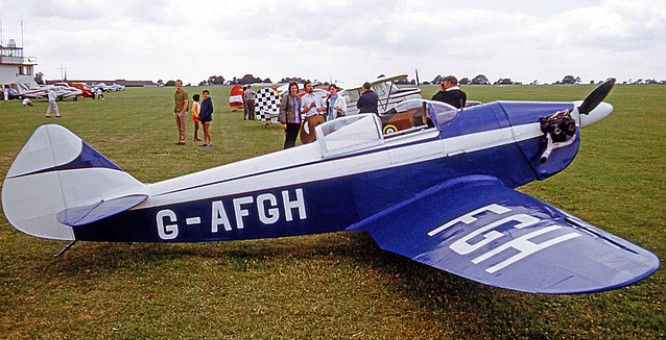
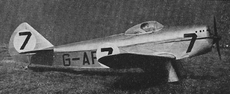
A single-seat light aircraft designed by Hon Andrew W. H. Dalrymple and A. R. Ward. A low wing open-cockpit wooden monoplane with fixed “trousered” landing gear and Carden-Ford engine, first flown April 1937.
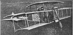
A design of Fred T. Childs of Akron, Ohio. The top wing measured 36 by 7 ft, and the lower 26 by 7 ft, the surface being 578 ft. It had two side surfaces measuring 6 by 7 ft ft, set at a dihedral angle, the idea being that these will maintain equilibrium during flight on the theory that a tip to one side or the other will cause an increased resistance on the side tipping over, with a resultant righting of the machine. The total weight of the machine, without the engine, was given as 250 lbs.
For exhibiting the machine at a county fair, a 2-cylinder, 7 hp Waterman engine was installed, but the motor intended to drive the machine was a 35 hp air-cooled, promised not to weigh more than 150 lbs including the magneto and accessories. The two 7-foot propellers were driven by cable, but it was intended to try chains and sprockets.
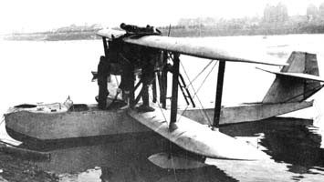
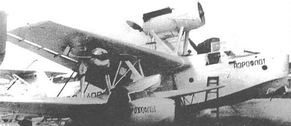
The Grigorovich MR-5 flying boat was built at Factory No.22 and in the summer of 1929 it was sent to Taganrog for testing. During its development it was found that the hull behaved correctly in the water, but during takeoff operations a large curtain of water formed in front of the plane, which made the process difficult. The take-off run distance was also getting too long. The commission that studied the possible destiny of the model concluded on December 1, 1929, that the problems were due to a bad design of the bow section of the hull.
Grigorovich had been arrested, so trying to save the model, the development was transferred at the beginning of 1930 to the construction bureau OPO-4, directed by the Frenchman Paul Aimé Richard . The development was included in the KB ‘s work plan for the year, but very little attention was paid there to improving one design created by another, so finally, at the time of Richard ‘s departure from the USSR , the MR-5 had received no attention.
The need for reconnaissance flying boats was great so in 1931 the MR-5 was delivered to the new TsKB of Factory No.39, where the head of the naval department IV Chetverikov was in charge of the modifications to achieve better behavior in the water.
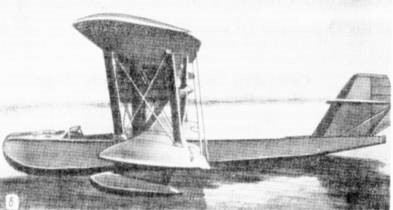
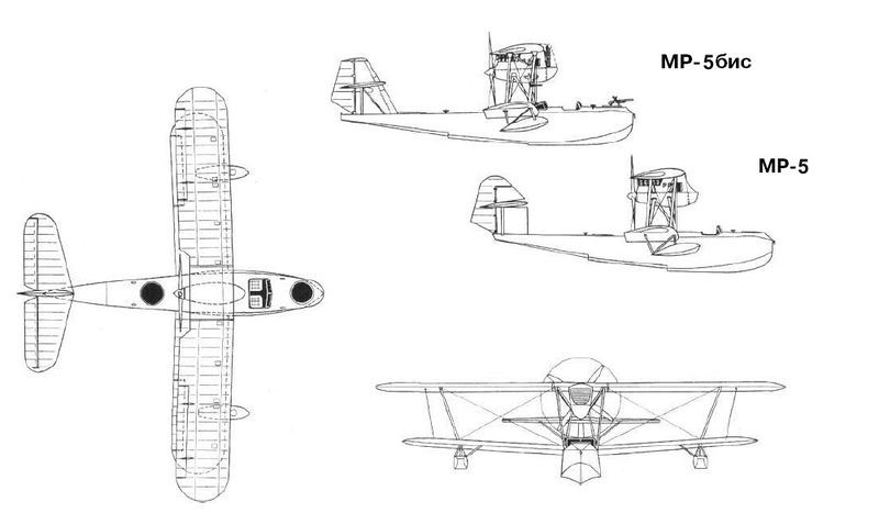
For this purpose Chetverikov decided to build a new wooden hull with better lines and the empennage underwent modifications, increasing its area. The new model was numbered 10 within the TsKB designations, but was generally known as the Chetverikov MR-5bis (Russian: Четвериков МР-5бис/ЦКБ-10).
In January 1932 Chetverikov read a report that the tests of the TsKB-10 had started, but at that time it referred only to the tests on skis. The complete cycle of tests was completed by the summer of 1932, being developed in the section of the Moscow River where the Gorky Central Park of Culture and Rest (TsPKO) is located today.
In these tests, the hull behaved positively, noting a noticeable decrease in splashes. Despite this, the long-awaited serial production was not approved. The Italian Savoia S-62 flying boat, which had entered service with the VVS RKKA under the designation MR-4, was successfully produced in the Taganrog workshops. Only the on MR-5bis was built.
The MR-5bis differed fundamentally from the original model in its new hull
In some sources Grigorovich ‘s original model has been named as MR-3 and Chetverikov’s version as MR-3bis. This presumably constitutes an error, which has become widespread on multiple sites on the internet that reference these sources. The searches carried out by the Soviet researcher M. Maslov in the original documents of the time show that the term MR-3 was used only to designate the reconnaissance flying boat ROM-1 and MR-3bis designated the improved version ROM-2.
Type: MR-5bis Powerplant: 1 x 680/500 hp M-17 Wingspan: 15.60m Wing area: 53.00 m² Length: 11.40m Empty weight: 2050kg Maximum takeoff weight: 3100 kg Wing loading: 59.0 kg/m² Power Load: 6.2kg/hp Fuel + oil load: 440+30 kg Full load capacity: 1050kg Top speed: 190km/h Cruising speed: 162km/h Landing speed: 85km/h Practical range: 720 km Endurance: 4 hours Practical ceiling: 4000 m Landing Time: 22s Take off time: 35s Accommodation: 2
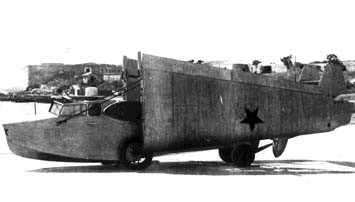
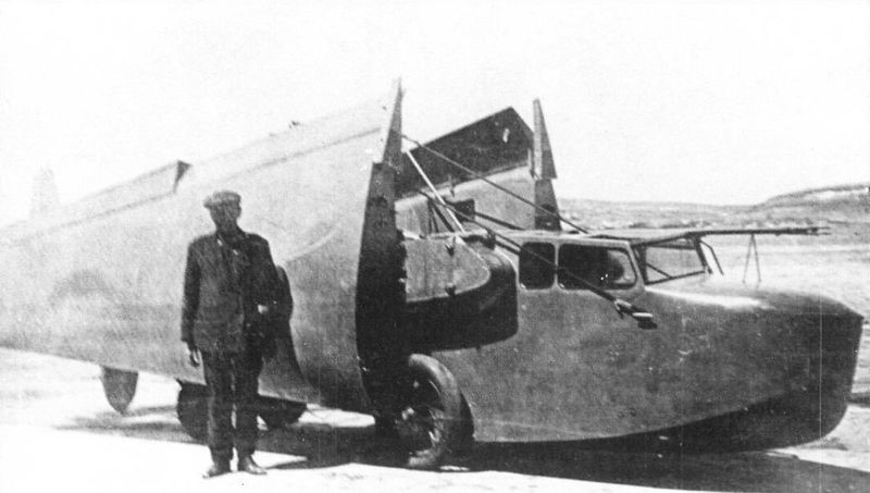
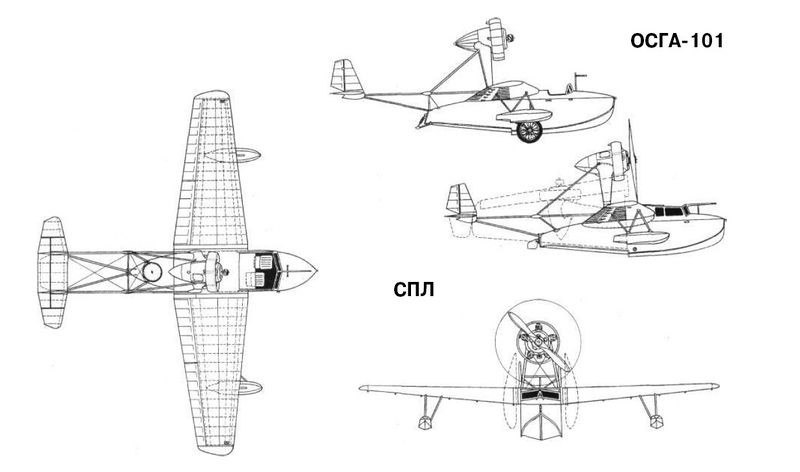
The development of an aircraft to carry out operations from submarines was taken over by IV Chetverikov in 1931. In its design, Chetverikov decided to start from the already proven design used in the OSGA-101 light flying boat. The new model was known as SPL (Russian: Четвериков СПЛ), after the acronym for Samoliet Podvodnoy Lodki or Airplane for submarines.
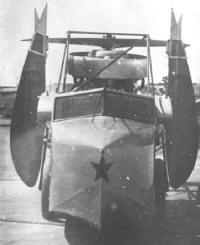
As fundamental differences, the general dimensions were reduced in order to allow the aircraft to be accommodated in a sealed hangar of only 2.5 x 7.5 meters. Systems were also developed that would allow the wing, the power plant and the stabilizer consoles to be transformed, using quick-action fixing screws instead.
The decision to build a flying boat of minimum dimensions also had its cost. The tail had very little area, so the flying boat had little stability. The visibility of the cabin was poor, especially for the observer, since the crew was forced to position themselves towards the center of gravity of the aircraft in order to reduce the length. To reduce the weight, the flying boat did not have the possibility of carrying any type of armament. The resulting aircraft looked more like a sports competition model than a military aircraft.
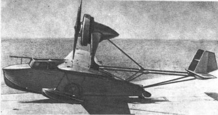
The SPL was designed as a high-wing monoplane flying boat. The wing, similar to that used on the OSGA-101, featured a three-spar configuration with a trunk frame and wooden construction. The areas on the outside of the wings between the leading edge and the intermediate spar were covered with plywood. The rest of the wing presented fabric covering, sewn with thread to the ribs.
Unlike the OSGA-101, on the SPL there were no fasteners on the first and third stringers. In this way the force of the support was exerted only on the central beam. In the extended position, the wing was secured by a quick-release fastener located at the top of the center spar. At the bottom was a gimbal that was inserted into a cavity in the centroplane. To pick up the wing, it was enough to release the fixator, rotate the wing console around the axis of the spar and move them towards the sides of the hull.
The SPL wing was designed using the MOS-27 airfoil with a relative thickness of 18% at the root section and 12% at the tips. This fact, together with a considerable narrowing of the wing, made it possible to obtain a break in the flow at the wing tips when operating with large angles of incidence. For this reason, it was enough for the pilot to pull the stick a little hard on landing so that the plane began to dive on the wing. At that time, the phenomenon of wingtip vortices was little studied, so the fault for this behavior was attributed to the poor transverse stability of the model. Attempts were made to cure this problem by increasing the wing’s wing gradient to about 5°, but the effect was nil. According to Chetverikov himself the problem could be compensated thanks to the great effectiveness of the ailerons.
The large-area wings occupied the entire trailing edge of the consoles and featured two sections: an inner or root section and an outer section. The inner sections could be used as flaps during landing. The wings were made of wood and featured fabric-covered box-type spars. The leading edge was covered with plywood.
The underwing floats had a wooden structure with frames and braces, covered with plywood. In the SPL, unlike the OSGA-101, the construction of these floats was simplified.
The hull of the SPL was similar to that of the OSGA-101 and featured all-wood construction. The structure had several frames with stringers and braces and plywood sheathing. The hull design demonstrated excellent hydrodynamic qualities, which was necessary for the operation of the model in the open sea. The large angle of the keel reduced the overloads when riding the waves and the high rails ensured a smooth takeoff and landing in tidal conditions.
The three-sided tail beam was made of steel tubes and its rigidity was ensured by means of cable-stayed straps. The control cables for the rudders were routed inside the tubes of the structure. The empennage was built on a fabric-covered welded steel tube structure. The keel spars and stabilizers as well as the ribs and leading edges were constructed from thin steel tubing. Unlike the OSGA-101, in the SPL the stabilizers had a biplane structure in order to reduce their wingspan.
The SPL lacked its own landing gear and for operations on land, removable wheels were used whose axles were fixed to a tube that passed through the hull from side to side.
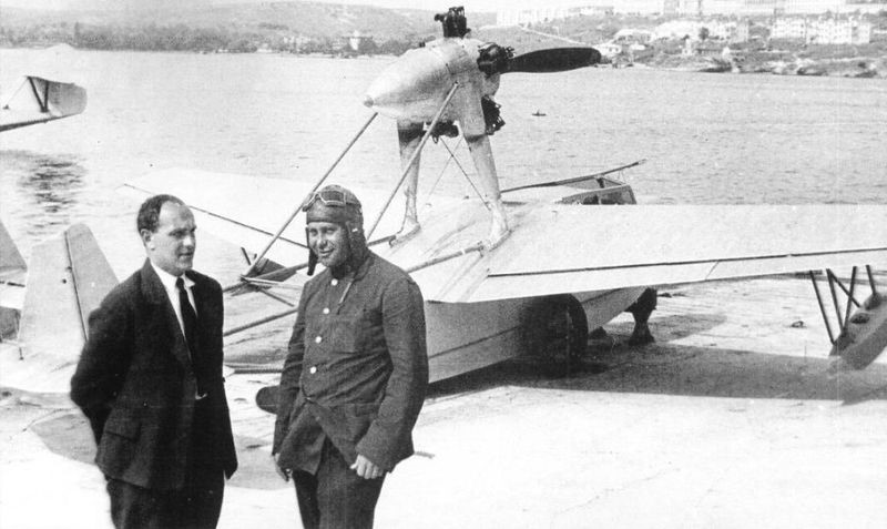
The power plant selected was the excellent 100 hp M-11 driving a two-bladed, fixed-pitch wooden propeller. This propeller had a diameter of 2.3 meters. Originally, an annular Townend-type hood made of aluminum was installed, but it was soon found that the aerodynamic improvements of its use on the M-11 engine they were not considerable, reason why it was eliminated. The engine was located on a high pile conceived of welded steel tubes and designed to prevent water splashing on the propeller during takeoff and landing operations. To facilitate its packing inside the narrow container, the engine lay down backwards. To achieve this in the SPL the drive location was slightly rearward, the strut could pivot and the rear mount base was moved rearward by the main tail tube. The motor control was carried out by sheathed cables that were collected along with it.
The optimum position on takeoff and landing ensured a wing angle of incidence of 6º, but during flight the optimum angle was 2º. For this reason, in flight, the nose of the flying boat was inclined slightly downwards, while the engine was at that moment totally in line with the flow of navigation.
In the motor gondola there was a 10-liter tank for oil and another 20-liter tank for fuel. The main fuel tanks were located in the hull.
The dimensions of the SPL once folded were only 7.45×2.12×2.35 meters. Flight readiness was achieved in 4-5 minutes and after the mission the wings, tail and engine could be folded in 3-4 minutes.
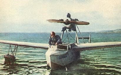
The SPL was fully painted silver. Originally it had no markings or symbols, but later on its nose and wings, above and below, the characteristic red stars were painted. The Gidro-1 example, which was shown at the Milan fair, featured Aeroflot symbols in blue on both gunwale and lacked the red stars.
The SPL was built in the workshops of the Sled and Hovercraft Building Department (OSGA), subordinate to the NII GVF. The prototype was finished by December 1934 and moved to Sebastopol to carry out sea trials, which were completed on August 29, 1935. Its realization was in charge of the test pilot of Factory No.45 AV Krzhizhevski.
Designer Chetverikov and test pilot KrZhizhevski during SPL tests at Sevastopol Factory No.45.
The tests demonstrated the feasibility of the packing and unpacking operation of the aircraft in the submarine in a time of 4-5 minutes, its possible take-off and its effective recovery after the flight. The authors of the project managed to obtain a container only 7.45 meters long and with a diameter of 2.5 meters. In general, the SPL showed acceptable performance in the water, but its seaworthy conditions were not good, especially in the open sea. It was clear that very little more could be asked for an aircraft of this type, but in these conditions the aircraft was not very attractive to the military.
The Gidro-1 next to an MP-1bis with the colors of Aeroflot to participate in the fair in Milan in 1936.
In 1936 the SPL with the Aeroflot symbols and Gridro-1 denomination, participated in the Milan Fair, receiving a positive evaluation.
Gidro-1 tests on water.
On September 21, 1937, in this plane, the pilot AV KrZhizhevski established a world speed record of 100 km, reaching 170.2 km/h, and on October 7 of that year, he established a new distance record for aircraft of its category. when reaching 480 km and high when setting 5400 meters. Despite these results, the model did not have further development.
Documentary references to a flying boat built by Chetverikov have been found at Sevastopol Factory No.45. It could be a second issue of the SPL, but this is just conjecture.
SPL Power plant: М-11, 100 hp Wingspan: 9.6m Wing area: 13.4 m² Length: 7.4m Height: 2.72m Empty weight: 592kg Weight with normal load. 800kg Maximum takeoff weight: 879kg Fuel weight: 60kg Oil weight: 10kg Total load capacity: 208 kg Wing loading: 59.7 kg/m² Overloaded wing loading: 65.7 kg/m² Power load: 8kg/hp Overloaded power load: 8.8 kg/hp Maximum speed at sea level: 186 km/h Cruising speed: 174km/h Landing speed: 85km/h Endurance: 2 hours Range: 480km Practical ceiling: 5400 m Time to 1000m: 3.9min Time to 2000m: 8.7min Time to 3000m: 15.3min Time to 4000m: 25.5min Time to 5000m: 50.0min Accommodation: 2
Chetverikov SPL and OSGA-101 three views, showing main differences
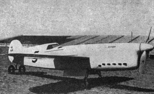
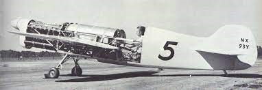
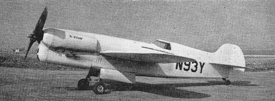
Art Chester followed on his successful air racer the “Jeep”” with the Goon. “Goon”, like “Jeep” was named after characters in Popeye cartoons and comic strips.
The Goon was built with a conventional welded steel tube frame and fabric covering. The wings used spruce spars and plywood covering. The mid-wing taildragger aircraft featured short-legged retractable landing gear. The engine was prepared to turn clockwise (as normal for some British inlines of the era) in anticipation of mounting a custom French propeller, but the propeller was also customized for American engines, and the engine needed to be modified again to rotate normally.
The Chester Goon aka The Chester Special #2 was built for the 1938 National Air Races.
Placed second in the Greve Trophy Races of the 1938 National Air Races with a speed of 250.42 mph (403 km/h). 1938 Thompson Trophy – Has to drop out after failure of prop. 1939 National Air Races – First place at 263.39 mph (424 km/h), winning $9000. 1939 Thompson Trophy – Dropped out with engine trouble.
In 1939 20th Century Fox featured the Goon in the movie series Tailspin Tommy. By 1956, the Goon was purchased in unflyable condition. During the 1956 rebuild, a 190 hp Lycoming O-435-1 engine was installed in place of the Menasco, including a cut down Beech-Roby propeller and wheel brakes.
Lycoming powered
On December 23, 1957, the rebuilt Goon was test flown by Harvey Mace at Sacramento, California.
The Goon was purchased in 1991 by the Crawford Auto-Aviation Museum and was awaiting restoration in Macedonia, Ohio.
Powerplant: 1 × Menasco C-6-S Buccaneer, 450 hp (340 kW) Propeller: 2-bladed French Ratier Controllable Wingspan: 18 ft 6 in (5.64 m) Length: 20 ft 6 in (6.25 m) Crew: One
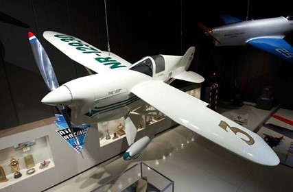
Arthur Chester designed and built the Chester Special in his garage in the early 1930s. The racer was completed in 1932, but was not fully tested by the time of the 1932 National Air Races.
The Special N12930, later called the “Jeep,” was tested on August 14, 1932. Flight tests proved the aircraft was unsatisfactory for competition and major changes were made before entry in the 1933 races. The 1932 version had a semi-open cockpit with a rather flat windscreen. The airframe was stripped for extensive modifications, including shortening the wings by two feet and chopping the length by 23 inches. The bay behind the cockpit was eliminated and 18 pounds of lead were required to correct the balance. A hatch was installed over the cockpit and the cowling was changed.
The fuselage was constructed of welded steel tubing with plywood fairing aft of the cockpit and covered in fabric. The wings were made of birch spars and plywood ribs with spruce cap strips. The leading edges were plywood covered and the rest of the wing was covered with fabric. The Chester Special was powered by a 185 hp Menasco C4S engine.
Art first competed with his Special in the 1933 National Air Races, where he won one first and four fourths, with his best speed reaching 155 miles per hour. At the 1936 National Air Races the Chester Special appeared under the new name “Jeep,” taken from a character in the famous Popeye comic strip. Chester raced his Special until 1937, reaching an overall best speed of 235 miles per hour and always taking home at least a little prize money.
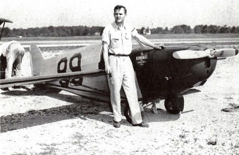
The Jeep was later sold to Tom Stauch, who intended to fly it at the 1939 National Air Races, but failed to file the paperwork on time. The Special didn’t reappear until 1947 when it participated in the Goodyear Races after a complete rebuild. The engine was switched to an 85 hp engine and the airplane was so revamped that it could hardly be called a Chester racer, only the license number and tail section remained unchanged.
William T. Flack – 1947 Goodyear
Bill Flack of Warwick, New York, rebuilt the ‘Jeep’ for the 1947 Goodyear races and was the winner of the consolation race.
Art Kilps acquired the Jeep, which he donated to the EAA AirVenture Museum in 1977. Before the racer was put on display, EAA Member Henry Proescher took on the project of restoring the Chester Special to its 1936-37 racing configuration. The restoration took over six years to complete, after which, the historically accurate racer was put on display in the AirVenture Museum.
Engine: 185 hp Menasco C4S Wing Span: 16 ft. 8 in. Length: 15 ft. 1 in. Height: 4 ft. 10 in. Wing Area: 48 sq. ft. Empty Weight: 765 lbs. Gross Weight: 1150 lbs. Fuel Capacity: 30 USgal. Maximum Speed: 255 mph Cruise Speed: 219 mph Range: 325 mi.
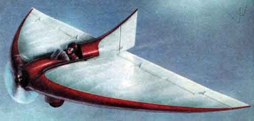
Shortly after the completion of the BICh-2, BI Cheranovski began developing a powered version that would receive the designation BICh-3(Russian: Черановский БИЧ-3).
The BICh-3 was basically a BICh-2 with the central axis installation of a Blackburn Tomtit engine of only 18 hp. Like its predecessor, it was conceived entirely of wood, with a textile coating, being quite light.
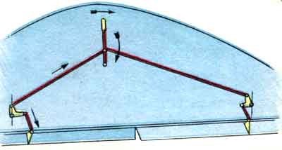
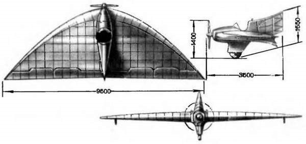
Characteristic of Cheranovski designs , the BICh-3 featured a thick wing with a parabolic leading edge and a slim straight trailing edge with control surfaces along the entire span. These surfaces, made up of ailerons and elevons, were capable of guaranteeing control of the aircraft’s flight.
Detail of the flight control system on the Cheranovski BICh-3.
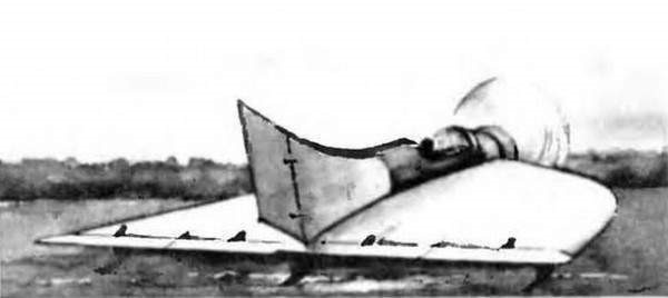
The pilot was located in a cockpit located behind the power plant, practically hidden within the thick wing profile. The open cockpit was protected by a windshield and ended in a fairing that smoothly ended at the rudder. This rudder, blown by propeller flow, was highly effective.
In the lower center of the plane a wheel was fixed, which guaranteed the necessary angle of attack to allow takeoff.
The BICh-3 was successfully tested at the end of January 1926. Several flights performed by BN Kudrin showed that the aircraft was not very stable, but was easy to control in the air. The longest flight was made on February 3 and lasted 8 minutes.
The scheme had proven its worth. The BICh-3 went down in history as the first engine-powered flying wing to fly successfully. Its design would be continued in the Cheranovski BICh-7 of 1929 and in the successful BICh-7A of 1932, with a more powerful powertrain.
BICh-3 Engine: Blackburn Tomtit, 18 hp Wingspan: 9.50 m Wing area: 20 m² Length: 3.50 m Empty weight: 140 kg Takeoff weight: 230 kg Fuel capacity: 10 kg Payload capacity: 90 kg Wing loading: 11.5 kg / m² Power load: 12.8kg / hp Maximum speed: about 100 km / h Landing speed: 40 km / h Accommodation: 1