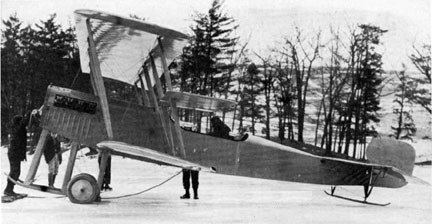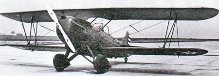
Curtiss 37 / L-113 Falcon / 46 / O-11 / O-39 /A-3 Falcon / XBT-4 Falcon / 38 / O-1G Falcon

The US Army Air Service staged two competitions, in late 1924 and early 1925, to find successors to the DH 4 series of observation and light bomber aircraft.
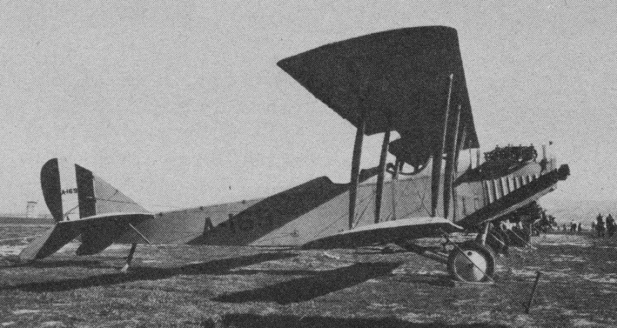
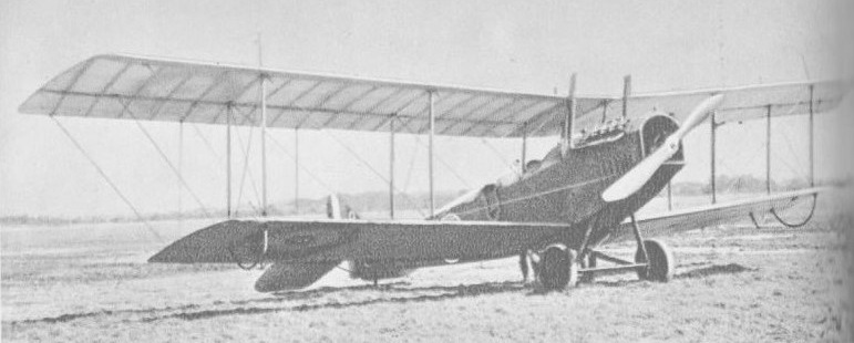
The first Curtiss biplane to bear the name Falcon was the Liberty-powered Curtiss L-113 (Model 37). It was unsuccessful when evaluated in 1924 as the XO-1 in competition with the Douglas XO-2 but was accepted for production the following year when re-engined with a 380kW Packard 1A-1500. It was a conventional unequal-span biplane with a wing of wooden construction that incorporated sweep-back on the outer panels of the upper wing. The fuselage was built up from aluminium tubing with steel tie-rod bracing, and the tail unit included a balanced rudder; the fixed divided landing gear was of tailskid type.
The Packard engine proved a failure, and the 102 production O 1s were fitted instead with various models of the 435 hp Curtiss D 12 (V¬1150) engine.
The new biplane went into production as the O-1 (Model 37A) for observation duties with the US Army. The initial order was for 10 aircraft re-engined with a Curtiss D-12. One of these was completed later as the O-1A with a Liberty engine, and the first O-1 was converted to O-1 Special configuration as a VIP transport.
Forty-five examples of the O-1B (Model 37B) were ordered in 1927, this first major production version incorporating such refinements as wheel brakes and an underbelly auxiliary fuel tank which could be jettisoned in flight. They were followed by four O-1C aircraft, part of the O-1B order, converted to serve as VIP transports by enlargement of the rear cockpit and the addition of a baggage compartment. (The designation O-1D was not used).

In 1929 the US Army ordered 41 of the O-1E (Model 37I) with V-1150E engines developed from the original Curtiss D-12. A number of other improvements included the introduction of oleo-pneumatic shock-absorbers, Freise ailerons, and horn balanced elevators. One O-1E was modified subsequently as a VIP transport becoming redesignated O-1F (Model 37J). The XO-1G (Model 38) replacing the twin Lewis guns on a Scarff mounting that equipped the earlier models by a single gun on a post mounting. Other modifications introduced redesigned horizontal tail surfaces and a steerable tailwheel.

The XO-1G was originally an O-1E which had been modified previously to contend as a new US Army basic trainer under the designation XBT-4 (Model 46).
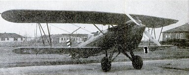
XBT-4

The XBT-4 of 1930 was produced at the Curtiss-Wright experimental facility in Garden City in 14 days. For its training role, the rear cockpit is higher than previous models, and the squared cowling is sloped to give good visibility. A full thickness sponge rubber pad is mounted over the instrument panel with cutouts for the dials. The seats may be raised or lowered 7.5 in, and are tilted back at 13˚ from level. All cockpit mechanism is hidden behind wooden veneer walls.

Successful tests led to construction of 30 series examples of the O-1G with improved strearnlining, slightly smaller wings, and redesigned rear cockpits, were 16 km/h (10 mph) faster than the O 1B, bringing total O-1 production for the US Army to 127.

Two O 1 conversions (to O 1A and XO 11) to a 420 hp Liberty engine, 66 Liberty engined models were produced for the US Army.

The O-1 Falcon and its variants saw a decade of service with the observation squadrons of the US Army Air Corps and ended their days with reserve National Guard units. The basic design was adapted also as the A-3 attack biplane which saw considerable use. The A 3, based on the O 1B was an attack version of the Falcon. It had two additional 0.30 in (7.62 mm) machine guns in the lower wings and could carry up to 91 kg (200 lb) of underwing bombs. The standard armament for most Falcons was four 0.30 in (7.62 mm) guns, two in the wings and a twin mount on a Scarff ring in the rear cockpit.
There were also export versions and a number of commercial Falcons.
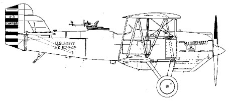
A-3

Several experimental Falcons flew with 600 hp Curtiss V 1570 Conqueror engines. They included the XO 13 and XO 13A (two converted O 1s) for the 1927 national air races; one O 13B; three YO 13Cs, otherwise similar to the O 1E; one YO 13D (super¬charged Conqueror); one XO 16, a Con¬queror engined O 11 with Prestone (ethylene glycol) cooling; and one Y10 26, similar to the O 1E but with a GIV 1570A geared Con¬queror and modified cooling system. How¬ever, the only Conqueror powered production version, was the O 39, with Prestone cooling and a smaller rudder, but otherwise similar to the O 1G. Ten of these were built in 1932. Other one off engine testbeds included the XQ 12 (Pratt & Whitney Wasp), con¬verted from an O 11, and XO 18 (Curtiss Chieftain). Other conversions, not involving an engine change, were four O 1Bs to O 1C unarmed VIP transports; one O 1E to an unarmed O 1F; another O 1E to XBT 4 basic trainer configuration, this later becoming the prototype for the O 1G; and one O 11 to O-¬11A (incorpora~ the improvements of the O 1E).
Except for the O 1C and O 1F, standard armament on the observation Falcons was four 0.30 in (7.62 mm) machine guns: two fixed, forward firing guns in the nose and two on a Scarff ring in the rear cockpit. Between 1927 30, Curtiss also produced 154 attack versions (76 A 3s, based on the O 1B, and 78 A 3Bs, based on the O 1E). These had two additional 0.30 in (7.62 mm) guns in the lower wings and could carry up to 91 kg (200 lb) of underwing bombs. There was also, in 1928, one XA 4, equivalent to the A 3, but with a 421 hp R 1340 1 Wasp engine.
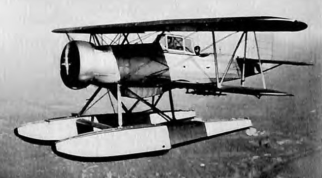
Wright Cyclone powered Falcon

Variants

U.S. Army Air Corps

A-3
Model 44, attack aircraft version of O-1B, armed with two 0.30 in (7.62 mm) machine guns and 200 lb (91 kg) of bombs; 66 built for the USAAC.
A-3A
Six A-3s converted into trainers.
A-3B
Model 37H, attack version of O-1E, with six machine guns, including two mounted in wings; 78 built.

Curtiss XA-4 Falcon

XA-4
One A-3 with a Pratt & Whitney R-1340-1 Wasp radial piston engine. Scrapped in March 1932, but the design was the basis for the naval variants.
A-5
Proposed A-3 variant with Curtiss V-1570 Conqueror engine
A-6
Proposed A-3 variant with Curtiss H-1640 Chieftain engine

XBT-4

XBT-4
Model 46, one O-1E converted into a basic trainer for the USAAC.
XO-1
Liberty 12A powered Prototype, later modified to use a Packard 1A-1500, one built.
O-1
Model 37A, two-seat observation aircraft, the first production model, ten built. One converted into the O-1 Special VIP transport.
O-1A
Two-seat observation aircraft, powered by the Liberty piston engine, one built.
O-1B
Model 37B, first major production version, powered by Curtiss D-12D (V-1150-3) engine; 45 ordered, 25 built and 20 diverted on the production line to the A-3.
O-1C
Four O-1Bs converted into VIP transports.
O-1E
Model 37I, variant powered by 435 hp (324 kW) Curtiss D-12E (V-1150-5) piston engine; 41 built.
O-1F
Model 37J, one O-1E converted into VIP transport.
O-1G
Model 38, final O-1 variant, powered by a 712 hp (531 kW) Wright R-1820F-2 Cyclone engine; 30 built for USAAC.
XO-11
Two O-1 modified as O-11 prototypes.
O-11
O-1 airframe powered by the Liberty V-1650 piston engine; 67 built concurrently with the O-1s.
XO-12
One XO-11 prototype redesignated XO-12.
XO-13
O-1 fitted with 720 hp (540 kW) Conqueror engine for the 1927 National Air Races.
XO-13A
Second XO-13, fitted with wing skin radiators.
O-13B
One O-1C fitted with a Conqueror engine, tested as an observation aircraft, and provided to Secretary of War.
YO-13C
Three O-1Es re-engined with 600 hp (450 kW) direct-drive Conqueror engines.
YO-13D
One O-11 fitted with supercharged Conqueror engine.
XO-16
One O-11 with Prestone cooling system.
XO-18
One O-1B testbed for Curtiss H-1640 Chieftain engine.
Y1O-26
One O-1E fitted with a geared Conqueror engine.
O-39
O-1G refitted with a Conqueror engine and cockpit canopy; ten built.

U.S. Navy and Marine Corps
Marine Corps Curtiss OC-2 Falcon, c. 1929
The XF8C-2 prototype
The XF8C-4 prototype

A-3 Helldiver
Registry name of XF8C-8, not adopted by USN.
A-4 Helldiver
Civil version of XF8C-8 for use by Assistant Secretary of Navy David Ingalls. Later redesignated XF8C-7.
XF8C-1
Model 37C variant developed from XO-12; two built for the U.S. Navy.
F8C-1 Falcon
Model 37C powered by the 420 hp (310 kW) Pratt & Whitney R-1340 Wasp radial piston engine; four built in 1928 for the U.S. Marine Corps as light bombers, fighters and observation aircraft, later redesignated OC-1.
XF8C-2
Model 49, one prototype for F8C Helldiver. Original crashed on first factory flight and was replaced by Curtiss with a second bearing identical sn.
F8C-3 Falcon
Second production batch of Navy Falcons; 21 built for USN/USMC in 1928, later redesignated OC-2.
XF8C-4
Second Helldiver prototype, modified tail skid assembly.
F8C-4 Helldiver
Model 49B, production dive-bomber variant for the USN/USMC; 25 built, later designated O2C.
F8C-5 Helldiver
Model 49B with ring cowling; 63 built in 1930–31, later designated O2C-1.
XF8C-6
Two F8C-5s modified with superchargers, slats, and wing flaps; one later modified as O2C-2.
XF8C-7
Redesignation of A-4 Helldiver, later redesignated XO2C-2.
XF8C-8
Two prototypes built with canopy-enclosed front cockpit, later redesignated O2C-2.
O2C-1 Helldiver
Redesignation of 63 F8C-5; 30 production O2C-1s in 1931.
O2C-2 Helldiver
Redesignation of XF8C-8s and one XF8C-6.
XOC-3
One XF8C-1 prototype fitted with a Chieftain engine.
XF10C-1
O2C-2 re-engined with a R-1510 engine, also temporary designated XS3C-1.

Civil and export

Civil Falcon
20 civil versions: Conqueror Mail plane; D-12 Mailplane; Lindbergh Special, sold to Charles Lindbergh; Liberty Mailplane, 14 single-seat mailplanes, powered by a Liberty piston engines, sold to National Air Transport.
Export Falcon
also South American D-12 Falcon. One seaplane version of the O-1B was sold to Colombia, followed by an order for 15 more. Another 10 Model 35Fs were sold to Peru.
Colombia Cyclone Falcon
Model 37F fitted with the 712 hp (531 kW) Wright Cyclone radial piston engine. 100 built for Colombia.
Chilean Falcon
O-1E design built under license in Chile, 10 later sold to Brazil. One example ended up in Paraguay as passage fee for the remaining aircraft. It operated mostly as a VIP transport, but made at last one reconnaissance flight over the Chaco war fields armed with two 7.7 mm (0.303 in) machine-guns from a Potez.
Bolivia Cyclone Falcon
Similar to Colombian Falcon, it was fitted with the 712 hp (531 kW) Wright SR-1820F-2 Cyclone radial piston engine. A total of nine were built for Bolivia in some odd variants from the Colombian ones. Bolivian Cyclone Falcons mounted one frontal .30 MG and most also one rear .30 MG instead of the two wing-mounted ones. Two had semi-cockpit canopies over pilots cockpit; two had windscreens instead of canopy in both cockpits, these two had no ring mount for rear machine gun.

Specifications

Curtiss O 1B
Span: 11.58 m (38 ft)
Length: 8.64 m (28 ft 4 in)
Gross weight: 1989 kg (4385 lb)
Maximum speed: 218 km/h (135.4 mph)

Curtiss O-1E
Engine: 1 x 324kW Curtiss V-1150E inline piston engine
Take-off weight: 1972 kg / 4348 lb
Loaded weight: 1325 kg / 2921 lb
Wingspan: 11.58 m / 37 ft 12 in
Length: 8.28 m / 27 ft 2 in
Height: 3.20 m / 10 ft 6 in
Wing area: 32.79 sq.m / 352.95 sq ft
Max. Speed: 227 km/h / 141 mph
Ceiling: 4665 m / 15300 ft
Range: 1014 km / 630 miles
Armament: 1 x 7.62mm machine-gun

Curtiss A 3B
Span: 11.58 m (38 ft)
Length: 8.28 m (27 ft 2 in)
Gross weight: 2030 kg (4475 lb)
Maximum speed: 224 km/h (139 mph)

Curtiss R-1

In August 1920, Curtiss the company was forced into receivership. Clement Keys, a Canadian financier, obtained funds to manage the company’s debt and led it again to sound financial status. The Buffalo facility became the major facility, and the company remained the largest U.S. aircraft company through the 1920s. Its racing planes, including the CR-1 and CR-3, won several competitions.

The active cooperation between Curtiss and the military on racers began in 1921, with the appearance of the R-1 (No. A-6080). This biplane was powered by a 400 hp Curtiss D-12 engine which enabled Curtiss test pilot Bert Acosta to win the 1921 Pulitzer Trophy Race at 177 mph. For 1922, the Navy was ready with that airplane and its sister-ship-the R-2 (No. A-6081), Lt. Harold Brow placed third in the 1922 Pulitzer Race in the new airplane, while Lt. AI Williams was fourth in the older ship. Both airplanes were then converted into seaplanes by the addition of twin pontoons; as R-3s they captured the Schneider Trophy. Lt. David Rittenhouse was the winner of the prestigious event in A-6081 at 177 mph, and Lt. Irvine was second at 173 mph.

Curtiss CR-1 / CR-2 / CR-3 / CR-4

CR-3 Curtiss D-12 465 hp

The single CR-1 of 1921, A6080, had conventional gear. It later became a CR-3.

The single CR-2 (original designation for CR-4) of 1921, A6081, was flown by USN Lt Harold Brow to third place in the 1922 Pulitzer race, in which Curtiss ships took the first four places. It later became a CR-3.

The Schneider Trophy never experienced any casualties during competition, but several pilots were killed training for the races. U.S. citizens Harmon J. Norton in 1923 were killed in a Curtiss CR-3 and Franck Connaut in 1926.

A CR-3 was winner of the 1921 Pulitzer trophy race piloted by Bert Acosta, at 176.7 mph.

In 1923 the Schneider Trophy Contest at Cowes, Isle of Wight was won by an American Curtiss CR-3 racing seaplane at a speed of 285km/h, piloted by Lieut David Rittenhouse. Close behind was a second CR-3 flown by Lieut Rutledge Irvine with a speed of 279.16km/h. The only other aircraft to complete the 344.69km course was Britain’s Supermarine Sea Lion III, powered by a Napier Lion engine which was almost 19% more powerful than the Curtiss D-12 carrying the CR-3 to victory.
Richard Fairey realised that the Curtiss engine, in combination with a Curtiss-Reed propeller, was a most significant factor in this American success.

The CR-4s of 1923 were CR-1 with pontoons and CR-2 redesignated and modified to an unknown extent. The two were A6080/6081. A CR-4 set seaplane speed record of 188mph in 1924.

CR-3
Engine: Curtiss D-12, 450hp
Wingspan: 22’8″
Length: 25’1″
Max speed: 194 mph

Curtiss Autoplane

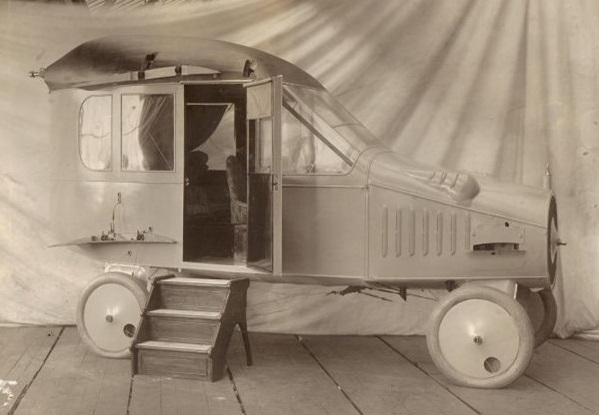
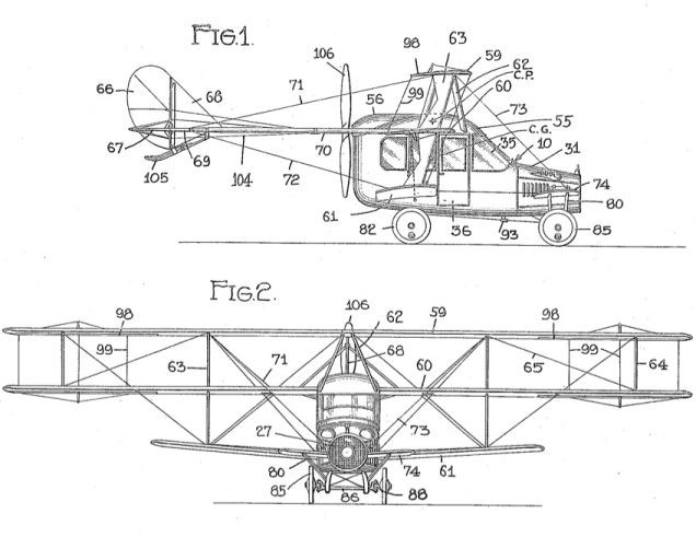
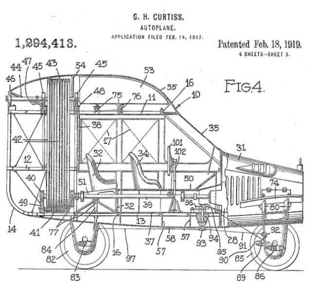
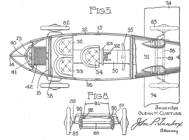
The Curtiss Autoplane offered limousine luxury in its aluminium bodied ‘car’: comfortable leather seats for an aerial chauffeur and two passengers, tasteful trimming in plush brocade, tapestries, even velvet drapes for the celluloid windows. Exactly how its triplane wings and outrigger mounted tail unit detached for road use is not clear, but with a mass of rigging wires needing careful adjustment it can scarcely have been an easy or quick process. The 100 hp Curtiss OXX engine drove a four blade pusher propeller by means of a shaft and chain mechanism. A clutch took care of power transmission to the road wheels.

The Curtiss Autoplane was ceremonially unveiled at the New York Pan American Aeronautical Exposition in Grand Central Palace, New York, on 8 February 1917.The machine only flew once or twice from the Atlantic Coast Aeronautical Station at Newport, Rhode Island, before America’s entry into World War I intervened and curtailed further development in favour of weapons of war.

Curtiss N / N-8 / N-9 / O / Murray-Carnes / Burgess N-9

Curtiss N

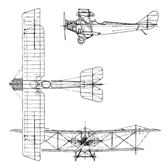
The 1914 Model N was a two-seat biplane similar to the Model J, differing in the airfoil and placement of the ailerons, which were mounted between the wings. It was powered by a 90-100 hp Curtiss OX inline engine. Due to legal issues with the Wright brothers over the use of ailerons, the sole Model N was modified by locking the ailerons and increasing dihedral to seven degrees in an effort to prove that aircraft could be flown without ailerons or wing warping. The Curtiss N Army trainer featured tandem “bathtub” cockpits, trailing interplane ailerons, and cost $7,500. One was delivered on 11 December 1914 (AS35) for Army evaluation but was judged very unstable despite added dihedral. A design merger with the Model J led to the famed JN-4 “Jenny.”

Four 1916 N-8 (Model 1D) variant with 41’9″ wing and standard ailerons were built; AS60-AS63.

The first flight of the Model N took place in 1915. The United States Army purchased the aircraft for evaluation, but Curtiss repossessed it due to legal issues with the Wright brothers.

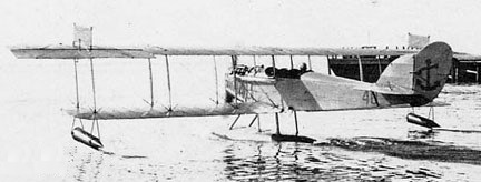
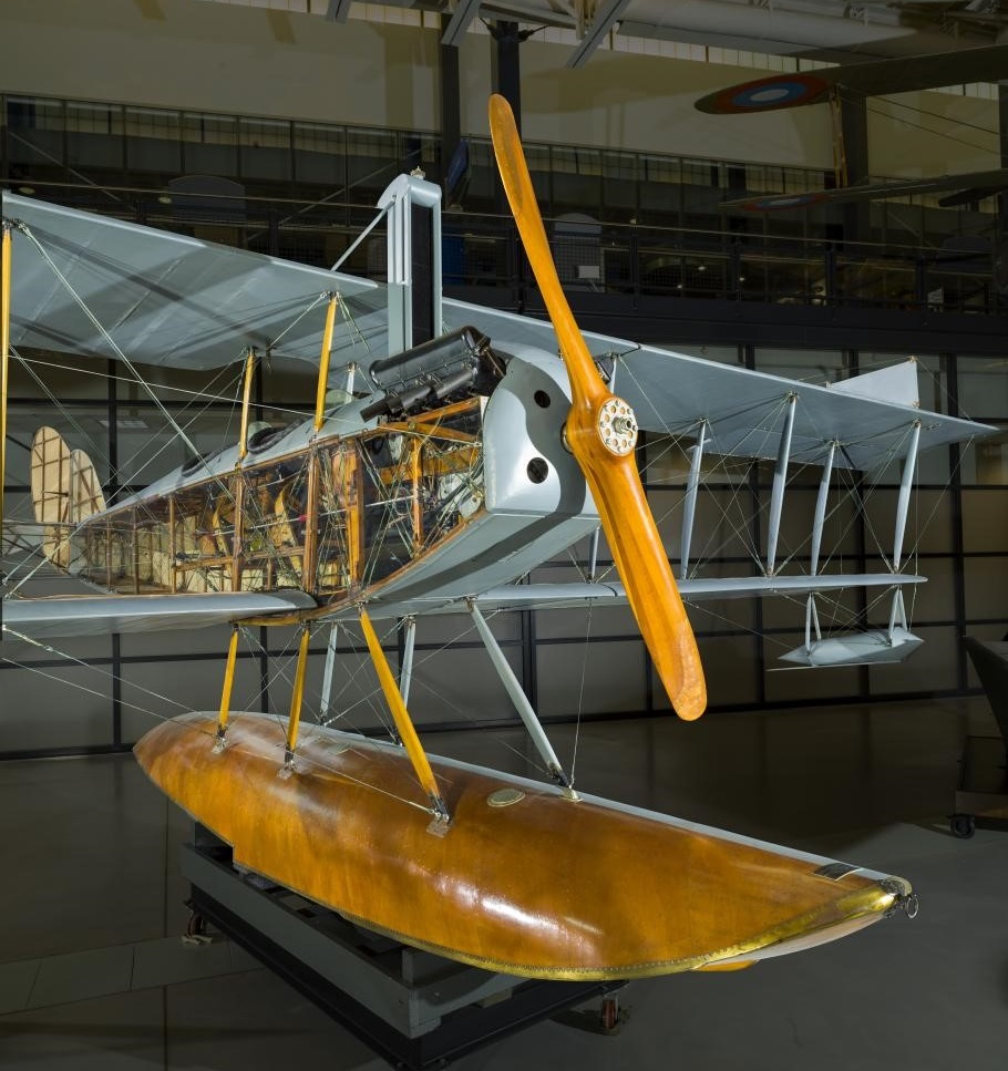
Developed in late 1916, the N-9 (Model 5) enlarged N was the seaplane version of the JN Jenny. To make the conversion, a single large central pontoon was mounted below the fuselage, with a small float fitted under each wingtip. It had a heavier engine than the Jenny to compensate for the extra weight of the floats and an upper wing that was some 10 feet (3 meters) longer than the lower one. Further modifications to the standard Curtiss JN-4 design were required to cope with stability problems that emerged in the N-9. They included lengthening the fuselage, increasing the area of the tail surfaces, and installing stabilizing fins on the top of the upper wing. The N-9 was initially powered by a 100-horsepower Curtiss OXX-6 engine. The U.S. Navy made use of wind tunnel data developed at the Massachusetts Institute of Technology in its redesign the JN-4. The N-9 was the first U.S. Naval aircraft to incorporate wind tunnel data directly into its design.

N-9H

The one model N built for US Army was later rebuilt as Model O with side-by side seating.

The Curtiss Aeroplane and Motor Company of Garden City, N.Y., received a Navy contract for thirty N-9s in August 1916. Another fourteen were ordered by the U.S. Army, as it was also conducting seaplane operations at that time. The 100-horsepower N-9 was satisfactory for pilot training, but it lacked the performance needed for bombing operations and gunnery training. To meet these requirements, Curtiss replaced the OXX-6 with a 150-horsepower Hispano-Suiza, then being manufactured under license in the United States by the Simplex Division of the Wright-Martin Company, and later by Wright Aeronautical Corporation. This improved model was designated N-9H.

Curtiss N-9

A total of 731 were built; 122 by Curtiss (A60-A65, A85-A90, A96-A125, A201-A234, A294-A301, A342-A373, A2285-A2290), plus 681 subcontracted to Burgess Company of Marblehead, Massachusetts and also seen as Burgess N-9 (A409-A438, A999-A1028, A2351-A2572, A2574-A2650), and 50 by NAS Pensacola (A6528-A6542, A6618-A6632, A6733-A6742, A7091-A7100) from spare components and engines.

Although the consensus in early 1917 among aviators and even the N-9’s manufacturer was that the N-9 could not be looped, the pioneering early United States Marine Corps aviator Francis Thomas Evans, Sr., believed it was possible. On 13 February 1917, he flew an N-9 over the Gulf of Mexico off Pensacola, Florida, and began attempts to loop it. He succeeded on his fourth try, becoming one of the first persons ever to loop a seaplane (first pilot to loop a seaplane was Polish aviator Jan Nagórski on 17 September 1916 in Grigorovich M-9 flying boat). Lacking witnesses, he flew over Naval Air Station Pensacola and repeated the feat. In 1936, he received the Distinguished Flying Cross for this achievement. More important, however, were the stall and spin recovery techniques he discovered while flying the N-9 that day. During his first three loop attempts, the N-9 stalled before he reached the apex of the loop and fell into a spin. He found that by releasing back-pressure on the stick and aggressively applying opposite rudder to the direction of the spin he could change the spin into a normal dive and recover, something previously thought impossible in an N-9.

During the war, 2,500 Navy pilots were trained on the N-9. In addition to training a generation of Navy pilots, the N-9 was used to develop tactics for ship-borne aircraft operations in 1916 and 1917, using catapults mounted on armored cruisers. After the war, the N-9 was again employed to successfully demonstrate a compressed air turntable catapult. This type of catapult was later installed on battleships, replacing turret-mounted platforms for launching aircraft. In July 1917, several N-9s were acquired by the Sperry Gyroscope Company and were used as test vehicles for aerial torpedo experiments conducted for the Navy’s Bureau of Ordnance. The N-9 was withdrawn from the U.S. Navy inventory in 1927 after ten years of service.

The Brazilian Naval Aviation also operated the N-9H.

The Murray-Carnes was an all-steel development of the Curtiss N-9 requested by secretary Daniels of the Navy Department in 1918 from the J.W. Murray Mfg. Co. of Detroit.

The Hewitt-Sperry Automatic Airplane was a project undertaken during World War I to develop a flying bomb, or pilotless aircraft capable of carrying explosives to its target. Elmer Sperry, succeeded in arousing the US Navy’s interest.

After the US declaration of war on Germany, Sperry began urging the Navy to revisit the idea. The Naval Consulting Board supported him, and formally requested the Secretary of Navy to apportion $50,000 for the work. The government thus included the development of the flying bomb or aerial torpedo in its war preparations. The Senate went so far as to establish two classes for the type weapon, one for wireless control, the other for completely automatic operation. Final approval came on May 17, 1917, and the Navy agreed to provide five (later upped to seven) Curtiss N-9 seaplanes and to purchase six sets of the Sperry automatic control gear. Navy Secretary Josephus Daniels agreed to spend $200,000 on the project, with the money to be administered by the Bureau of Ordnance, the Bureau of Construction and Repair and the Bureau of Engineering. The operation was established at Copiague, Long Island.

In 1913, the Navy provided a flying boat to test and evaluate the gyro-based autopilot. Sperry’s son Lawrence served as an engineer during the test phase. In 1914, Lawrence Sperry was in Europe and observed the developing techniques of aerial warfare, including the use of aircraft. In 1915, the New-York Tribune broke the news of the project. In 1916, the two Sperrys joined Peter Hewitt, an early inventor of radio-related devices, to develop an explosive-laden pilotless airplane.

The system consisted of a gyroscopic stabilizer, a directive gyroscope, an aneroid barometer to regulate height, servo-motors for control of rudders and ailerons, and a device for distance gearing. These all could be installed in an airplane which could be catapulted or flown from the water, and would climb to a predetermined altitude, fly a pre-set course, and after traveling a pre-set distance, drop its bombs or dive to the ground. Wilkinson reported that the weapon did not possess a degree of accuracy sufficient to hit a ship, but, because of its range of 50 to 100 miles (80 to 161 km), it might be of interest to the Army.

The autopilot equipment was already designed, but the radio control system hadn’t been fully developed, so while the hangars were being built at Copiague, Sperry turned his attention to this aspect, purchasing rights to a number of patented radio-related inventions. Ultimately, though, the radio control systems were not used on the Hewitt-Sperry Automatic Airplane. Later, in 1922, the system was installed on several Verville-designed planes along with gear for the Army Air Services engineering division. These aircraft successfully hit their targets from ranges of 30, 60 and 90 miles (140 km).

The first test flights of an autopilot-equipped aircraft was in September, 1917, and took place with a human pilot on board to fly the takeoff. By November, the system successfully flew the aircraft to its intended target at a 30-mile (48 km) range, where the distance-measuring gear would drop a bag of sand. Accuracy was within two miles (3 km) of target.

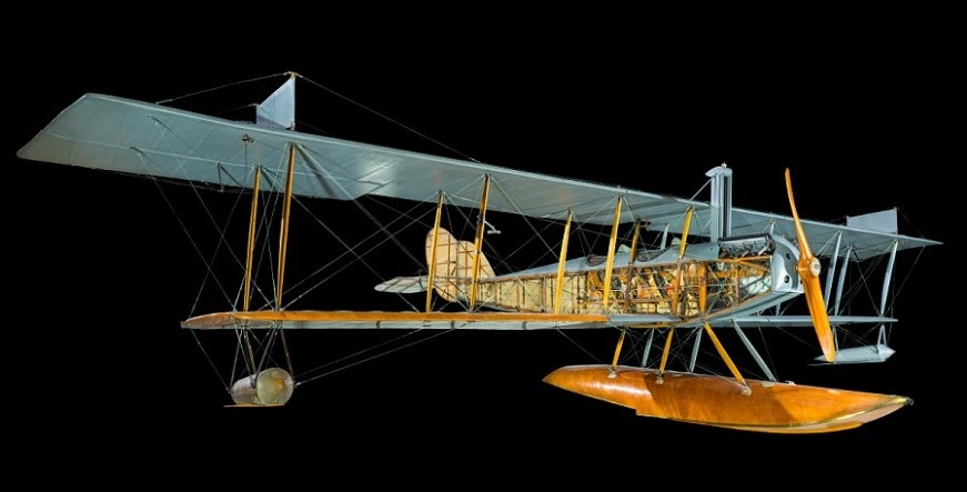
When the N-9 flight test program got started, it became apparent that a more efficient airframe was needed. Because war production deliveries could not be diverted, a special, rush order was placed with Curtiss in October, 1917, for six planes of unique design, with an empty weight of 500 lb (230 kg), top speed of 90 mph (140 km/h), range of 50 miles (80 km) and the capability of carrying up to 1,000 lb (450 kg) of explosives. They became known as the Curtiss-Sperry Flying Bomb. Because this was to be a design dedicated to the remote control concept, the planes were not equipped with seats or standard pilot controls.

Only one example of the type has survived, and is now a part of the National Air and Space Museum collection. Originally on display at the Museum of Science and Industry in Chicago, Illinois, it was later transferred back to the U.S. Navy pending transport to the National Air and Space Museum. The Naval Air Engineering Laboratory in Philadelphia, Pennsylvania, fully restored it in 1966.

N / N-9C
Original N-9, later known as the N-9C.
Engine: Curtiss OXX-3, 100hp (75 kW)
Wingspan: 38’3″
Length: 27’2″
Speed: 70 mph
Seats: 2

N-8
Production version of N for US Army, Equivalent to JN-3.
Engine: 90 hp (67 kW) Curtiss OX-2
Four built 1915

N-9
Engine: 100hp OXX-6
Wingspan: 53’4″
Length: 30’10”
Useful load: 625 lb
Max speed: 80 mph
Cruise speed: 70 mph
Range: 180 mi
Seats: 2

N9-H
Engine: Wright-Hisso, 150 hp (110 kW)
Propeller: 2-bladed fixed-pitch wooden
Wingspan: 16.2 m (53 ft 4 in)
Wing area: 496 sq ft (46.1 sq.m)
Length: 9.4 m (30 ft 10 in)
Height: 3.3 m (10 ft 9 in)
Weight: Empty weight: 973 kg (2,140 lb)
Gross weight: 1,257 kg (2,765lb)
Useful load: 625 lb
Maximum speed: 78 mph (126 km/h, 68 kn)
Cruise speed: 70 mph
Service ceiling: 6,600 ft (2,000 m)
Time to 3,240 ft (990 m): 10 minutes
Range: 180 mi
Seats: 2

N9-M

N-9N
Engine: 150 hp (112 kW) Wright A

Curtiss JN Jenny / JN-4

JN-4D

In 1914 Curtiss lured B. Douglas Thomas from Sopwith to design the Model J trainer, which lead to the JN-4.
The JN-4 was developed from the JN-2, via the interim JN-3 which had featured unequal-span wings with ailerons on the upper wing only and introduced a wheel-type aileron control system. Redesigned vertical tail surfaces had a fin and rudder assembly with contours which were to be largely retained in the JN-4. The UK bought 91 JN-3s and the US Army two. Several JN-2s were converted subsequently to JN-3 standard by the incorporation of JN-3 wings and vertical tail surfaces and by installation of the 75kW Curtiss OXX engine. Total production was no more than 100, a dozen built at a newly-built Toronto factory.

Flying the Curtiss JN-4

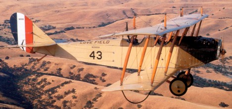
The JN-4 in its original form closely resembled the JN-3, retaining the same unequal-span two-bay wing and cross-axle landing gear. It first appeared in July 1916 when 105 were sold to the UK and 21 to the US Army. Others were purchased by private owners and a number were operated by the Curtiss company’s flying schools. As a result of British experience with the JN-3 and JN-4 the Curtiss company developed the JN-4A (retro-designated Model 1 in 1935), which incorporated a number of improvements (larger tailplane and engine downthrust). A total of 781 was completed, 87 of them at the Curtiss Canadian factory. The US Army bought 601, the US Navy five and the rest were exported to the UK. The JN-4B (Model 1A) appeared in late 1916, just before the JN-4A. It differed in several design details (it introduced-the larger tailplane and used the OX-2 engine), and found a number of private purchasers and flying schools as customers, added to which the US Army bought 76 and the US Navy nine.
Two examples of the experimental JN-4C were followed by the very successful JN-4 Can and JN-4D (Model 1C). The JN-4 Can had been developed from the JN-3 by the Curtiss company’s Canadian associate, Canadian Aeroplanes Limited, and soon became known as the Canuck. Production totalled 1,260 of which 680 went to the US Army while the bulk of the remainder became the standard Canadian primary trainer. The JN-4 Can served with the Royal Canadian Air Force until 1924, while privately owned aircraft remained in use into the 1930s. John Ericson, chief engineer of Canadian Aeroplanes Ltd, assembled 127 aircraft in 1927, most of them reconditioned aircraft incorporating many parts which had been held in stock. Some had a third cockpit and were known under the designation Ericson Special Three.


The Curtiss JN-4 two-seat biplane soon acquired the nickname ‘Jenny’ which was used widely during the inter-war years. It was one of the most significant American aircraft of its time. From April 1917 when the USA entered World War I it was built in large numbers and used to train some 95% of all American and Canadian pilots. It achieved renewed fame from 1919 until the late 1920s, when thousands were flown in the barnstorming era, thrilling spectators at travelling aerial pageants and shows throughout the United States.

JN-4H

The JN-4D appeared in June 1917 and went into large-scale production, 2,812 being built between November 1917 and January 1919. With an urgent need for efficient trainers in wartime conditions the production involved six other US manufacturers.

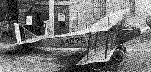
The St. Louis Aircraft Corporation became one of six across the country to produce the Curtiss JN 4D Jenny with first deliveries in 1918. The first order was for 200 planes, the company delivered 30 aircraft per month, and 57 JN 4D October 1918. The St. Louis Car went on to manufacture 450 JN-4D Jenny trainers for the U.S. Army.

JN-4D Army trainer set up for publicity photos outside St. Louis Aircraft plant in 1918

As well as several new features, the JN-4D combined the more successful elements of both the JN-4 Can and JN-4A designs (stick control of the former, in place of the Deperdussin system, and the lines and engine downthrust of the latter). The end of World War I led to cancellation of contracts for 1,100 examples of a JN-4D-2 version, which had a number of modifications requested by the US Army. In the event, only the prototype was delivered to the military authorities, although several were sold to civil operators in 1919.
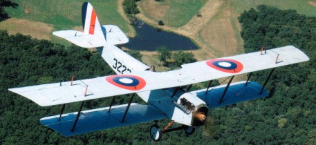
In a bid to provide an advanced trainer to meet urgent wartime needs, the JN-4D was re-engined with the more powerful 112kW (150-hp) Hispano-Suiza built by the Wright company. The resulting JN-4H (Model 1E) was in production from the end of 1917 to the November 1918 armistice, 929 being delivered to the US Army. The JN-4H was completed also in dual-control (JN-4HT), combing (JIM-4HB) and gunnery trainer (JN-4HG) versions.
The one-off JN-5H advanced trainer was built to a US Army requirement, but was rejected in favour of the Vought VE-7. It was developed into the JN-6H (Model 1F) which had a strengthened aileron control structure. The US Army purchased 1,035 JN-6Hs, subsequently passing five examples to the US Navy. The aircraft delivered to the US Army were built in sub-variants specialised for various training functions. (JN-6HB single-control bomber trainer, JN-6HG-1 dual-control trainer, JN-6HG-2 single-control gunnery trainer, JN-6HO single-control observation trainer and JN-6HP single-control pursuit [fighter] trainer).
With the armistice the production was stopped, after more than 6000 were produced, mostly of the “D” model.
As part of the post-war economy drive the US Army was forced to modernize the ‘Jenny’ rather than purchase new designs. This task was allocated to US Army Service Depots, which upgraded many of the earlier versions until 1926. The revised aircraft all used Wright-built 134kW Hispano-Suiza engines and were redesignated JNS (standing for JN Standardized). Between 200 and 300 JNS trainers were completed.
The US Army used JN-4As, JN-4Ds and JN-4 Can primary trainers until 1919. The higher powered JN-4Hs and JN-6Hs remained in service until they were phased out in favour of new types in the mid-1920s, the last Jennies being withdrawn from US Army service in 1927.

Tallman & Mantz Jenny movie line-up in Navy markings

From 1919 onwards Jennies had been sold to private owners, many who used their aircraft as stunt pilots in travelling circus or barnstorming. The Jenny also featured in many Hollywood films of the 1920s and early 1930s. A considerable number of Jennies survive in museums and several in private ownership are maintained in flying condition in the USA.

JN-4D Jenny

Ultralight replica:
Early Bird Aircraft Jenny

Gallery

Curtiss JN-4D
Engine: 1 x 67kW, 90 hp Curtiss OX-5 inline piston
Max take-off weight: 871 kg / 1920 lb
Empty weight: 630 kg / 1389 lb
Wingspan: 13.30 m / 43 ft 8 in
Length: 8.33 m / 27 ft 4 in
Height: 3.01 m / 9 ft 11 in
Wing area: 32.70 sq.m / 351.98 sq ft
Max. speed: 121 km/h / 75 mph
Cruise speed: 97 km/h / 60 mph
Ceiling: 1980 m / 6500 ft
Range 200 miles / 320 km
Seats: 2

JN 4H
Engine: Hispano-Suiza, 150 hp

Curtiss JN-4

Curtiss F / Alexandria 10

Model F

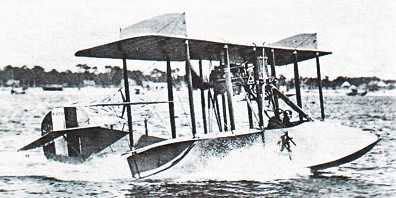
The definitive 1913 Model F was of wooden construction, the two-bay biplane had inter-plane ailerons on each side, fabric-covered wings and tail unit, and a carefully contoured single-step plywood-covered hull which accommodated two side-by-side in a cockpit location just forward of the wings. Power was a 56kW Curtiss O engine driving a pusher propeller. The engine being mounted on struts just below the upper wing centre-section.

The Curtiss F two-seat biplane flying boat became the Army’s first flying boat. This basic design was ordered by the US Navy, and after the United States entered World War I on 6 April 1917 it was adapted as the service’s standard primary training flying-boat, 144 more being ordered. During the war, Curtiss received so many orders for flying boats that he hired Boeing and Loughead (later renamed “Lockheed”) to build them to his specifications.

Alexandria was contracted Curtiss F-boats for USN, as the Alexandria 10, circa 1917. Thirteen were built; A2651 to 2653, A5024, and A5247 to 5256
The F was also sold to several civil owners.
The 1914 version of the Model F had rounded wingtips, a tougher hull and increased strut support for the engine to prevent it collapsing on the crew in the event of a crash.
The 1917-18 version of the Model F eliminated the original shoulder-yoke type aileron control in favour of a more conventional arrangement; and some aircraft had the ailerons transferred to the upper wing from the interplane position, span of the upper wing being extended. Several ambulance conversions flew with provision for a stretcher patient to be carried above the hull behind the cockpit. The more powerful Curtiss OXX-3 engine was fitted from 1917 onwards.
The Model F, particularly in its earlier versions, was sold to a number of foreign navies. Russia obtained a considerable number for operation in the Baltic and Black Seas. The Italians also flew the Model F and eight examples were licence-built by the Zari company at Bovisio.

Engine: 1 x 75kW Curtiss OXX-3 inline piston
Take-off weight: 1116 kg / 2460 lb
Empty weight: 844 kg / 1861 lb
Wingspan: 13.75 m / 45 ft 1 in
Length: 8.48 m / 27 ft 10 in
Height: 3.42 m / 11 ft 3 in
Wing area: 35.95 sq.m / 386.96 sq ft
Max. speed: 110 km/h / 68 mph
Range: 1370 km / 851 miles

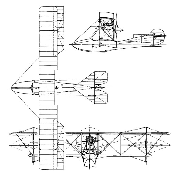
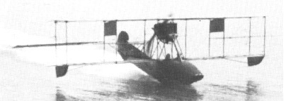
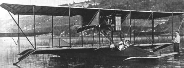
Curtiss Hydroaeroplane / C-1 / AB-1

The Curtiss Flying Boat was an early “hydro-aeroplane” or seaplane that was first concept tested by well-known aviator Glenn Curtiss in January 1912 in San Diego. By the end of the same year, Curtiss had built his first successful flying boat at Hammondsport, NY and succeeded in selling the aircraft to the Navy. The Navy first acquired five Curtiss Flying Boats, then an additional 144 for training before the original F type model was supplanted by the MF in 1918.

The C-1, the Navy’s first flying boat, was tested at Hammondsport, N.Y., by Lieutenant T. G. Ellyson on 30 November 1912. Its performance, as informally reported by Ellyson, was: “Circular climb, only one complete circle, 1,575 feet in 14 minutes 30 seconds fully loaded. On glide approximately 5.3 to 1. Speed, eight runs over measured mile, 59.4 miles per hour fully loaded. The endurance test was not made, owing to the fact that the weather has not been favorable, and I did not like to delay any longer.”

The Curtiss C-1 (changed to AB-1 in 1914) made the first catapult launch by a flying boat in December 1912.

On 27 March 1914 the original designations of aircraft were changed to two letters and a number of which the first letter denoted class, the second type within a class, and the number the order in which aircraft within class were acquired. Four classes were set up; A for all heavier-than-air craft, D for airships or dirigibles, B for balloons and K for Kites. Within the A Class, the letters L, H, B, X and C represented land machines, hydroaeroplanes, flying boats, combination land and water machines, and convertibles respectively. Thus the third hydroaeroplane, formerly A-3, became AH-3, and the first flying boat, formerly C-1, became AB-1.

The first Curtiss Flying Boat acquired by the Navy was designated C-1, before it was changed to AB-1 (A for Curtiss and B for flying boat) as the Navy began to procure aircraft from other corporations. The C-1 was based at the Navy Yard in Washington, D.C. in 1912 before moving to Guantanamo Bay, Cuba.

Curtiss Flying Boat Nr.2 / E / Flying Fish

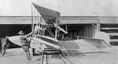
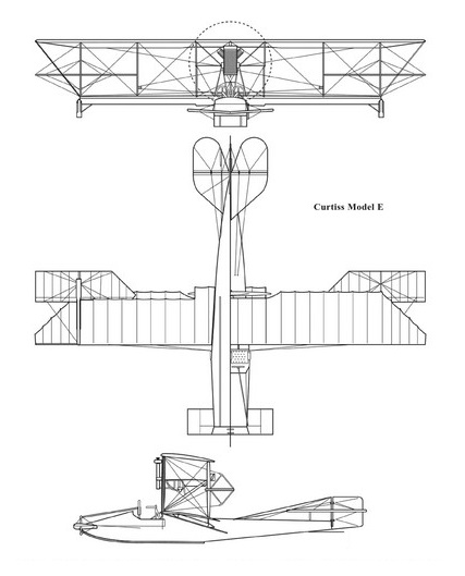
Curtiss left San Diego in the spring of 1912 to return to Hammondsport, where he commenced work on Flying Boat No.2 during the spring of 1912, which, in its original configuration, utilised standard components of the 1911 model E land and hydro (float) plane, including twenty-eight foot, eight inch single surface, equal span wings and a pusher mounted 75 hp Curtiss O V-8 engine. Its flat-bottomed, scow-type hull, unlike Boat No.1, extended all the way aft to support an empennage consisting of a long-chord fin and rudder with cruciform horizontal surfaces. To reduce the danger of sinking after hard landings, the hull was constructed with six watertight compartments.

Initial trials were not successful, as Flying Boat No.2 could not be made to unstick from the water at takeoff speed. After observing numerous attempts, Curtiss modified the hull to incorporate a step just behind the centre of gravity. The step produced a reduction in hydrodynamic drag by lifting almost half of the hull free of the water and increased lift by permitting the nose of the aircraft to be rotated up to a positive angle of attack.
Other changes made included standpipes that bled air into the cavity behind the step, a secondary canard elevator on the nose (later removed due to control problems), and triangular extensions to the upper wing to increase lift.

Flown by Glenn Curtiss on 26 January, 1911, the first practical seaplane. By the fall of 1912 Curtiss had made sufficient progress with the design to sell the Navy its first boat-hulled aircraft, entering service in late November as the C-1 (changed to AB-1 in 1914). This aircraft made the first catapult launch by a flying boat in December 1912.

The first E boat mid-1912 with front stabiliser

The first seaplane was maneuverable, light, and relatively fast, and was the most widely built type of plane in the United States before World War I.

The Army’s S.C.15 in 1913. This aircraft is thought to have F-type wings but is identified as an E boat.

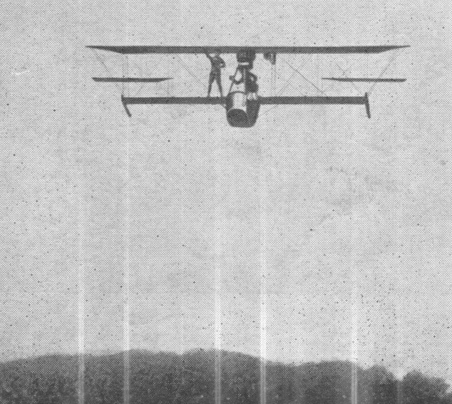
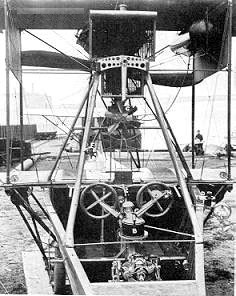
Later model E flying boats featured deepened, V-bottom hulls with a more pronounced step, as well as more powerful engines, a larger rudder, and a diagonal strut in front of the motor mount to prevent the engine from leavin its mounts in hard landings. Besides the Navy’s C-1, a number of E boats were built for the Army and the Curtiss Flying School, plus two or three more to civilian purchasers, one of which was used by Lawrence Sperry during 1944 to conduct the first experiments of an airborne gyroscope.

Lawrence Sperry flew his Curtiss over Paris in 1914 with his hands off the controls and his passenger standing on the wing to prove the efficiency of its automatic pilot.

Lawrence Sperry over Paris in 1914
Sperry-Curtiss E

Model E
Engine: 1 x 75-100 hp Curtiss OX
Prop: 2 blade fixed pitch wood
Empty weight: 1490 lb
Take-off weight: 2500 lb
Wingspan: 37 ft 9 in or 40 ft 0 in
Length: 27 ft 2 in
Wing area: 350 sq.ft