Williams Research WASP / X-Jet

In the mid-1960s, engine manufacturer Williams Research developed a light turbofan engine, the “WR19”, with a thrust of 1.91 kN (195 kgp / 430 lbf), which was used in a “flying belt” that could be strapped on somebody’s back to allow flights of up to 20 minutes. It was a sexy toy but of no particular usefulness, and it was canceled in 1969.

Williams continued to tinker with the idea, coming up with a one-man flying platform powered by the WR19 or a derivative engine, known as the “WASP”, which was later renamed the “X-Jet”. This machine looked something like a flying trashcan on skids, and could carry a pilot directing the machine with two grip-type controls. It was evaluated in the 1980s; videos of its flight suggest it performed very nicely and was easy to handle. Noises were made about a more capable successor, but apparently its endurance was too limited and, as was the case with most of the other one-person flying machines, it was hard to understand that it offered any utility proportional to its expense and complexity.

One X-Jet is now on display at the USAF Museum in Ohio, while another is on display at the Seattle Museum of Flight. The WR19 and its descendants did prove to be useful powerplants for long-range cruise missiles.

Williams Model 2

In early 1912, Osbert Edwin Williams created his second aircraft, the Williams Model 2. Williams’ initial aviation involvement, was with Albert S. Beavers of Scranton, who constructed a monoplane in 1910, and later, a biplane in 1911.

The Williams Model 1 had been abandoned sometime during the winter of 1912; as the pioneer aviator, Elling O. Weeks, was making test-flights of the new Williams Model 2 Pusher Biplane, at Forty Fort, Pennsylvania, by 22 May 1912.

Initially, the Model 2 had a central front skid, and single vertical fin/rudder, hinged at the leading edge of the elevator, similar in concept to the Santos-Dumont Demoiselle (but, not quite. The Demoiselle had its empennage hinged about a central “universal joint-type” device). The seat for the pilot was offset to the port, and the engine was centrally mounted. A full length “side curtain” running the entire length of the interplane struts just to the starboard of the engine, was shortened to fill only the upper portion of the interplane gap, by July of 1912. Ailerons were fitted on all wingtips, and a large central radiator was mounted directly in front of the Curtiss engine. By the summer, the four-wheel main undercarriage had been revised to two larger main wheels fitted to a central axle. Earlier photos, apparently taken in the winter of 1912, and in May, show two sets of twin wheels, attached to skids, similar in fashion to a Wright Model B. The wings were cut back to the trailing edge spar, to allow clearance for the “pusher” propeller. It was necessary to do this, owing to the location of the engine, and in order to obtain a proper center-of-gravity.

On 15 September 1912, the Model 2 suffered a serious accident and much damage; necessitating a reconstruction of the airframe. By November, the Model 2 was back in action, making aerial deliveries of newspapers. As rebuilt, the biplane sported a twin-wheel main undercarriage, a nosewheel, and twin, rectangular vertical rudders, now mounted at opposite ends of the elevator, replacing the earlier curved, centrally-mounted vertical rudder. In order to allow the rudders to move “in”, the elevator’s trailing edge span was reduced to allow inward motion. The offset pilot seat, and wheel-type controls, were retained, and the number “7″ was prominently displayed on the vertical rudders, in a photo taken on 20 November 1912. The ailerons were also increased in chord, and the interconnecting strut between upper and lower ailerons, was retained.

The Model 2 was the first aeroplane to be fitted with a pitot tube-type airspeed indicator. Williams’ invention, described in the November 1912 issue of Aeronautics (p 151) shows that it was a basically manometer, coupled with a ram-air tube, forcing a fluid up a vertical tube to indicate airspeed. Indeed,

It is certain that the Model 2 design continued to evolve for several years into several different variants. In 1913, the earliest Model 2 was used in the October 1913 New York Times “Aerial Derby.”

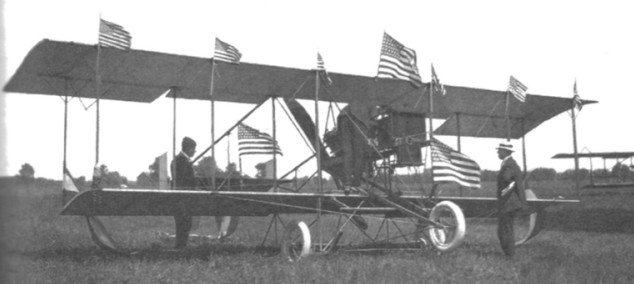
By 1915, Williams was operating a flying school at Long Lake, Fenton, Michigan; having relocated from Flint, Michigan. A solitary photo exists, taken there, which shows three incarnations of the Model 2. There was a two-place variant, with dual controls mounted on either side of the engine, and horn-balanced ailerons. A long-span variant used at the 1915 Michigan State Fair, and a variant with an extended upper span, and no lower wing ailerons. The last, apparently built in 1915, and known as; “The Banner.” It had thicker tires, and ailerons fitted to the upper wing, only. The “mystery plane” photo, shows this aircraft adorned with American flags at the August 1915 St. Clair County Fair at Port Huron, Michigan. But, while this machine was flown on throughout the country, the school machine, fitted with distinctive horn-balanced ailerons on the upper wingtips, was used into 1916.

Unfortunately, the only surviving, verifiable dimensions of the Model 2, are the dimensions of the Rome Turney radiator (30″ high, without the filler neck, and 3″ thick, at the core), and the diameter of the propeller (7′, curiously, almost the same as the 7′ 7″ diameter of the Beavers 1911 Biplane/Williams Model 1). But, there is also the curious story of W.P.A. Straith to contend with.

In additon to the aircraft he built, O.E. Williams also built a 125 hp eight-cylinder, water-cooled vee-type engine, similar to a 100 hp Curtiss Model O, the engine he apparently used throughout the career of the Model 2 (the Model 1 may have retained to 40 hp Rutenberger auto engine from its days as the 1911 Beavers Biplane). There were many notable graduates of the Williams School of Aviation. Among them; Clayton J. Brukner and Elwood Junkin of Waco fame. Lt. J. Thad Johnson, Lt. Cyrus Bettis, and Capt. E.G. Knapp, to name a few others.

Following a business dispute, and a change of the company name from the O.E. Williams Aeroplane Company to the Flint Aircraft Co., Inc.; Williams loaded his family into his 1916 Saxon touring car (which had fallen through the ice of Long Lake earlier that year), and relocated to Mobile, Alabama in 1917. At Mobile, Williams apparently constructed another Model 2, with an extended upper wing, fitted with horn-balanced, ailerons. Notably, the engine bearers were extended, as they were in the Straith Biplane. It was there, on 25 October 1917, that O.E. Williams was killed during an exhibition flight; flying at dusk in heavy winds.

Williams Model 1

The Williams Model 1 appears to have been a 40hp Curtiss pusher powered biplane, purchased from Beavers. Whatever the case, the Model 1 had been abandoned sometime during the winter of 1912; as the pioneer aviator, Elling O. Weeks, was making test-flights of the new Williams Model 2 Pusher Biplane, at Forty Fort, Pennsylvania, by 22 May 1912.

Williams held several U.S. patents, and his application for an aircraft windscreen, is accompanied by a 6 January 1912 photo of what is almost certainly the second (or third) incarnation of the Model 1. In this form, the span is probably much longer than the Model 2. The rear vertical rudder is rectangular, and a monoplane canard is fitted. Additionally, the undercarriage consists of twin main skis, a rear ski, and a single front wheel; the overall aircraft appearing to be a Curtiss-type. Nevertheless, it is worth noting that a photo in the Scranton Times (Tuesday, December 5, 1911, cover) appears to show the same aircraft, clearly a Curtiss-type, fitted with an all-wheel undercarriage. Thus, we can conclude that Williams’ first aircraft was not a monoplane, but was a Curtiss-type biplane. In fact, the January 1911 description of the Beavers Biplane in Aeronautics, does appear to describe a Curtiss-type, and does match-up with the Scranton Times photo; the exception being the addition of the monoplane canard, revised flight controls, and elimination of the rear biplane elevator; long after the January 1911 Aeronautics article was published.

Although the first of Williams’ aircraft was not of his or his wife’s design—the builder was described only as “a local resident”—its airworthiness was so marginal that Williams modified and improved it to such extent that it might as well have been his. In final form it had a 60hp Curtiss, 31’0″span, Farman-type gear and trailing-edge ailerons, and flew successfully in exhibitions.

Williams Helicopter 1908

1908 J Nwton Williams

A 1908 helicopter designed by Williams and shown here assembled at Hammondsport NY with what appears to be a 40hp Curtiss B8 motor, the same as used on the AEA Red Wing. Possibly achieved brief tethered flight.

A single place helicopter project, believed to have involved Williams, was underway in Connecticut circa 1924 — the only information comes from two photos showing a prototype or a test stand. The engine looks like a LeRhône rotary. Coaxial, contrarotaing rotor system. The two-blade rotor wings were attached rigidly to an elongated hub using two offset spars.

Williams Helicopter 1907

J Newton Williams first design of a single-rotor helicopter, based on the French Vuitten- Huber, failed to fly with its 8hp Curtiss motor, but further experiments in league with Emile Berliner produced a two-engine, two-bladed (rotor: 18’8″) machine weighing 460 lb that lifted the 150-lb Willams off the ground in a tethered flight on 26 June 1909.

Engine: 63hp Adams-Farwell

Williams Texas-Temple / Commercial-Wing / Speed-Wing / Sport / Sportsman

Williams Texas-Temple Commercial-Wing N3801

In 1926 a prototype of the Commercial-Wing was designed by George Carroll and George Williams and built. A single place, open cockpit, high wing monoplane, it was powered by an 80hp (later 120hp) LeRhône rotary engine.

Designed by George Carroll and George Williams, four planes were made with the Wright engine (c/n 101 registration NC173, c/n 102 registration NC2506, c/n 104 registration NC5185, c/n 105 registration NC138N), one with a Hisso (c/n 103 – registration NC3801), and one with a 100 hp Curtis OXX-6. This later one could be a Sportsman or the NC6525 registration aircraft.

The 1927 Texas-Temple Commercial-Wing cost $10,500 with an inertia starter, brakes and metal prop.

The 1928 Speed-Wing carried 1 passenger and was a Commercial-Wing for carrying mail. It took a 500 lb payload over a 500-mile range. The plane cost $9,500. It was advertised as a 1 or 2 person sportplane. The first plane was powered by a 150 hp Hisso A engine and had a 39’4″ wingspan. No registration found, but it could be the Commercial-Wing registration NC3801.

Continental Airways of Cincinnati used the Temple Company’s Commercial-wing model almost exclusively. Other models followed, including the much-ballyhooed Sportsman. The Sportsman was touted by British aviation enthusiast Lady Mary Heath as “the best performing airplane its class today.” Her endorsement might mean more to history if Lady Heath had ever met an airplane she didn’t like. During her stay in America, she declared every plane she flew to be a marvel of aviation engineering.

A contract that might have saved the company – delivering air mail between Dallas and Fort Worth and San Antonio and Houston — was awarded instead to Bowen Air Transport. Bowen then took over a hangar at Meacham Field in Fort Worth, a hangar Temple Aero had bought.

The Depression hit the aviation industry early and hard. Companies that had signed contracts with Texas Aero were hard-pressed to honour those contracts.

Operating exclusively out of Temple, Aero scaled back its operation to concentrate exclusively on production of the Sportsman model and the training of student pilots. Three 1929 Sport / Sportsman were built: prototype N480 c/n 1, N852H, and N987N c/n 107.

Commercial-Wing
Engine: 220 hp Wright J-5
Wing span: 39’4″
Length: 25’10”
Useful load: 950 lb
Max speed: 130 mph
Cruise speed: 112 mph
Stall: 35 mph
Range: 550 mi
Ceiling: 18,500 ft
Seats: 2-3

Sport / Sportsman
Engine: Cirrus Mk III, 100hp
Seats: 2

Speed-Wing
Engine: Hisso A, 150hp
Wingspan: 39’4″
Useful load: 1055 lb
Payload: 500 lb
Max speed: 135 mph
Cruise speed: 120 mph
Stall: 42 mph
Range: 500 mi
Seats: 1-2

Williams Mk.4

As the designation infers, the Williams Mk.4 is the fourth aircraft from the hands of the late Geoff Williams, a well-known Otago identity who did not like to conform to the rules. It was finished about 1990, first flew in 1991 and had logged over 160 illegally flown hours prior to its sale to Bob Gibson in June 2002. This aircraft was legally registered as ZK-JPA on 25 February 2003.
Geoff Williams never flew again after the third aeroplane, but resolved to build a fourth aircraft. This is the aircraft Bob Gibson bought. This plane was not difficult to fly he did have a few minor landing faults.
Geoff’s ambition was to fly his aeroplane around Fiordland coastline, landing at somewhere like Jackson’s Bay for refuelling and to this end he built a heated cabin and fuel capacity of over 100 litres and a locker where he could hold an additional 10- or 15-litre can. Sadly this was never to be realised as Geoff became ill March 2002 and died on 10 May 2002. It was Geoff’s wish that his plane be kept flying, and Bob seemed to be the person most interested.

Wingspan: 30 ft
Engine: Rotax 447
Prop: 3-blade Warp Drive
Cruise: 60 kts
Stall: 22 kts
Seats: 1
ROC: 500 fpm
Fuel burn: 12 lt/hr