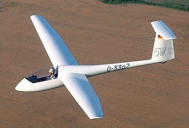
The G-102 Astir is a single seat glassfibre Standard Class sailplane, designed by Burkhart Grob. It was the first Grob-designed sailplane.
Construction of the prototype Astir CS began in March 1974. It features composite (fiberglass/resin) construction, a large wing area, a T-tail and water ballast. A Standard Class Sailplane, the large wing area gives good low speed handling characteristics. The main gear retracts. It first flew on 19 December 1974 and it went into production in July 1975 and soon proved to be popular, a total of 534 being delivered.
The cantilever mid wings have glassfibre roving main spars and a glassfibre/epoxy resin sandwich skin except for the ailerons, which are of glassfibre sandwich. There are Schempp-Hirth aluminium air brakes in the wing upper surfaces, but no flaps, and up to 220lb of water ballast can be carried in tanks in the wings, being jettisoned via a dump valve in the fuselage. Rigging is carried out without any separate removable parts as the wings and the tailplane are attached by a system of ‘snaplock’ connectors. The glassfibre semi-monocoque fuselage has a towing/launching hook, and the large one-piece cockpit canopy opens sideways to starboard. Construction of the T-tail unit is the same as that of the wings.
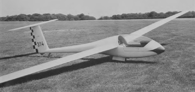
This was followed by the Club II with similar fixed gear. A slightly improved version, the CS-77, was introduced in 1977. The CS-77 has a different rudder profile fuselage similar to that of the Speed Astir. The Astir CS 77 made its first flight on 26 March 1977; nearly 400 of the CS 77 and Club Astir had been built by the end of 1978.
The Club Astir II and the Standard Astir II featured the new fuselage of the Speed Astir II. with a one piece canopy, as well as the elasticated flaps of the Speed version and a new wing tip profile.
The Astir CS 77 has a retractable monowheel with an internally-expanding drum brake located ahead of the center of gravity, which folds up behind closed doors, and there is also a rubber-sprung tail wheel. The Astir CSM was a powered version under development in mid-1976 with a 25hp Fichtel & Sachs Wankel KM24 rotating piston engine on a retractable pylon aft of the pilot, driving a two-blade Hoffman tractor propeller. A 6.6 gal fuel tank is fitted.
G-102 Astir
The Astir CS Jeans was of similar configuration to the CS 77, but with fixed wheel, and a tailskid.
The Standard III followed in the early 1980’s reverting to the higher profile fuselage and with reduced empty weight and increased payload. The Club III has a fixed main gear ahead of the center of gravity, and a tailwheel. The Club IIIB has a cockpit almost identical to the front seat of the two-place G 103 Twin II with a fixed main gear aft of the center of gravity and a nosewheel. Air Transport Certified (except Club II which is EXP). One, flown by R.R. Harris of the U.S., won the world absolute altitude record at 14.938 m/ 49.009 ft in 1986.
Production variants were the Club Astir III, IIIB and Standard Astir III, which have a roomier cockpit and reduced empty weight.
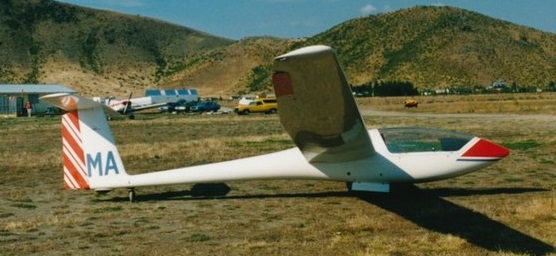
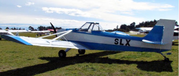
Grob G-102 Astir CS77 ZK-GMA
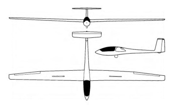
Grob 102 Wingspan: 15.00 m (49 ft 3 in) Wing area: 12.4 sq.m (133 sq.ft) Water ballast: 50 kg (110 lb) Aspect ratio: 18.2 Empty weight: 255 kg (561 lb) Gross weight: 450 kg (990 lb) Maximum glide ratio: 38 Glide Ratio: 36 at 50 kt (92 km/h) / 5.9 nm (10.97 km) per 1000 ft Sink rate: 141 ft/min (0.71 m/s) at 50 kt Glide Ratio: 34 at 41 kt (76 km/h) / 5.6 nm (10.36 km) per 1000 ft Sink rate: 122 ft/min (0.62 m/s) at 41 kt At 90 knots (166 km/h) Glide Ratio: 23 at 90 kt (166 km/h) / 3.8 nm (7.01 km) per 1000 ft Sink rate: 393 ft/min (2.00 m/s) at 90 kt Stall: (without airbrakes) 32 knots (60 km/h) Stall: (with airbrakes) 35 knots (65 km/h) Never Exceed: 135 knots (250 km/h) In Rough Air: 135 knots (250 km/h) Manoeuvering: 92 knots (170 km/h) On Aerotow: 92 knots (170 km/h) On Winch: 64 knots (120 km/h) Airbrakes: 135 knots (250 km/h) Gear Down: 135 knots (250 km/h) Minimum Payload: 70 kg Maximum Payload: 110 kg Crew: One pilot
Grob G-102 Astir CS77 Span: 49 ft 2.5 in / 15.0 m Length: 21 ft 11.25 in / 6.69 m Height: 4 ft 7 in / 1.4 m Wing area: 133.5 sq.ft / 12.4 sq.m Aspect ratio: 18.2 Wing section: Eppler E603 Empty weight: 595 lb / 270 kg Max weight: 992 lb / 450 kg Water ballast: (220 lb / 100 kg Max wing loading: 7.43 lb/sq ft /36.3 kg/sq.m Max speed: 155 mph / 135 kt / 250 km/h Stalling speed: 32.5 kt / 60 km/h Max aero-tow speed: 105 mph Max rough air speed: 135 kt / 250 km/h Min sinking speed: 0.6 m/sec / 1.97 ft/sec at 47 mph / 40.5 kt / 75 km/h Best glide ratio: 38:1 at 65 mph / 56.5 kt / 105 km/h
In New Zealand, Gavin Grimmer’s own design, the Grimmer Skylux (c/n 1005-2) is a single seat glider towplane powered by a converted Lexus V 8 engine. It was registered on 10/12/12, at Hastings, New Zealand, as an Amateur Built Aircraft. Gavin has had a lot of experience with automotive engine conversions in homebuilt aircraft with his Maranda ZK-JGR (which has the c/n 1005-1).
Between 1915 and 1916 at the Shchetinin Factory and based on a Grigorovich project, two “land” models were designed (in Russian Sujoputnie and hence the S in the name as opposed to the M for Morskoi or naval). The objetive of these models was to increase the performance of the Farman biplanes that the factory built under license.
The first of these projects, known as S-1 (Григоровича С-1), was designed as a conventional biplane heavily influenced by Farman’s designs and equipped with a rotary engine. Construction was abandoned before the prototype was finished.
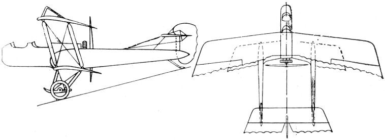
A second model, called S-2, was designed as a two-seater aerial observation and reconnaissance aircraft and generally repeated the successful scheme of the Farman biplanes with a central nacelle and a rotary engine. As a “novelty” it is worth noting the use of double tail cones that ended in individual empennages joined by the stabilizer with the elevators.
The selected powerplant was the 100 hp French Gnôme Monosoupape.
The entire construction was made of wood, covered with fabric. The wings had an Eifel-36 profile and were characterized by a large difference in span between both planes and the use of parallel uprights with cable tensioners.
The S-2 was built and its assembly was completed in January 1916. During flight tests, conducted by pilot Ya. I. Siedov, an accident occurred and the plane was not restored as it was considered that there was no point in trying to improve the outdated Farman designs
Attempts to modernize the M-5 flying boat gave no improvement and the objective could only be achieved through a totally new construction. Grigorovich decided to take on the task. The new design would see the light as MU-2 (Russian: Григорович МУ-2) or Morskoi Uchebni – 2 (Naval Trainer).
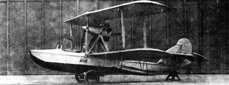
For the MU-2 Grigorovich selected the 100 hp Soviet M-11 engine. The hull was built entirely of metal and featured a new deck design with straight contours and an angular groove, which should give it good seaworthy characteristics, apart from being easier for production. The structure of the MU-2 contained 27 frames, of which 5 constituted the supports for the watertight compartments of the hull.
The wooden wing had a double spar structure with an Eifel-367 profile. The interplane uprights were also made of wood. Ailerons were on both planes.
The structure of the tail was made of duralumin, covered with fabric.
The shrouded M-11 radial engine sat on a pyramidal structure of metal tubes and drove a pusher propeller. The main fuel tank, with a capacity of 105 liters, was located in the hull, behind the cockpit. An auxiliary tank for direct supply to the engine, with a capacity of 11 litres, was located in front of it, protected by the elongation of the cabin. The transfer of fuel from the main to the auxiliary tank was carried out by a compressor or a manual reserve pump.
The MU-2 flying boat featured an open cockpit with a windshield for its two crew members sitting side by side. The control was by lever and the instrumentation was duplicated. The pilots’ pedals were synchronized.
Construction of the MU-2 began in 1927 at GAZ No.3 “Krasni Liotchik” from Leningrad and was completed without the presence of Grigorovich, who was in prison at the time.
During the construction process it was found that the MU-2 would be 150-200 kg heavier than the calculated values. The empty weight reached 820 kg, of which 220 corresponded to the hull. This was because the dimensions of the hull remained generally similar to those of the M-5, when according to the regulations, taking into account its metallic construction, they allowed a 10% decrease in size. Although the construction was quite careful, it was impossible to maintain the 660 – 700 kg of the project.
The tests of the flying boat began on August 29, 1929 at the testing station of Factory No.31 in Taganrog with the naval pilot ST Rybalchuk as responsible.
On September 6, 1929 the future of the MU-2 was discussed during a meeting of the Technical Committee of the Aviatrust. The most renowned shipbuilders of the time were present at this activity: Richard, Artamonov, Zhuravchenko, Samsonov, Chetverikov and Polikarpov.
MU-2 was reported to be at Taganrog, where the pilot Rybalchuk had executed the first flight. Preliminary results showed that the cabin was narrow, but the access hole was very wide. The flying characteristics of the flying boat were assessed by the pilot as rather poor and he also stated that the plane would not be able to get out of a spin. The climb did not stand out either, since the MU-2 reached 3,500 meters after 85 minutes of flight. The take-off run was quite long.
It was further noted that the centering of the MU-2 was similar to that of the Italian model Savoia S-16, located at 38% of the length, so it was proposed to carry out tests in the wind tunnel of the TsAGI and then proceed to improve the apparatus.
In practice nobody did anything to improve the MU-2. Shortly after, using this design as a basis, the builder of Factory No.23, A. S. Moscaliov, would present his project for a wooden-hulled training flying boat that would receive the name MU-3. This model was built during 1931 and later successfully tested, but would not go into series production as it was displaced by the Shavrov Sh-2.
Powerplant: 1 × 100 hp М-11 Wingspan: 11.80m Wing area: 35.60 m² Length: 8.60m Empty weight: 820kg Normal takeoff weight: 1086 kg Fuel weight: 90kg Maximum load capacity: 266 kg Wing loading: 30.5 kg/m² Power Load: 10.9kg/hp Maximum speed at sea level: 136 km/h Cruising speed: 108km/h Landing speed: 70km/h Practical range: 380 km Endurance: 3 hours Practical ceiling: 3150 m Time to 1000m: 10.8min Time to 2000m: 26min Time to 3000m: 53min Turn time: 18 sec Take-off run time: 35 sec Landing run time: 12 sec Accommodation: 2
At the beginning of 1924, a request was received from the Navy leadership to create a new naval reconnaissance flying boat. The technical task, delivered by the VVS Aviation Supply Department on June 13, specified the use of a Liberty engine, which is why the model was called MRL (Russian: Григорович МРЛ-1), after the acronym for Morskoi Razvietchiks motorom Liberty). although it has sometimes been named simply MR-1. In order to carry out this project, the development of an all-metal fighter was cancelled and 10,000 rubles were transferred to Grigorovich.
Work began in Moscow, but the development was moved together with the Grigorovich group to Leningrad.
Concept drawings, plans, and calculations were developed by engineers Piotr Dmitievich Samsonov and Kiril Alexandrovich Vigand. Since DP Grigorovich had left Factory No.1, design work was carried out in his apartment on Sadovo-Kudrinskaya Street. Work on the project began in June, and by September 18, 1924, it was submitted for evaluation. After reviewing all the documentation and verifying the coincidence of the requested benefits with the calculations, the Technical Scientific Committee of the Air Fleet approved the project. Shortly after, the instruction was issued to build the prototype of the flying boat at Factory No.3 “Krasni Liotchik” in Leningrad.
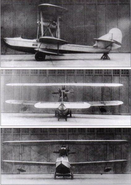
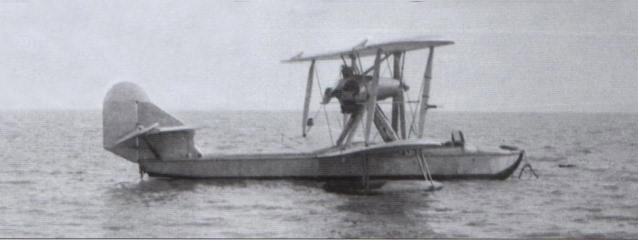
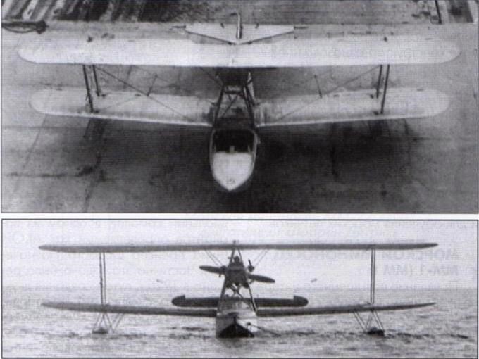
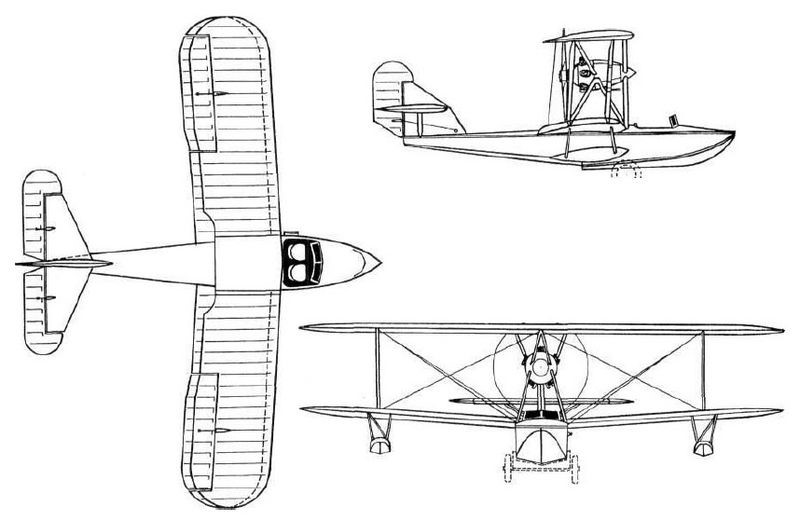
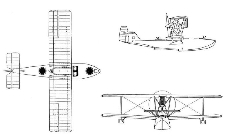
The MRL was designed as a four-seater biplane flying boat with a 400 hp Liberty engine driving a pusher propeller. The model had clean lines but it was very heavy.
The wings, with a Gottingen 436 profile, were rectangular in plan, with ailerons on the trailing edge of both wings. The upper wing was completely straight in its frontal view, but the lower plane had a certain positive dihedral and some small fixed stabilization floats were fitted. The interplane uprights were N-shaped with aerodynamic wood cladding and the necessary tension was achieved by means of cables.
The double-reinforced hull was very heavy and labor-intensive and expensive to build. With a total length of 9.8 meters and 4 meters to the first step, the width reached 1.5 meters and the maximum height 1.3 meters. The entire plywood hull was covered using 4 x 80 mm strips made from different types of wood and fixed using copper rivets with aluminum washers. The deck and the upper part of the rails were covered with pine wood boards, a little further down the rails were made of ash and walnut and from the waterline to the bottom of mahogany, which in this last area was installed with double layer. Between the plywood and the board covering, a layer of fabric coated with a waterproof lacquer was installed.
The tail was of the monoplane type with the stabilizers installed on a short keel and braced by simple struts. The keel ended in a small rudder. The rectangular stabilizer could change its angle of incidence in flight. The engine was installed on mounts in the center of the biplane wingbox and featured a cooling radiator located at the front.
The MRL-1 was designed for three crew members. Pilot and co-pilot sat side by side in an open cockpit, protected by a windshield. At the bow was a facility for a gunner operating a machine gun located on a ring mount. A second defensive post was located behind the power plant and was intended to defend the rear hemisphere.
The construction of the MRL-1 was completed at GAZ No.3 in Leningrad in May 1925. On June 6, the model was transferred to the naval base where it was assembled, adjusted and the first operations of entering the water were carried out.
From the first stage of the tests it was possible to verify that the front radiator was very small, so the necessary cooling of the engine was not achieved. The propeller was calculated for 1,700 revolutions/minute, but the engine at full capacity only guaranteed 1,550.
The first flight was made on June 2, 1925. After carrying out some test flights, it was concluded that in operations on water the model presented poor longitudinal stability and the take-off run was too long.
In the air the model behaved normally and was easily controllable. The maximum speed reached during the tests was 180 – 185 km/h at an altitude of 1000 meters.
During one of the last test flights, the oil tank burst and the aircraft was forced to make an emergency landing with the engine stopped. The cause of the explosion was the absence of an exhaust valve in the tank, which caused the oil to heat up and the pressure of the air accumulated there to increase, causing it to burst through the seam of the welds.
The tests included only 9 flights and were generally considered positive, since the model met the requested specifications, but the long take-off run and the problems when separating from the water were considered intolerable, so it was recommended to modify the design of the contours of the hull.
The ascent rate and the ceiling reached of only 3,050 meters were also noted as unsatisfactory.
Although the decision had been made to mass-produce the model, the request was eventually withdrawn. The only example built was delivered to the White Sea for exploitation, being used in the Solovietski Special Operations Camp (SLON) as a link with the mainland.
MRL-1 Powerplant: 1 x 400 hp Liberty Wingspan: 13.2m Wing area: 50.0 m² Length: 10.6m Empty weight: 1660 kg Maximum takeoff weight: 2600 kg Fuel weight: 520kg Full load capacity: 940kg Wing loading: 52.0 kg/m² Power load: 6.5kg/hp Maximum speed at sea level: 185 km/h Landing speed: 95km/h Practical ceiling: 3050 m Endurance: 5 hours Range: 950km Turn Time: 65s Climb to 1000m: 11min Climb to 2000m: 26min Climb to 3000m: 55min Take off time: 40s Landing time: 15s Accommodation: 4
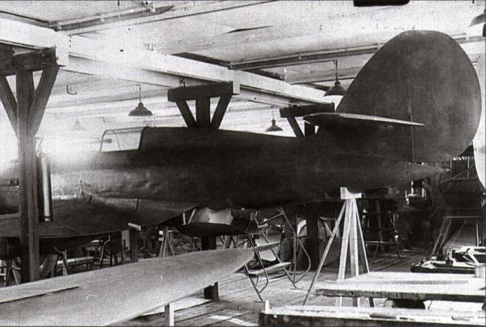
Model of the Grigorovich IP-2 during the construction process at the beginning of 1936
Grigorovich designed the IP-2 / DG-54 (Russian: Григорович ИП-2 (ДГ-54)) fighter in the winter of 1935-1936. The IP-2 appeared as a modification of the IP-1 gunship fighter and as main differences it had slightly increased dimensions and a 760 hp Hispano-Suiza 12Ybrs engine. The manufacturing name of the model was DG-54 and in some literature it has been called PI-2 by the acronym P uchechni I sterbitiel or Gunship fighter.
The IP-2 fighter was designed as a single-seater monoplane with a low cantilever wing. In plan view it was similar to the British Supermarine Spitfire.
The IP-2 kept the elliptical wing introduced in the IP-1 and built according to the “Grigorovich wing without stringers” formula. The main difference is that in the case of the IP-2, the builders were forced to install an inverted gull-type wing in order to raise the nose of the device from the ground in the presence of a larger diameter propeller.
The fuselage in this case maintained a construction similar to that of the IP-1, but it featured an elongated nose in order to accommodate the Klimov M-100A engine, a licensed version of the 860 hp Hispano-Suiza 12Ycrs. The tailplanes, elliptical in shape, presented in this version medium implantation and cantilever.
The landing gear maintained the retracting system with the wheels semi-inserted in specially designed fairings and installed at the wing angle change point.
Another new detail in the IP-2 was the closed cockpit for the pilot. This fighter incorporated a powerful armament consisting of a 20 mm ShVAK cannon located in the V of the engine and 4 ShKAS 7.62 mm machine guns located in the wings. This could be increased up to 10 machine guns in the ground attack version. Under the wing, supports were provided to carry up to 40 kg of bombs.
During the first half of 1936 a full-size mock-up was built at Factory No.1 “Aviajim” followed by approval to build an experimental prototype.
The project was completed and in the first half of 1936 a set of parts and components had already been produced, but once again Grigorovich was affected by the restructuring of the Soviet aircraft industry. On May 11, 1936, the Labor and Defense Council (STO) decreed the specialization of aeronautical factories and the linking of builders with the serial production of their models.
In the summer of 1936 Grigorovich’s OKB was closed and he transferred to GUAP as head of the naval department. His group, made up of 25-30 people, was sent to the TsAGI Experimental Construction Factory (ZOK). All the unfinished projects ended up there, including the IP-2 fighter. The ZOK had been intended to specialize in the development of scout aircraft, so all documentation and items produced were sent to Kharkiv Factory No.135, where the IP-1 was produced. A year and a half later, when the production program was redefined for 1936 –1937 the IP-2 was excluded.
Powerplant: 1 × 860 hp Klimov M-100A Wingspan: 11.00m Wing area: 20.60 m² Length: 8.06m Height: 3.27m Empty weight: 1430 kg Take off weight: 1952kg Wing loading: 94.75 kg/m² Power load: 2.27 kg/hp Accommodation: 1
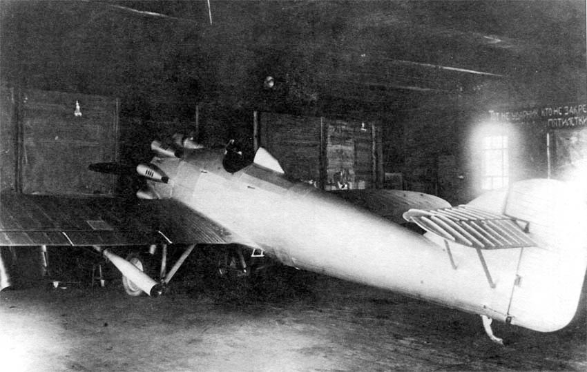
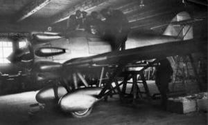
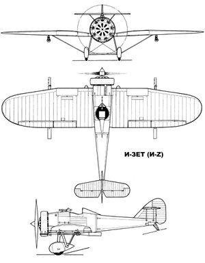
first prototype of the IZ fighter in the workshop of Factory No.39.
At the end of the 1920s work related to the development of a new type of barrel known as a dynamoreactive barrel (DRP) and characterized by the absence of recoil.
Great attention was devoted to the development of the 76.2 mm aviation guns. The main reason for this decision was the need to increase the firepower of the fighters, whose machine guns proved ineffective against the new all-metal bombers.
The first gun of this type, called APK-1 after the acronym for Avtomaticheskaya Pushka Kurchevskovo or Kurchevski ‘s Automatic Cannon, began tests on July 26, 1929. It became clear that the use of APK guns required the design of new types of aircraft with great structural reinforcement.
The task of designing this new type of aircraft was assigned in parallel to the TsAGI led by AN Tupolev and the TsKB under the direction of the OGPU, headed (unofficially) by DP Grigorovich as technical director.
Grigorovich had been under arrest since September 1928 and was under the supervision of the OGPU. After the collective of prisoners under his leadership succeeded in developing the excellent I-5 fighter in the spring of 1930, Grigorovich, though still under arrest, was appointed chief consultant to the TsKB. Prison conditions for him were improved, even allowing him to travel with his family on vacation to Yalta (with the necessary company of OGPU staff). Returning from the south, Grigorovich was asked to develop a fighter aircraft with three-inch barrels.Kurchevsky.
The aeronautical development system applied in the TsKB-39 did not conceive the existence of a main constructor. The designs were developed by brigades directed by a specialist and from the initial conception, different departments were in charge of carrying out the work related to their specialty. For this reason, the models developed in the TsKB during this period are generally not referenced to a specific author (generally in the literature they are named TsKB and the particular name of the model). However, in the case of the IZ fighter, the same is not the case. Despite being built within the structure of the TsKB, the task was so secret and a priority that Grigorovich received the approval to form a small group under his direction, which was to be in charge of all the development of the model.
The new task force of the Grigorovich began work in one of the hangars of Factory No.39. Among its members were: AN Sidielnikov, VL Korvin-Kerber, AN Nadashkievich, Ye. I. Mayiranov, VD Yarovidski, G. Ye. Chupiloko and S. N. Shishkin. In general, this group had stood out during the development of the I-5 fighter , so many of the construction elements of the new fighter would be designed under this influence.
In relation to the origin of the name for the new fighter there are several versions. The first version establishes that due to the secrecy in relation to the project, it was decided to name it using the Latin letter Z (something unconventional since letters of the Cyrillic alphabet were generally used for these cases). In this way the name of the fighter combines the Cyrillic letter И (corresponding to the I and acronym for Istrebitiel or hunting) with the Latin letter Z.
Other sources state that since the fighter was developed in hangar No.7 of Factory No.39 its initial name was I-7, but due to the appearance of another model I-7 mass-produced in Factory No.1 from Moscow (licensed version of the Heinkel HD-37), Grigorovich suggested adding a line at the bottom of the number so as not to have to redo all the documentation and thus the 7 became Z (Russian: Григорович И-Z – ЦКБ-7).
Which of these versions is the real one is difficult to establish. In period documents the fighter is referenced as TsKB7, TsKB-7, Z(N-7). Only a couple of years later, when the model had already been approved, the term И-Z began to be used in the documentation, but due to the fact that most typewriters in the USSR lacked the possibility of writing Latin letters generally everything was written in Russian as И-ЗЕТ (I-ZET).
By the spring of 1931 Grigorovich’s work had attracted widespread attention. Members of the GPU leadership and later from the Kremlin would soon begin visiting the TsKB. The TsKB would be visited by Molotov, Ordzhonikidze, Andreyev, Voroshilov. As a result of this interest, most of the prisoners would soon be released.
In May 1931 the newspaper “Pravda” would publish “granting amnesty to the builders listed below, previously accused and sentenced by the OGPU college to different sentences of a social nature and at the same time rewarding them. To the chief builder of experimental models Grigorovich, Dmitri Pavlovich, retracting his previous positions and proving after a year’s work of his sincerity – the recognition of the TsIK USSR and a cash prize of 10,000 rubles.”
The IZ fighter was designed as a single-seat, low-wing braced monoplane. The fuselage featured metal construction. The entire front and center fuselage was made of a skeleton of welded chrome-molybdenum steel tubes. In general, this entire forward section presented little difference from that of the I-5 fighter. The tail section was all new, semi-monocoque construction and attached to the front at four points.
The structure of the tail section was made up of 11 elliptical frames, of which the last four were integrated into the keel. The fuselage featured a duralumin coating.
The wing had a double spar structure and its fixing was reinforced o by a pair of steel supports with a drop-shaped section. The wing construction in the prototype was developed using stainless steel (Enerzh-7) joined by welding, but the production examples used wooden wing structure. The stringers had a box-like structure to which 22 plywood ribs were attached. The wing covering was made of fabric, except for the area where the cannons were fixed, where it was reinforced with aluminium.
The wing profile was Gettingen 436, but its thickness decreased in the area where it joined the fuselage. The centroplane had a rectangular shape, but the wing consoles, in order to reduce the inductive resistance, received an elliptical shape.
The tail unit was duralumin and heavily reinforced. The entire empennage skin, excluding the leading edge of the keel, was corrugated. The stabilizer was raised on the empennage in order to avoid the harmful effects of exhaust gases from the guns and was braced to the empennage by two parallel metal studs. Initially, the rudder had a fabric covering, which was soon replaced by a duralumin one.
The landing gear featured steel N-legs with rubber cushioning and a central axle linking the 750 x 125mm main wheels. Tensioning straps started from the undercarriage to the wing. In the tail a steerable skate with rubber cushioning.
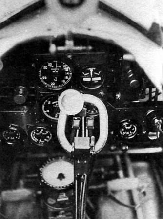
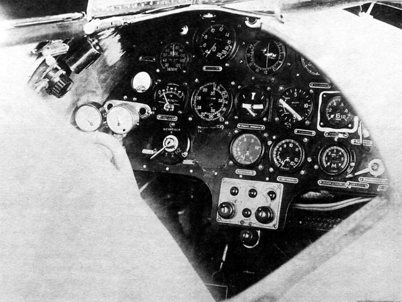
Instrument panel in the cockpit of the IZ fighter.
The power plant of the IZ consisted of the M-22 engine (version of the Gnôme-Rhône 9Aq, a licensed copy of the British Bristol Jupiter VI engine built in the USSR at Zaparozhie Factory No.29) and its installation it was virtually identical to that of the I-5 fighter, built by Polikarpov and Grigorovich some time before. The cylinder heads on the prototype featured individual fairings, which were replaced on production models by a Townend ring.
The pilot was located in an open cockpit, located behind the engine and lacking a windshield.
The armament consisted of a 7.62 mm PV-1 machine gun located in the fuselage, to the right and in front of the pilot, which was used as a sighting rifle for the cannons. This machine gun was fitted with a PUL-9 synchronization system to allow firing through the moving propeller. Under the wings were the two APK-4 or APK-4bis cannons.of 76.2mm. Its installation on the wing allowed firing without interference from the propeller. In the first IZ the guns were located in the inner area of insertion of the wing supports. Later the guns would be moved further out on the wing. Each barrel was equipped with a cylindrical magazine with 6 shells and a seventh already mounted on the gun and featured an automatic reloading system from the use of exhaust gases. 0.6 m cylinders designed as exhausts were located at the rear of the guns.
The IZ prototype was ready for the summer of 1931. The date of its first flight is not known with certainty, but it is known that it was made in this period by test pilot Benedict L. Buxgolts.
On July 6, 1931 Factory no.39 was visited by Stalin, who had previously been informed about the IZ fighter. Stalin not only checked the plane, but climbed into the cockpit and moved the flight controls. The main builder was not there at that time, so the presentation of the model was made by the head of the TsKB for the GPU Ye. S. Paufler.
YV Stalin in the cabin of the first IZ at Factory No.39 on July 6, 1939. On the wing (from left to right) engineer G. Ye. Chupilko, VM Molotov, K. Ye. Voroshilov, AN Rafaeliants and GPU Commissar Ye. S. Paufler.
During this visit Stalin was presented with other models developed at the TsKB such as the I-5 fighter in various variants, the TB-5 heavy bomber, the TSh-1 attack aircraft and TSh-2, modifications of the R-5. Stalin was favorably impressed. As a result, by the Aviation Union Order No.265 (VAO according to the acronym of B ciesoyuznoye A viatsionnoye O biedinienie) of August 27, 1931 the TsKB and the TsAGI would be united into a single organization (known generally as TsKB-TsAGI), under the direction of Paufler.
The IZ had been built in a hurry and this was reflected in its initial results. Grigorovich’s collective was forced to work on improving the model for a year. Despite successful tests, Kurchevski’s guns generated constant headaches. Building and testing the single-shot APK-1 cannons proved to be an extremely simple task compared with the development of autocannons capable of self-reloading and multiple shots.
The first modified IZ with new cowl and undercarriage
This situation began to worry some personalities. During a meeting at Factory No.39 held on March 2, 1932, the head of the VVS RKKA PI Baranov stated:
“The Z(N-7) aircraft has been built for almost a year, Factory No.39 presented it to the government in June-July 1931 and promised to improve it. where is the result?
Paufler replied that the plane had been ready for a long time, that 74 shots had been fired from the guns on the ground and 10-12 in the air, during which the exhaust of one of the APK guns had been damaged, but in general everything was fine. well and the factory was ready for series production. Kurchevski, who was present, complained that he was not allowed access to the plane to work.
It was established that the Z(N-7) would be used as an interceptor aircraft, designed to destroy enemy bombing forces in frontal encounters. Impact 3 kg shells with an initial velocity of 347 m/s were expected to make a formidable weapon. It was decided to submit the Z(N-7) for state testing on March 12.
After the first prototype, a second improved specimen would appear, which in some literature has been called I-Zbis. This model would fly for the first time in 1932.
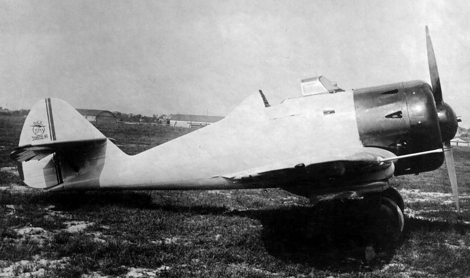
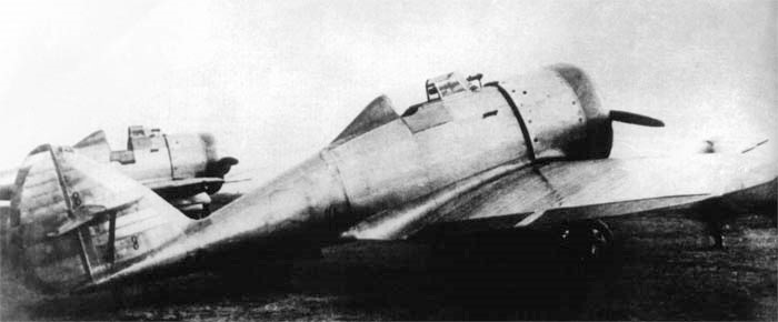
Serial Grigorovich IZ – wooden wing and Townend ring
No evidence has been found to show that the acceptance tests were carried out by the military, but on April 27, 1932, the director of Factory no.39 S. Margolin signed an agreement with the VVS Directorate to build 20 “Z” fighters with special weapons worth 77594 rubles per unit. Taking into account unforeseen expenses until September 1, 1933 (fixed delivery date) Factory No.39 would receive 2,398,909 rubles, which brought the actual price of each aircraft to 119,945 rubles.
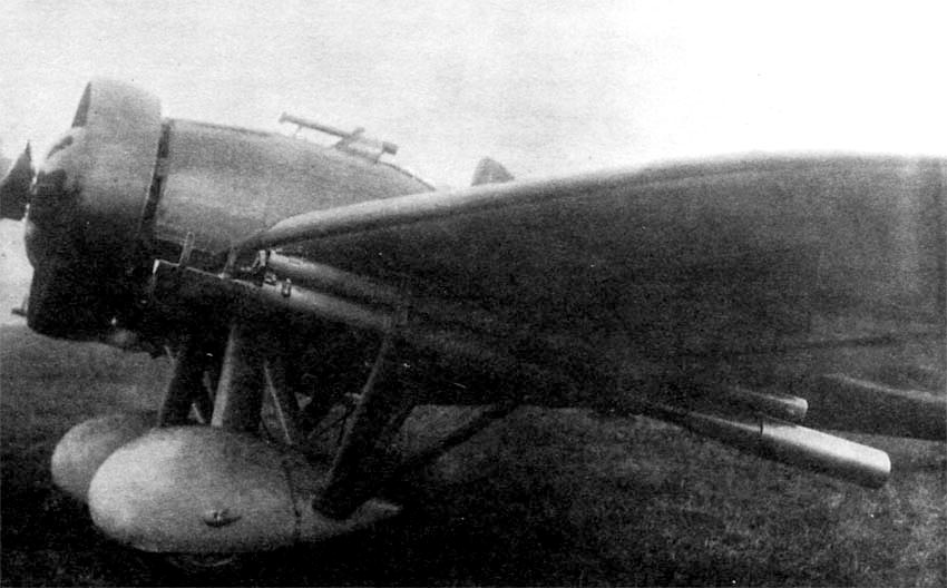
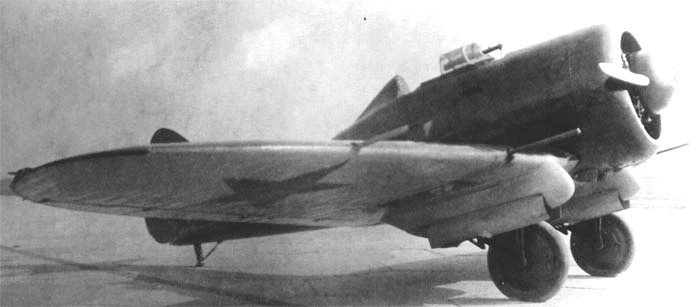
Series IZ with Townend cowl and APK-4 barrels.
This series were intended to carry out field tests and develop the tactics of use of the cannons and differed from the prototype by the use of a wooden wing and an M-22 engine faired with a Townend ring.
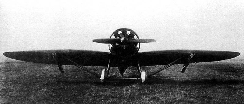
Front view of the series IZ fighter.
Between 1934 and 1935, another 50 aircraft were built at the Kharkov Factory No.135, but their flight characteristics and performance were not very good; moreover, the APK guns were also unconvincing. The maximum speed in these aircraft was about 40 km/h lower than that of the prototypes. Most of these ended up being used in different test programs.
One of the first serial specimens, the IZ with number 39009, was tested in February – March 1933 at the VVS polygon in Mónino. The tests were carried out by test pilot Yu Piontkovski.
Ground fire tests of the IZ number 39009 at the NII VVS (Shelkovo) in Feb – Mar 1933.
The aircraft carried a working cannon under the left wing and a mock-up of similar weight and dimensions under the right. For the development of ground tests in Shelkovo. This land had recently been handed over to the NII VVS and there were no buildings of any kind on it. There, a structure 5-6 meters high was prepared with an inclined ramp from which the shots were fired. During these tests, intended to check the resistance of the aircraft during the action of the gun, no problems were found.
From September 14 to October 1, 1933 in Shelkovo the tests of the IZ 39010 were carried out, armed with the APK-4 serial guns equipped with magazines for 6 projectiles (plus one directly located in the barrel).
The flights were carried out by M. Stselnikov and in total they lasted 16 hours and 20 minutes.
The results highlighted that 39010 was built quite similarly to the prototype and due to its dimensions and characteristics, no differences were observed.
The cockpit was comfortable and spacious. During takeoff the IZ lifted off the ground with ease and horizontal flight was performed with the stick fully free. Stability was good at all speeds and control was smooth and easy.
The data obtained for time of ascent to 5,000 m (14 minutes) and flight ceiling (7,000 m) were considered acceptable, but the maximum speed of 259 km/h and the range of 310 km were evaluated as poor. The main cause of these difficulties was defined as the inefficient landing gear and the great aerodynamic resistance of the APK guns.
The artillery armament passed the tests, but its shell capacity was considered too small. Kurchevski proposed to install a magazine with 10-14 shells in the wing, but this would not come to fruition.
As a conclusion, it was defined that the IZ fighter could be received into service with the RKKA VVS with the fulfillment of the following conditions: Raise top speed to 300 km/h Increase fuel capacity Raise the amount of shells to 20 units Install electrical equipment and radio Desire to increase the structural rigidity of the plane, because after 300 – 500 shots it was necessary to carry out a complex maintenance intervention on the aircraft. The VVS wanted to raise this number to 1,000 shots. The modified aircraft was to be ready by March 1, 1934.
The installation of the cannons added a significant number to the aircraft’s weight. The two APK-4 guns weighed about 150 kg, and the 14 ammunition – 55 kg. This meant 12% of the model’s takeoff weight. The APK-4 dynamoreactive cannons were installed in the wing of the aircraft with angles of 2 – 3º. All this part of the wing was coated with duralumin. This location contributed significantly to the poor performance due to the high aerodynamic resistance of the installation.
In April 1935, a special aviation group was created, consisting of a squadron of IZ fighters, one of R-5 reconnaissance aircraft for cone towing, and a TB-1 bomber. This unit was transferred to Yevpatoria in order to test the behavior of the gun in the air, its influence on the construction of the IZ fighter and the definition of its service time.
Test flights began on May 15, 1935. The tactics provided for firing in a dive, ascent or horizontal flight, both in individual salvos and in series.
It was found that after 100 to 150 shots the aircraft had to be inspected in depth as it generally suffered extensive damage to its structure and coating, making it necessary to replace the damaged elements and components. Fundamentally, the rivets, joints and coating suffered. It was also established that each cannon could withstand about 240 shots.
Cases are recorded of number 13534, which was capable of withstanding just over 340 shots without the need for repair. From the results of the tests it was considered that the period of active service of the IZ model should be defined by the scope of the figure of 400 shots.
In the development of multiple tests, most of the IZ specimens produced became unusable. At the beginning of 1936 the units received only a few copies. By that time the work on the DRP guns had practically been abandoned and the use of these fighters was out of date. For this reason the IZ did not get to operate in the designed roles.
The IZ was one of the aircraft used by VS Vaxmistrov in the development of his combined or ”Zvenó” aircraft. From the beginning of 1931 Vaxmistrov began work on the suspension of an IZ fighter under a Tupolev TB-3 bomber. In 1934 Vaxmistrov decided to develop a new version of the Zvenó by combining a TB-3 with two IZ fighters. this combination would be known as Zvenó-3 or 3-3.
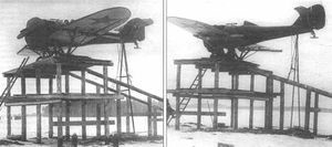
IZ with the trapeze used for the suspension in Vaxmistrov’s Zvenó.
In this combination the fighters were fixed on the ground by special supports to the wing of the bomber. Before release, these supports separated from the wing by 0.5 meters in order to avoid impacts of the empennage against the wing at the time of detachment.
The first flight of this combination was made in July 1934. The TB-3 bomber crew was led by PM Stefanovski and the IZ fighters included AV Korotkov and Grodz. During the release Korotkov’s fighter rose, breaking the bomber’s wing skin and getting stuck in it. An emergency landing was necessary. Luckily, at the time of landing, the plane broke free as a result of the impact with the ground. The fighter pilot was killed but the rest of the crew managed to save themselves. As a result the Zvenó-3 combination was abandoned.
Zvenó No.5 – Grigorovich IZ fighter and Tupolev TB-1 bomber.
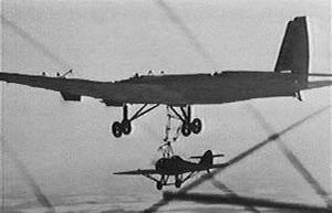
The next variant of use of the IZ fighter in combined aircraft was known as Zvenó-5 (3-5) and involved suspension of an IZ fighter under the TB-3 bomber once it was in the air. The mother plane released a kind of trapeze that was fixed to the DER-15 rear supports. The release of this structure was carried out by the on-board mechanic from its location and its subsequent retraction was carried out with the help of a crank.
The IZ fighter was also modified. In the upper part of the fuselage a fixing structure with a security system was installed. The wing consoles were also reinforced, since the section of the wing ribs 12 – 14 ended up resting on the bomber wheels once the trapeze was retracted. The other support point was at the top, behind the cockpit.
Testing of the Zvenó-5 began on March 15, 1935. In this case, the IZ was piloted by VA Stepanchonok, while PM Stefanovski was once again at the controls of the TB-3. Initially, training flights were carried out consisting of placing the fighter behind the bomber, equalizing their speeds at about 140 km/h and then making approaches and separations to a percale tape fixed to the bomber. Until March 21, 25 trainings of this type were carried out.
The world’s first capture of one aircraft in flight by another took place on March 23, 1935. After fixation the IZ was elevated. The Zvenó dropped to a height of 500 meters and flew over the aerodrome where a VVS commission sent to supervise the test was located. After recovering the 1200 meters of height, the separation took place, again without problem. Until March 29, 5 flights like this were carried out with capture and release of the IZ fighter in the air.
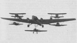
The Aviamatka PVO in flight with its 5 fighters. At the bottom hangs the Grigorovich IZ.
By the fall of 1935 Vaxmistrov prepared for tests a new combined system known as Zvenó TB-3 4M-17 + 2 I-5 + 2 I-16 + IZ. Vaxmistrov himself named this creation Zvenó Aviamatka PVO (AM). On the ground under the wing of the TB-3 two I-16 fighters were fixed and on the wing the two I-5 fighters. The last member, the IZ fighter, was fixed once the Zvenó was in the air.
During the tests the TB-3 was flown by PM Stefanovski, the I-5s by AI Nikashin and SL Suprún, the I-16s by TT Altynov and KK Budakov and the IZ VA Stepanchonok.
The experiments demonstrated the feasibility of using the chain consisting of one bomber and five fighters. Never before or since in the world has anything like it been tried. The tests were carried out jointly with the Moscow Factory No.22, in charge of carrying out the modifications to the fighters and the mother plane.
The conclusions of the tests determined that the Zvenó with TB-3 4M-17 + 2 I-5 + 2 I-16 + ZET can be effectively used in RKKA units. However, the final conclusions were different. It was considered that the presence of the I-5 fighters on the wings and the IZ under the fuselage limited the possibilities of the TB-3 bomber, so it was preferred to develop a variant with only two I-16 fighters in attack version under the name Zvenó SPB and would be used successfully during World War II.
IZ Powerplant: One 480-hp M-22 radial Wingspan: 11.50m Wing area: 19.5 m² Length: 7.65m Empty weight: 1180 kg Normal takeoff weight: 1648 kg Wing loading: 84.5 kg/ m² Power Load: 3.4kg/hp Fuel + oil capacity: 180 kg Maximum speed at sea level: 258 km/h Top speed at 5,000m: 239km/h Cruising speed: 212km/h Landing speed: 100km/h Practical range: 600 km Endurance: 2.5h Maximum rate of climb: 358/min Climb time to 5000 m: 14 min Practical ceiling: 7000 m Landing run: 180m Take-off run: 110m Armament: Two 76.2mm Kurchevski APK-4 cannon with 14 rounds / one 7.62mm V-1 machine gun Accommodation: 1
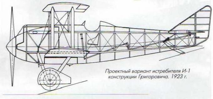
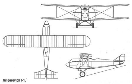
The Grigorovich I-1 (Russian: Григорович И-1) was designed by DP Grigorovich as a fighter. Knowing that NN Polikarpov was designing a new fighter, Grigorovich decided at all costs to take on a similar task.
The general design was carried out by Grigorovich with the help of VV Kalinin. Engineer AA Krylov was in charge of the aerodynamic calculations. The concept design was conceived in just three days and submitted to the Department of Aviation almost in parallel with that of NN Polikarpov’s fighter of the same name.
The I-1 fighter was a single-seat biplane built basically of wood covered with fabric. The fuselage with a wooden structure was characterized by its constructive simplicity. The sides were straight, with some curvature at the top and bottom. At the bow and with a large aerodynamic hub covering the propeller was the 400 hp M-5 water-cooled engine (licensed copy of the North American Liberty L-12), completely covered by an aerodynamic aluminum hood. The original cooling system included a circular-type Lamblin radiator located between the main landing gear. Problems with motor heating motivated several modifications of this radiator. The entire rear region of the fuselage was covered in fabric.
The wing, of a single section, had planes of equal span linked by means of parallel interplane uprights made of wood and 12 mm bracing straps. The selected airfoil was the Gettingen 436. The upper plane had shutter-type ailerons.
The tail was monoplane, of conventional configuration. The construction was of wood covered with fabric. The horizontal, cantilever-type planes featured large-area elevators. The rudder was attached to a small triangular keel. The landing gear was of the conventional type, with a tail skid and fixed landing gear, linked by a bar.
The pilot was located in an open cockpit located behind the wing trailing edge. The control system was rigid.
The armament designed two 7.62 mm machine guns, although there is no evidence that they were ever installed in the prototype.
The construction of the Grigorovich I-1 was developed within the experimental construction plan of the GAZ No.1. The biplane was completed in September 1923 and on October 5, after receiving the approval of the Scientific Committee of the VVS Directorate (UVVS), it was approved to begin flight tests.
It is noteworthy, that despite Grigorovich’s efforts, NN Polikarpov’s IL-400 (Fighter with Liberty 400 hp) or I-1 monoplane would be ready some time before, but unsuccessful attempts to make it fly on August 15 of 1923 definitively reaffirmed Grigorovich’s position.
The first flight of the I-1 took place on October 30, 1923. The Grigorovich I-1 managed to take off without difficulty and during the test flights it was possible to set a maximum speed of 238 – 240 km/h with climb times to 2,000 meters in 5 minutes and to 5,000 meters in 19 minutes. This made it the fastest aircraft on the Moscow airfield. It was defined that the I-1 was the first successful attempt to create a fighter since the end of the war.
The general opinion was that the plane was stable in the air and responded correctly to the controls. As a problem, the presence of overheating in the engine was highlighted, despite the modification on several occasions of the shape of the radiator.
Despite this, the I-1 was considered only as an experimental model and from the very beginning of the tests Grigorovich and his team began to design the improvements, in parallel with the modifications demanded by the flight tests. All these changes and improvements delayed the delivery of the plane for the development of tests at the NOA (acronym for Nauchno Opytni Aerodrom or Scientific Experimental Aerodrome), so that at the time of its appearance there, the plane had been surpassed by the design improved I-2. This new design seemed to present a better disposition for military use.
I-1 Engine: 400 hp M-5 Wingspan: 10.80m (9.0m) Wing area: 26.80 m² Length: 7.32m Empty weight: 1188 kg Speed at sea level: 238 – 240 km/h Landing speed: 95 km/h Range: 600 km Endurance: 2 h30 min Practical ceiling: 6000m Time to 2000m: 5min Time to 3000m: 8min Time to 5000m: 19min Accommodation: 1 Armament: Two 7.62mm machine guns
The IP-3 fighter, which received the manufacturing name DG-53 (Russian: Григорович ИП-3 (ДГ-53)), basically differed from the DG-52 (IP-1) due to its smaller dimensions, its reduced surfaces and its lower flight weight. It seems that with the IP-3 Grigorovich tried to obtain a fighter for close combat armed with machine guns, but for some reason he drifted towards a utility model equipped with Kurchevski ‘s dynamoreactive cannons. In this case, the cannons were simply smaller in terms of caliber, weight and dimensions.
The IP-3 fighter was designed to use the 37 mm APK-11 recoilless automatic cannon, proposed by Kurchevski in 1932. These cannons stood out for their magazine feeding, which allowed the number of projectiles per gun to be increased to 25. Up to 12 projectiles were placed in two magazines and the last one was placed directly in the gun when preparing it. The weight of the APK-11 with the magazines reached 39.1 kg. The explosive projectile weighed between 475 and 500 grams and was ejected from the barrel at a speed of 438-475 m/s. The reloading of the barrel after each shot was done automatically using compressed air located in a 5-liter tank.
In addition to its smaller dimensions, the IP-3 was easily differentiated by having individual exhaust pipes that came out of holes in the hood and the introduction of cantilever wing planes. A novelty in this model was the installation of landing flaps. The Shvetsov M-25 radial engine, developed on the North American Wright Cyclone, remained as the power plant.
This fighter was designed to carry two 37mm Kurchevski APK-11 cannons as well as two light machine guns. Unfortunately, at the time of finishing its construction, the APK-11 guns were not yet available. By the end of 1934 it was decided that the APK-11 guns were not ready and for their acceptance it would be necessary to modify them.
On July 2, 1935 the head of the OKB of Factory No.1 Aviajim DP Grigorovich informed the head of the GUAP GN Korolyov about the completion of work on the prototype. In his letter he wrote: “The IP-3 aircraft with Wright Cyclone is ready for factory tests and has been received by the LIS of Factory No.1 to carry out the tests. I request your approval to start them.”
Factory tests were started in July 1935. Apparently the hope of receiving the APK-11 guns remained latent and the definition of the future of the plane depended on these works.
With the decision to suspend work on the dynamoreactive guns, the interest in the IP-3 disappeared and the development of the model was not continued. In later documents appears the instruction to delete the IP-3 Shvetsov M-25 of Factory No.1 from the construction plan for 1937.
A second prototype known as the IP-4 or DG-53bis and designed to carry two ShVAK guns instead of the Kurchevski ones, remained in the project phase.
Kurchevsky continued to improve his 37mm guns and even managed to get it approved for mass production, but this weapon never found practical application.
IP-3 Engine: Shvetsov M-25, 700 hp Wingspan: 9.60m Length: 7.08m Wing area: 16.36 m² Normal takeoff weight: 1548 kg Maximum speed at sea level: 382 km/h Maximum speed at height: 435 km/h Cruising speed: 298km/h Practical range: 830 km Practical ceiling: 8800 m Armament: Two 37mm Kurchevski APK-11 cannons, 25 rds & two 7.62mm ShKAS machine guns. Accommodation: 1
Grigorovich IP-1 with ShVAK cannons and machine guns in the wings.
A proposal arose to use new-type cannons in airplanes, in which the recoil was compensated by the reactive force of the gases expelled during firing, for which they were known as dynamoreactive cannons (DRP). These guns were lighter than normal guns of a similar caliber.
The development theory of dynamoreactive guns was developed in the late 1920s by professor and later academician BS Stiechkin. The engineer LV Kurchevski was in charge of materializing these ideas. The guns designed by him were named APK after Avtomaticheskaya Puchka Kurchevskovo or Kurchevski Automated Guns and would be used for the first time in the IZ fighter developed by Grigorovich.
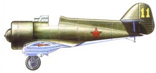
In 1934 D. P. Grigorovich prepared a new fighter armed with APK cannons, which received the factory name DG-52 and was known by the military as IP-1 (acronym for Istrebitiel Puchechni – Gunfighter) (Russian: Григорович ИП-1 (ДГ-52)).
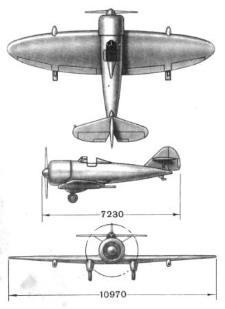
Structurally, the IP-1 was designed as a low-wing cantilever monoplane with all-metal construction. The fuselage terminated in a large-area empennage with the planes set high and braced by struts. The fuselage skin was made with sheets of 1.0 – 1.5 mm. The central wing occupied 55% of the entire span to locate the cannons outside the propeller arc.
The elliptical-shaped wing was designed to achieve the lowest inductive resistance. The wing construction was made up of tubular chrome-molybdenum steel stringers with skeletal ribs made up of rolled profiles with stringers supporting the coating. This wing would later be known as the “Grigorovich Stringless Wing”. The wing covering, with sheets of 0.6 – 0.8 mm, was fixed to the edges of the stringers by means of additional profiles and to the edges of the ribs. The ailerons and landing flaps were designed as shutter type.
The tail was totally metal, but in the production copies the rudders were covered with fabric.
Originally a retractable type landing gear was selected with the ability to carry wheels in the summer and skis for the winter. The undercarriage retracted backwards, leaving the skis inserted in fairings in the wing. This solution, used for the first time in the USSR, reduced aerodynamic resistance to such an extent that the model could maintain performance throughout the year. The landing gear had oleo-pneumatic suspendion and the retraction system had a hydraulic drive. The prototype’s tail skid lacked retraction, but on production examples it would be replaced by a fixed wheel.
The power plant selected was the 640 hp Wright Cyclone SGR-1820 F-3 covered by a long NACA hood. The propeller had metal construction and ground adjustable pitch.
The pilot was accommodated in an open cockpit with a faired headrest in the fuselage.
The armament was similar to that of the IZ fighter, with two APK-4 dynamoreactive recoilless cannons under the wings capable of firing 5 rounds, but instead of the PV-1 machine gun a more effective ShKAS were installed. These machine guns were to serve as aiming rifles for the main recoilless guns.
Grigorovich IP-1 fighter with its APK-4 cannons under the wing midplane.
The state tests of the IP-1 fighter were developed between January and March 1935. The fighter was characterized by high speed and good manoeuvrability, with a turn time of 14-15 seconds. The climb was poor due to the great weight of the cannons.
The military gave an excellent evaluation of the model, highlighting the high speed, the good manoeuvrability and stability in flight, the simplicity of piloting, and the good visibility from the cabin. The great stability of the dive was also highlighted.
The tests showed that the fighter had reservations and problems appeared. Among them, the weakness of the engine hood, the overheating of the oil, difficulties with the control of the plane at the time of departure or retraction of the landing gear, the inconvenience of using the machine gun and the lack of rigidity in the fixing of the APK cannons, among others.
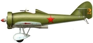
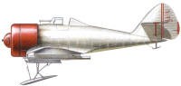
Grigorovich IP-1 prototype color scheme
After the tests carried out between August and September 1935, other defects appeared, such as weakness in the fuselage coating and low effectiveness of the ailerons. It is noteworthy that none of these problems was serious and all could be solved with a certain amount of work, so they did not overshadow the potential of the model. The design collective kept improving the IP-1 until 1936.
The head of the VVS Ya. I. Alksnis demanded that the RKKA VVS Directorate submit its requests to increase the request for IP-1 fighters at the cost of reducing the requests for other fighters.
The IP-1 went into production at Kharkiv Aviation Factory No. 135, where a metal aircraft was being built for the first time. In parallel, modifications and improvements began, which were introduced directly into the production process. Early examples were armed with two APK-4s and two ShKAS machine guns.
first production versions with a tapered fuselage
At that time the VVS’s perception of dynamoreactive guns had changed. The results of Kurchevski ‘s APK guns were not what was expected and, on the other hand, conventional guns had already appeared, of smaller caliber, but with greater speed. The Directorate of Special Works (USR), led by LV Kurchevski, was dissolved in February 1936 and this builder would soon be a victim of the repressive wave of those years.
Already in the summer of 1935 Grigorovich had received a request to develop a modification of the IP-1 with 20-mm cannon and machine guns. In January 1937 the first example with this configuration, with factory number 034, was ready and successfully passed the factory tests. Production examples were fitted with two 20mm ShVAK cannons installed in the midplane and the machine gun armament was increased to six 7.62mm ShKAS machine guns (two under each wing console and one in the midplane). The Shvetsov M-25, a license-produced version of the Wright Cyclone F-3, was selected as the powerplant.
Between 1936 and 1937, up to the time production closed at Factory No.135, some 90 IP-1s were built.
These changes brought about a backward movement of the centre of gravity. During the spin tests, carried out at the NII VVS by PM Stefanovski, it was found that the model had problems.
Already at the stage of state tests in 1935, on one of the flights, the plane entered a flat spin from which it was difficult to get out, losing about 800 meters in height in the attempt. At that time it was considered a casual situation, but now, with the changes, the defect was showing up again.
Flight tests were planned to study the phenomenon. During the flight the test pilot AI Nikashin tried all possible manoeuvres, but it was impossible for him to get the IP-1 out of the flat spin and at the last moment he abandoned it by parachuting.
It was decided to begin a research process to improve the aircraft’s behavior in a spin. TsAGI participated in this process. The specialists of this institution came to propose a special parachute located in the tail section to facilitate the exit of the spin, but this solution was finally discarded. Professor AN Zhuravchenko proposed to install a long fin from the headrest to the vertical keel, which should improve directional stability. With these changes the plane was able to get out of any type of spin without difficulty.
IP-1 with new keel installed
A large part of the 90 examples produced ended up being delivered to the 43rd Aviation Brigade. RKKA VVSs used the IP-1 until 1939, when it began to be replaced by the Polikarpov I-16. From there the traces of the IP-1 disappear. The final destination of the withdrawn examples is unknown.
In November 1939 at the NII VVS the flight tests of the IP-1Sh model with a Shvetsov M-25 engine and modified by the institute’s specialists as an armoured attack aircraft were carried out. The modifications were made on a serial IP-1 model produced by the Kharkiv Factory No.135 in 1935.
The model featured armament similar to that of later versions of the fighter, consisting of two 20mm ShVAK cannons located in the midplane and six 7.62mm ShKAS machine guns. The “P” type armor consisted of 6 – 6.5 mm cement plates capable of withstanding impacts from 7.62 mm bullets from distances of 125 m and at angles of up to 35 degrees. This armour covered the vital points of the construction. The fuel tanks were protected by two armour plates weighing 72.8 kg.
The pilot was defended from shots from behind by an 18.5 kg armour plate and on the sides by two 12.6 kg vertical side plates. Frontal impacts were to be covered by the engine. In total all the armour added a weight of 125 kg.
The takeoff weight of this version reached 1,940 kg, so the maximum speed decreased to only 320 km/h at sea level and 343 km/h at 2,000 meters.
In the report of the conclusions of the tests, it was reflected that due to the poor flight performance, the construction difficulties and the appearance of associated difficulties (vibrations in flight and new problems with spin entry), the model lacked prospects for growth.
In order to study the effectiveness of this armour, it was decided to transfer the model to the NII-48 to study the resistance to the impact of different types of weapons.
The tactical specialists of the VVS planned to use the IP-1Sh fighters in chains or brigades, attacking the enemy in dive encounter contacts from distances of 1000 – 1500 from the target.
It was considered that the fighter would be basically intended for attacking ground targets located in a radius of action of 200-350 km or as part of Vaxmistrov ‘s Zvenó combined structures, in order to increase the range of actions.
The IP-1 was Grigorovich ‘s last aircraft to be mass-produced. In 1927 he became seriously ill and the following year died.
IP-1 Powerplant: 1 × 710 hp Shvietsov М-25 Wingspan: 10.97m Wing area: 19.98 m² Length: 7.23m Empty weight: 1200kg Normal takeoff weight: 1880 kg Maximum speed at sea level: 343 km/h Maximum speed at 3000 m: 410 km/h Cruising speed: 298km/h Practical range: 1000 km Maximum ascent speed: 574 m/min Practical ceiling: 7700 m Climb to 1000 m: 1 min 19 s Armament: Two dynamoreactive 76.2 mm Kurchevski APK-4 cannon – 10-14 shells / one 7.62 mm ShKAS machine gun. Accommodation: 1
IP-1 fighter in its original version with APK-4 cannon