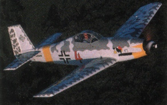
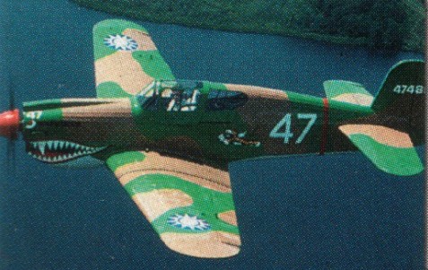
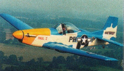
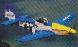
A 75% scale ultralight P-51 Mustang that qualifies as an LSA. The entire 5151 kit is designed for the inexperienced builder and is estimated to be completed in 400-500 hours. Almost all parts are pre-cut to exact dimensions, grooved, shaped and even tapered to ensure a perfect fit. The gussets and stringer attach pieces used in large quantity in the airframe are die cut like in a good model aircraft kit. The canopy and metal parts are also pre cut and those “difficult to make” parts are even preformed, predrilled and ready to assemble. All hardware comes separately packed and labelled for each section of the aircraft to avoid loss or confusion where parts go. The airframe kit includes everything to build the aircraft less engine, instruments and paint. Covering material and fabric glue, prop, tyres etc., and the enormous 18 inch custom spinner is also included in the airframe kit. Although the ROTAX 582LC is the recommend engine, there are several engine options including a 4 cyl., in-line 4-stroke engine available.
The construction of the 5151 Mustang consists more of an assembly than actually building, since all parts are highly prefabricated. Much of the assembly is of geodetic construction which, while it looks “fussy” it is actually a simple technique producing an exceptionally strong airframe for the structure’s weight. The fuselage consists of a conventional simple box-type construction which is transformed by formers and stringers into the shape of a P-51. The heart of the 5151 is the massive 10 x 12 inch centre section box spar which takes the optional wing tanks and the retractable or fixed landing gear, which ever the builder desires. The outer box spar i.e. wing panels attach to the centre section and are removable for storage or trailer, which leaves a foot wide structure on the landing gear for easy handling. Once the spar is assembled, the wing ribs simply attach to the spar and no jigs are needed since the aircraft is designed to be built on a flat bench. Also a remarkable feature is the technique used by the designer to virtually eliminate building errors in those critical components such as washout, taper etc., since the wing is tapered and all 12 wing ribs are different.
All tail surfaces are also built conventionally and consist simply of a leading edge spar, pre-cut trailing edge, ribs and geodetic bracing. The ribs are built over full-size drawings and are also built on the workbench, just as the entire rudder, elevators and vertical stabilizer. The retractable landing gear and also the fixed version is made of 4130N 2 inch chromolly tubing and comes tack welded.
The 5151RG has retractable undercarriage.
5151-RG
By 2014, the covering no longer came as part of the kit (available separately though), and only the Rotax 582 engine was offered. Ribs are solid wood – already cut to proper airfoil shape; simply require cap strips upper and lower.
5151 Engine: Rotax 503, 50 hp. Speed max: 95 mph. Cruise: 75 mph. Range: 325 sm. Stall: 28 mph. ROC: 700 fpm. Take-off dist: 150 ft. Landing dist: 250 ft. Service ceiling: 12,500 ft. Fuel cap: 5-13 USG. Weight empty: 513 lbs. Gross: 885 lbs. Height: 6 ft. Length: 22.9 ft. Wing span: 27.4 ft. Wing area: 130 sq.ft. Seats: 1. Landing gear: tail wheel.
5151 RG Engine: Rotax 582, 65 hp. Vne: 100 mph/ 89 kt. Cruise: 85 mph/ 79 kt. Range: 325 nm. Stall: 30 mph/27 kt. ROC: 1200 fpm. Take-off dist: 150 ft. Landing dist: 250 ft. Service ceiling: 12,500 ft. Fuel cap: 13 USG. Weight empty: 600 lbs. Gross: 885 lbs. Height: 6 ft. Length: 22.9 ft. Wing span: 27.4 ft. Wing area: 130 sq.ft. Seats: 1. Landing gear: tail wheel, retractable.
5151-RG Engine: Rotax 582, 64 hp Wing span: 8.4 m Wing area: 12.7 sq.m MAUW: 300 kg Empty weight: 203 kg Fuel capacity: 25 lt Max speed: 150 kph Cruise speed: 150 kph Minimum speed: 55 kph Climb rate: 4.2 m/s Certification: Vz Seats: 1 Fuel consumption: 13 lt/hr Kit price (1998): $7995
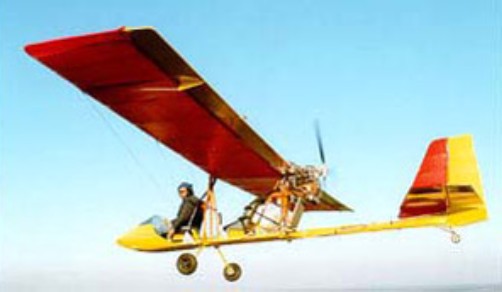
Produced by the Maxair Aircraft Corporation at the height of the ultralight boom, the original single-seat Drifter featured a 28-hp Rotax 277 engine. Its cable-braced wing and aluminum fuselage tube resulted in a rigid design that was soon expanded to include a two-seat trainer version and a short-wing, overpowered single-seat hot rod that was well outside ultralight limits. Some Drifters were equipped with monohull or dual floats.
Maxair declared bankruptcy in 1991, and the Drifter project was picked up by Phil Lockwood, who had worked for Maxair.
His company, Lockwood Aircraft, now kits the Super Drifter, an LSA, two-seat version powered by an 81-hp, four-stroke Rotax 912UL engine. With its standard 10-gallon tank, the Super Drifter claims a range of about 200 nautical miles at a cruise speed of about 60 knots—perfect for low-altitude, warm-weather exploring or short trips.
The two-seat Drifter and the similarly configured Air Cam has conventional controls and handling, and power is more than adequate. It’s worth noting that the rather short main landing gear legs and a long fuselage result in a nearly level three-point attitude on the ground. First-time front-seat pilots would benefit from climbing aboard, sitting awhile, and noting the angle between the Drifter’s small nose cone and the horizon. That’s the ideal landing attitude, and there is little ahead for a pitch reference.
Engine: Rotax 912, 80 hp HP range: 50-80 Length: 22 ft Wing span: 30 ft Wing area: 160 sq.ft Empty weight: 495 lb Gross weight: 1100 lb Fuel capacity: 10 USG Cruise: 70 mph Stall: 34 mph Range: 230 sm Rate of climb: 1000 fpm Takeoff dist: 200 ft Landing dist: 300 ft Landing gear: tailwheel
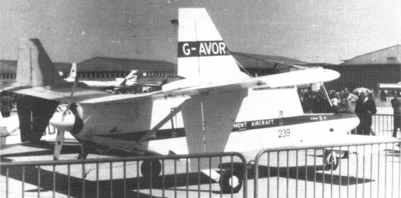
David Lockspeiser attempted to develop LDA (land development aircraft) general utility aircraft over two decades up to mid-1980s, with rear-mounted main wings and large canards, and rear-mounted engine with pusher propeller. A 70 percent-scale prototype flew 1971 as G-AVOR c/n LDA-01 and given PFA number 1346.
Construction was started at Shalford, UK, and the final assembly was done at Wisley. The two rear wing sections are interchangeable with each other and with the forward wing, which is mounted underneath the fuselage. The angular fuselage was capable of taking an underslung cargo pannier. A four unit undercarriage was fitted.
It was flown for the first time at Wisley on 24 August 1971 powered by a Continental C85-12. Initially it flew with a twin fin/rudder assembly but later a non-moving central fin was added.
In 1974, after a period of testing, the prototype was re-engined with a Lycoming O-320-D1A and given a conventional three unit undercarriage. The provision for the pannier was also removed. It appeared at the 1975 Paris Salon at Le Bourget France.
The intended full-size LDA-500 Boxer and larger LDA-1000 Boxer were designed.
Span: 29.00 ft Fore plane span: 13.00 ft Length: 22.06 ft
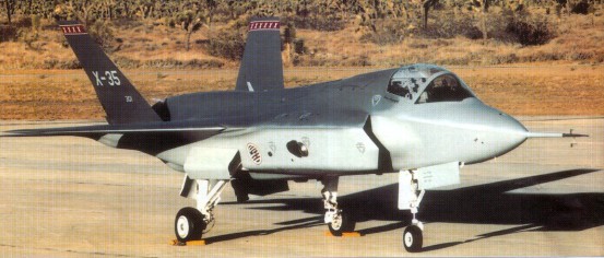
The X-35 was the Lockheed Martin Joint Strike Fighter (JSF) demonstrator, competing with the Boeing X-32. In November 1996 Boeing and Lockheed Martin were awarded contracts to build two Concept Demonstrator Aircraft (CDA)—one Conventional Take-Off and Landing (CTOL) version and one Short Take-Off and Vertical Landing (STOVL) version—each. The aircraft were not intended to be fighter prototypes, but rather to prove that the selected design concepts would work, hence the use of X-series designations.
Lockheed constructed two prototypes for the evaluation. The initial X-35A reflected the basic Air Force CTOL design, and was used for early flights before being modified into the STOVL version, designated X-35B. While Boeing proposed a direct lift STOVL design based on that used in the Harrier, Lockheed opted for a different approach in meeting the vertical flight requirements. Inspired by the Russian Yak-141, the X-35B incorporated a separate lift-fan that was shaft-driven by the F119 engine, allowing cooler exhaust temperatures during hover. While the Boeing design was more conventional, Lockheed argued that their strategy was better in the long term since it offered more room for growth as the aircraft evolves. The second airframe was the X-35C STOVL demonstrator for the Navy. This model featured an enlarged wing of greater span and area for larger fuel capacity as well as enlarged horizontal tails and flaperons for greater control effectiveness during low-speed carrier approaches. The X-35 was selected as the winner of the JSF competition on 26 October 2001.
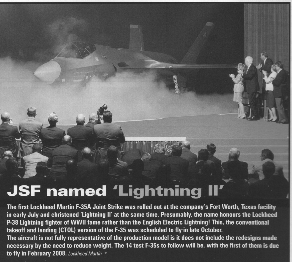
The production aircraft to be designated F-35. The System Development and Demonstration (SDD) phase of the F-35 JSF program started with the signing of the SDD contract in October 2001, and with the delivery of test aircraft scheduled to begin in 2008. During the SDD phase, 22 aircraft (14 flying test aircraft and 8 ground-test aircraft) were to be produced and tested. The JSF program is slated to produce a total of 3,002 aircraft for the United States and United Kingdom armed forces.
Lockheed Martin leads a development team including Northrop Grumman, BAE Systems, and Pratt & Whitney. Lockheed Martin brings in advanced technology experience, stealth technology and other technologies and experience which it has gained during F-22 research and development. Northrop Grumman offers tactical aircraft knowledge, stealth technology and carrier suitability. BAE System provides expertise and experience with short take off and vertical landing (STOVL) technology as well as advanced subcontract management. Pratt & Whitney is the builder of the engine which will power the JSF which is based on the F-119 turbojet from the F-22.
To forfill the demands of the main contractors three different variants are developed. All versions will have a common structure and have the same fuselage and internal weapons bay. They will all three be powered by a F-119 modified engine. All variants will carry the standard designation F-35.
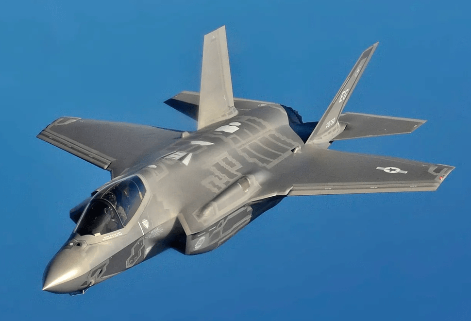
The F-35A is the standard variant with conventional take off and landing developed for the US Air Force, the biggest JSF customer. The F-35A will replace the F-16 and the A-10 aircraft currently operated by the USAF.
X-35B
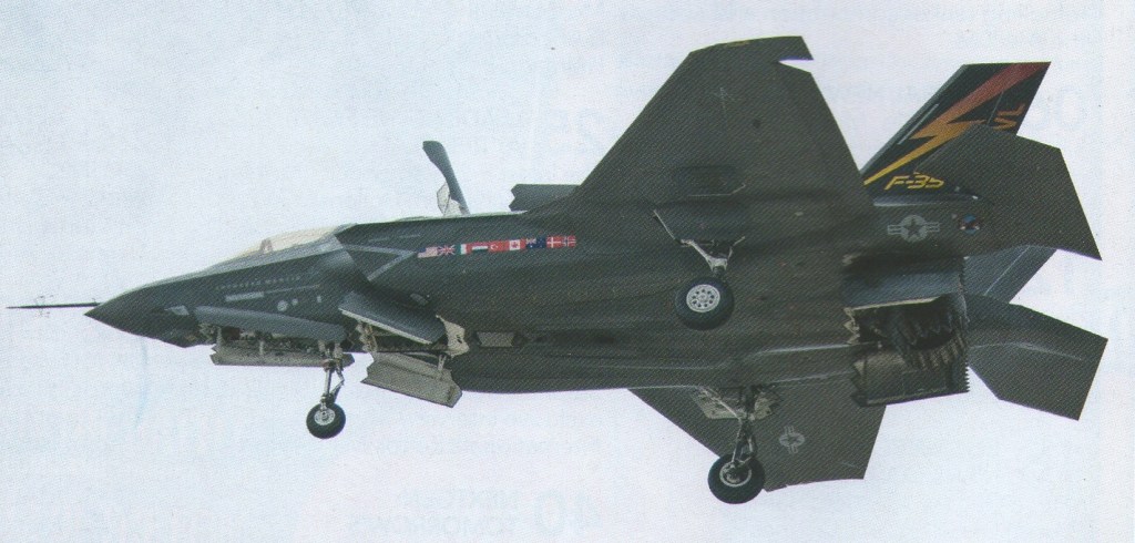
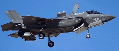
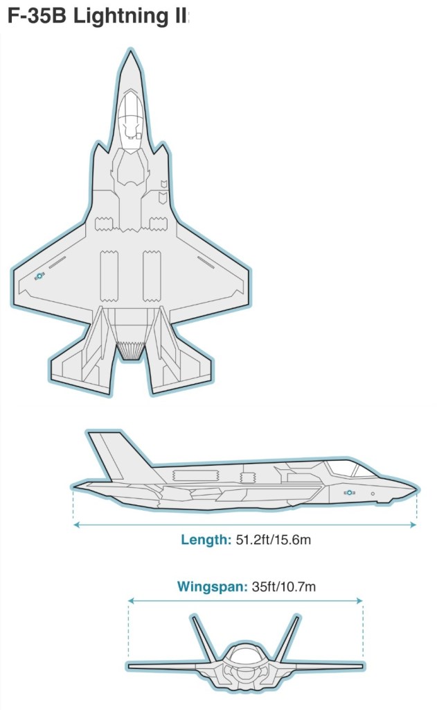
The F-35B is the STOVL variant of the JSF. The F-119 is modified using the experience of BAE Systems based on the Rolls-Royce Pegasus engine from the AV-8 Harrier. Unlike the Air Force variant the F-35B carries no internal gun and the air refuelling probe is located on the right side of the forward fuselage instead of receptacle on the top surface of the aircraft. The main customers for the F-35B will be the USMC to replace the F/A-18 Hornet ands the AV-8B Harrier IIs and the United Kingdom to replace the Royal Air Force/Royal Navy combined Harrier force of Sea Harriers and GR.7s.
The F-35C is a modified design which enables the JSF to operate from aircraft carriers using conventional carrier landings and catapult take off. The F-35C internal structure and landing gear have been strengthened to handle the loads associated with catapult launches and arrested carrier landings. It has a larger wing area than other JSF types with larger control surfaces for better low speed handling. Like the F-35B is has a refuelling probe instead of a receptacle. The US Navy will be the biggest customer of this variant. The F-35C will complement the US Navy fleet of F/A-18E/F fighters by replacing the F/A-18 A+ and C Hornet in service.
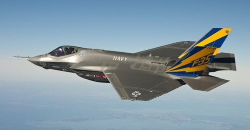
Lockheed Martin F-35B Lightning II BF-3 – the third example of the short takeoff/ vertical landing version – arrived at NAS Patuxent River, Maryland on February 17, 2010. It made its first flight on February 2 at Fort Worth, Texas and was taken from there to the naval air station by F-35 Test Pilot Jeff Knowles. Another two F-35Bs are due to join the three aircraft at Patuxent River for the flight test programme.
The F-35B was about to conduct its first vertical landing which would be a major milestone for the short take-off, vertical landing (STOVL) variant and work has started on the first F-35 lightning II for the UK.
The Lockheed Martin X-35C Joint Strike Fighter (JSF) Navy demonstrator completed medium-speed taxi testing Dec. 14 2000 at Palrndale, California, in preparation for first flight as early as Dec. 16. The aircraft, with a larger wing and control surfaces than the X-35A, will undergo about 20 hr. of flight test at Edwards AFB, before being flown to NAS Patuxent River, Md., for the continuation of demonstrations. Meanwhile, Boeing has completed structural mode interaction testing on the X-32B short takeoff and vertical landing demonstrator, expected to fly during the first quarter of 2001. The Boeing X-32A demonstrator completed government-required Navy demonstrations Dec. 2, 2000.
First flown on 24 October 2000, the JSF X-35A demonstrator aircraft completed a highly successful flight-test programme in August 2001, and the following October the US Government awarded its development contract to Lockheed Martin over the other contender, Boeing. The lift system uses a counter-rotating lift fan, located behind the cockpit and connected to the engine by a drive shaft, as a primary lifting force. The fan produces more than 18,000 lbs of cool thrust in hover flight, with an additional 18,000 lbs coming from the main engine’s vectored aft nozzle and wing roll-posts. The shaft driven Rolls-Royce lift fan amplifies engine thrust and reduces exhaust temperature and velocity during STOVL operations. First flown on 24 June 2001, in 2001 the X-35A, reconfigured as the STVOL X-35B, achieved its first vertical take-off, level supersonic flight, and vertical landing. The X-35C is to evaluate manoeuvering qualities, as a conventional carrier version and first flew on 16 December 2000. This version has larger wing and control surfaces and is stressed for catapult launches and arrested landings. This wing could also be applied to the B or A version.
By March 2010, it appeared that just five F-35s had flown: F-35A AA-01 on December 25, 2006. F-35B BF-0 1 on June 11, 2008. F-35B BF-02 on February 2, 2009 F-35A AF-01 on November 14,2009 F-35B BF-03 on February 2, 2010
The first F-35A has since been retired from flight duty. Two of the three F-35Bs were at Naval Air Station Patuxent River, Maryland, for preliminary STOVL evaluation tests.
The first pre-production F-35A flew on 15 December 2006, about three months behind schedule due to engine integration and ground testing delays.
F-35 Lightning II
As of 2014, 115 have been built at $106,000,000 each.
With over 1,000 aircraft delivered to 17 nations, including Australia, Israel, Japan, South Korea, and multiple NATO allies, and production plans exceeding 3,000 units, the F-35 represents the standardisation of fifth-generation technology across Western and allied air forces.
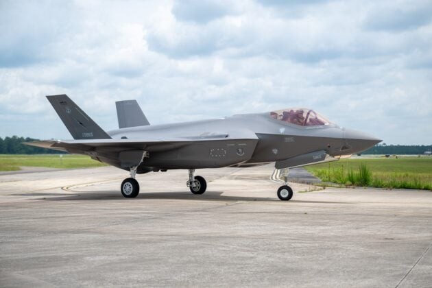
The U.S. Air Force’s 500th F-35A Lightning II fighter jet arrived at the Florida Air National Guard’s 125th Fighter Wing in Jacksonville on July 9, 2025.
500th USAF F-35A Lightning II
The aircraft is one of the first three F-35As permanently assigned to the wing, known as “the Thunder,” and features the unit’s legacy tail flash. By the end of 2024, Lockheed Martin had delivered a total of 1,102 aircraft. That figure included 797 F-35As built for the United States and allied air forces, along with 203 short takeoff and vertical landing F-35Bs built for the U.S. Marine Corps, the Royal Navy, the Royal Air Force, and the Italian Navy. The first examples for Japan’s Navy are also in production and delivery. According to F35.com, more than 1,215 F-35s of all variants have now been delivered worldwide, flown by over 3,000 pilots who have accumulated more than one million flight hours.
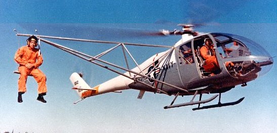
Lockheed began developing its rigid rotor concept with the CL-475 helicopter design in 1959 and the performance of the CL-475 encouraged Lockheed to continue development. Lockheed submitted the CL-475 to the Army as a candidate to replace the Bell OH-13 Sioux and Hiller OH-23 Raven observation helicopters. Lockheed also tested the commercial market waters without success. However, in February 1962, Lockheed’s Model 186, a new design based on the CL-475 rigid rotor, was selected as the winner for a joint Army-Navy program to evaluate the rigid rotor for high-speed flight capability.
Two four-seat, three-bladed XH-51As were ordered and built for the program. Powered by the 550 shp (410 kW) Pratt & Whitney Canada PT6B-9 turboshaft engine, XH-51A (serial number 61-51262) first flew on 2 November 1962. As flight testing progressed, the original three-bladed, rigid rotor system demonstrated instability at higher speed ranges. Lockheed engineers solved the problem by modifying the aircraft with a four-bladed rotor system. In 1963, the Army’s Technology Research and Evaluation Command (TRECOM) contracted with Lockheed to modify one of the XH-51 aircraft into a compound helicopter.
The second XH-51A (serial number 61-51263) was subsequently converted by adding wings with a span of 16.1 ft (4.9 m), and a 2,500 hp (1,864 kW) Pratt & Whitney J60-2 turbojet engine mounted on the left wing to increase performance. The XH-51A Compound first flew without powering up the turbojet on 21 September 1964, while tests were conducted for balance and handling. The aircraft’s first flight as a true compound helicopter took place on 10 April 1965, and on 29 November 1967 achieved a speed of 263 knots (302.6 mph, 486.9 km/h).
In June 1964, NASA ordered a five-seat, three-bladed variant, the XH-51N (NASA 531) as a helicopter test vehicle.
Lockheed built two demonstrator aircraft, designated the Lockheed Model 286, to market to the public (registration numbers N286L and N265LC). These aircraft had the five-seat configuration of the XH-51N with the four-bladed rotor system of the XH-51A. The Model 286 was certificated for civil operation by the FAA on 30 June 1966, but Lockheed never sold any aircraft. Lockheed used the aircraft for several years as executive transports, eventually sold them to a collector where they were destroyed by fire in 1988.
The two XH-51A examples (Serial Numbers 61-51262 and 61-51263) are stored at the United States Army Aviation Museum at Fort Rucker.
Variants:
186 Civil version of 286/XH-51 Rotor dia: 35 ft Length: 32 ft
286 / XH-51A four place, three-bladed rotor Engine: 1 × Pratt & Whitney Canada PT6B-9 turboshaft, 550 hp (410 kW) Length: 40 ft 9 in (12.40 m) Rotor diameter: 35 ft 0 in (10.67 m) Height: 8 ft 2½ in (2.50 m) Disc area: 962 ft² (89.4 m²) Empty weight: 2,790 lb (1,265 kg) Max takeoff weight: 4,100 lb (1,864 kg) Maximum speed: 151 knots (174 mph, 280 km/h) Cruise speed: 139 knots (160mph, 257 km/h) Range: 226 NM (260 mi, 418 km) Service ceiling: 16,000 ft (4,876 m) (hover ceiling (in ground effect)) Rate of climb: 2,000 ft/min (10 m/s) Disc loading: 4.26 lb/sq.ft (20.9 kg/sq.m) Power/mass: 0.27 hp/lb (0.44 kW/kg)
XH-51A Compound modified with a four-bladed rotor and stub wings and an auxiliary 2,900 hp Pratt & Whitney J60-2 engine. Rotor diameter: 31 ft 7 in Length: 31 ft 7 in
Model 286 five place civilian or military light helicopter offered for sale, none were sold.
Model 286 / XH-51N five place, three-bladed rotor modified for NASA test purposes.
The concept of the rigid rotor coupled to a gyroscope system was developed by an Advanced Concepts Group led by Irven Culver to seek significant improvements in performance, cost, reliability, and handling characteristics of helicopters. Following testing of a small radio-controlled vehicle – with a 1.52m diameter, two blade, hingeless rotor driven by a McCoy 60 model aeroplane engine – the small design team undertook in July 1959 to design and build an experimental two-seat helicopter for full-scale demonstration of the new concept.
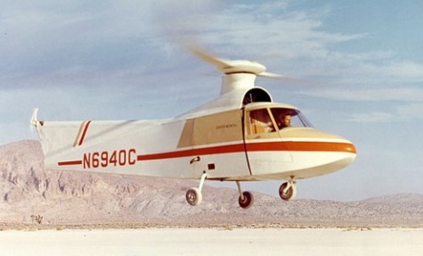
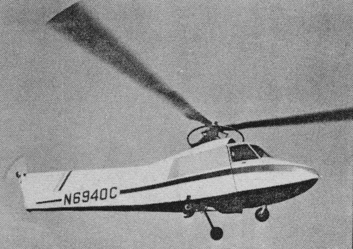
Designated CL-475, this research helicopter had a steel and aluminium tubing covered frame with fabric and a Plexiglass cabin with side-by-side seats. Its 140hp Lycoming VO-360-AIA four-cylinder air-cooled engine initially drove a two-blade wooden rotor, with gyroscopic control being provided by a double metal ‘lollipop’ attached to the blades and connected to the swashplate by springs. In this form the CL-475, which was registered N6940C, was completed in autumn 1959 and was trucked to Rosamond Lake in the Mojave Desert where initial trials could be made without attracting undue attention.
Excessive vibration was encountered during the first flight on 2 November, 1959, and forced Irv Culver’s team to experiment during the next six months with a variety of three- and four-blade wooden rotor designs. The vibration problem, however, was brought within reasonable limits only after the adoption of a three-blade metal rotor and the installation of a new gyroscopic ring attached directly to the swashplate. The CL-475, which in mid-1960 had been moved to the Lockheed facility at Rye Canyon, was then evaluated by FAA, NASA and military pilots and proved to be easy to fly. In fact, a pilot without previous helicopter experience was once able to ferry it alone. Pleased with the results, Lockheed incorporated the rigid-rotor concept in its entry for the US Army light observation helicopter (LOH) competition in 1961. Although the Army did not select this Lockheed design, it had sufficient confidence in the new concept to order jointly with the Navy two Lockheed XH-51 research helicopters.
At the end of its trial programme, the CL-475 was put in storage until 1975, when it was donated by Lockheed to the National Air and Space Museum, Smithsonian Institution. It has now been loaned to the US Army Aviation Museum at Fort Rucker, Alabama.
Lockheed began developing its rigid rotor concept with the CL-475 helicopter design in 1959 and the performance of the CL-475 encouraged Lockheed to continue development. Lockheed submitted the CL-475 to the Army as a candidate to replace the Bell OH-13 Sioux and Hiller OH-23 Raven observation helicopters. Lockheed also tested the commercial market waters without success. However, in February 1962, Lockheed’s Model 186, a new design based on the CL-475 rigid rotor, was selected as the winner for a joint Army-Navy program to evaluate the rigid rotor for high-speed flight capability.
Lockheed CL-475 prototype Registration: N6940C Engine: 1 x 140 hp Lycoming VO-360-AIA Main rotor: three-blade Main rotor diameter: 32 ft Weight: approx 2,000 lb Seats: two side-by-side
In March 1966 Lockheed began development of an advanced armed heli¬copter, designated as the AH 56A Cheyenne. Known as a compound helicopter, being provided with small low set cantilever wings to off load the main rotor in high speed flight, it was designed to have a maximum level speed 244 mph (393 km/h). Army support came to an end in 1969, and economic considerations eventually caused Lock¬heed to end its development programme.
AH-56A Cheyenne Engines: 1 x General Electric T64 GE 16, 3925 shp. Rotor dia: 51 ft 3 in (15.62 m). Length: 60 ft 1 in (18.31 m). Height: 13 ft 8.5 in (4.18 m). Max TO wt: 18,300 lb (8300 kg). Max level speed: 244 mph (393 kph). Range: 1,225 miles. Ceiling: 20,000 ft.