Martin TT

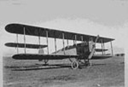
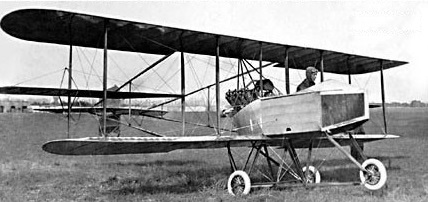
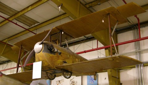
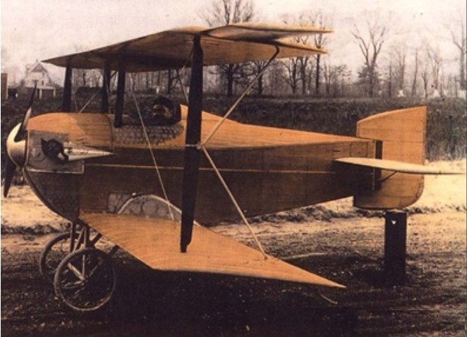
In 1913, Martin won an army contract to produce training aircraft and developed the famed Martin Model TT a tractor biplane with an enclosed fuselage and dual controls, much advanced for its time.
With increasing capital at his disposal, Martin moved to Cleveland. The Glenn L. Martin Company was on its way.

Span: 38’8″
Length: 24′
Seats: 2

Martin Curtiss-type

In 1905, young Martin founded an automobile repair shop. Like many other early aero pioneers, he used the profits from this practical endeavour to support his addiction to the airplane. In 1908, he rented an abandoned Methodist church in Santa Ana, California and built a pusher biplane powered by a Ford engine with which he taught himself to fly. In August 1909 Glenn L. Martin flew the Curtiss-type plane at Santa Ana, California. One year and $3,000 later, this budding high priest of aviation became the first to fly in California. Glenn continued flying, making fund raising exhibition hops.

Span: 40’3″
Length: 38’2″

Martin 1913 Pusher

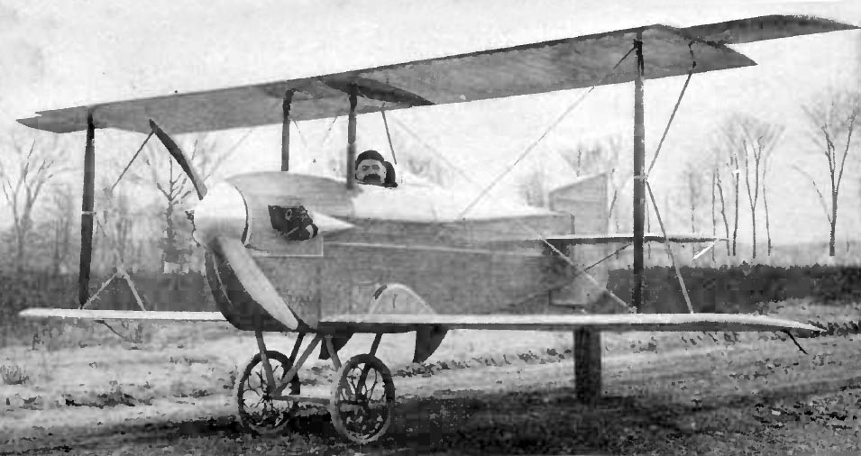
In 1905, young Martin founded an automobile repair shop. Like many other early aero pioneers, he used the profits from this practical endeavour to support his addiction to the airplane. In 1908, he rented an abandoned Methodist church in Santa Ana, California and built a pusher biplane.

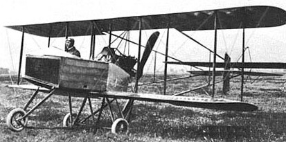
The two place Pusher was powered by a 60-100hp Hall-Scott and featured tricycle gear and twin tail booms. Cost was $5,000.

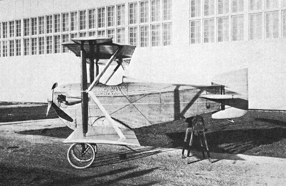
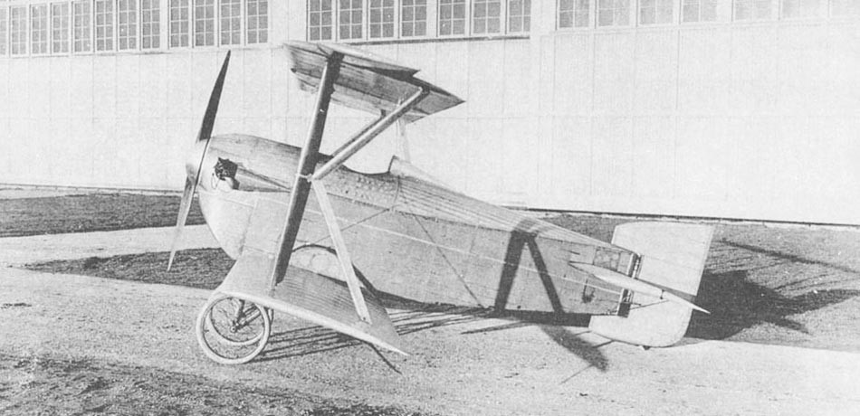
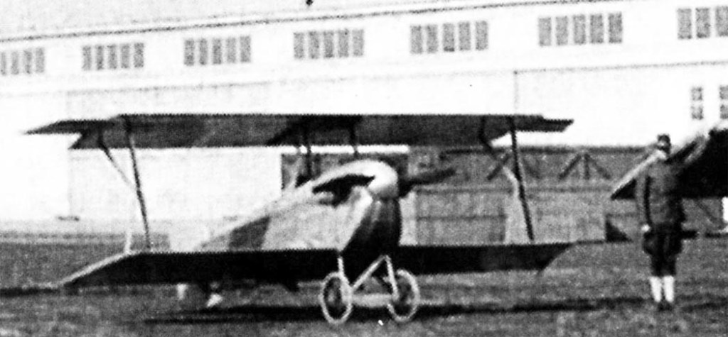
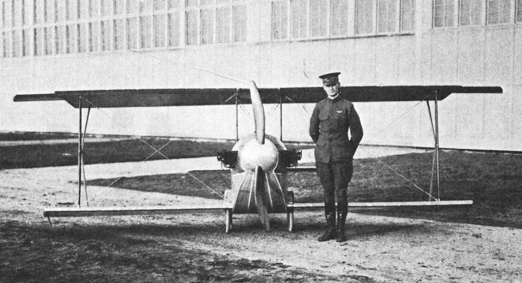
Martin K-3 Kitten / K-4

James V. Martin was a consultant to the U.S. Air service, and an associate to General Billy Mitchell. He held patents on aerospace technologies including the retractable landing gear and once held the World’s speed record of 70 mph in an airplane.

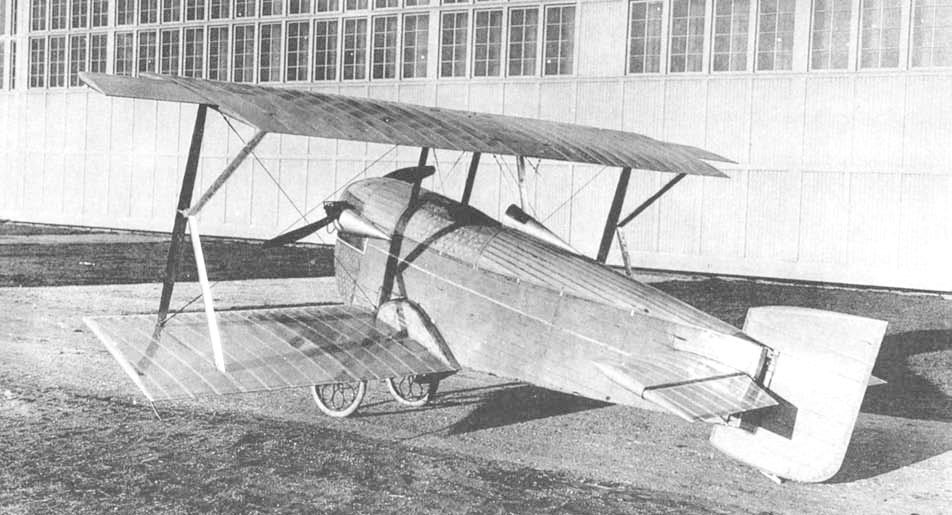
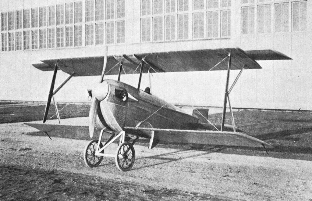
The Martin K-3 was brought out in 1911 as a scout. It was a biplane with a span of 18 ft and overall length of 13 ft 4 in. The Martin landing gear was manually retractable, the wheels folding backward and up between the wing spars into streamlined housings built against the sides of the fuselage.

The wheels used Ackermann flexible spokes for shock absorption. It was powered by an ABC Gnat 40 hp engine and weighed 350 lb. Its high speed was 185 mph. The 9-gallon fuel tank was supposed to provide a flight time of two hours.

When viewed from the side, the wing supports formed a letter “K” shape. The fuselage was all wood with plywood and fabric covering. The aircraft featured air tanks, and electrical power for flightsuit heating. The design included floating ailerons, wing trusses, K-struts and controlled vertical empennage.

Since J.V. Martin did not have a manufacturing facility of his own, building of the K-III and K-IV were contracted out to the Gallaudet Aircraft Corporation, though the J.V. Martin name is the one that applies.

The K.III Kitten was marketed as an “altitude fighter” for the U.S. Army. It is considered the first aircraft in the United States with retractable landing gear.

In December 1918, the aircraft was delivered to McCook Field where it was considered structurally unsound. Martin appealed to Congress in 1920 to no avail. The military refused to fly on it and returned Kitten to the inventor. Only in the spring of next year the plane was tested by a civilian pilot. In 60 test flights at Dayton, Ohio, the high altitude aircraft could only reach 295 ft of altitude.

The prototype K.III Kitten was donated to the National Air and Space Museum in 1924 and survives in the collection.

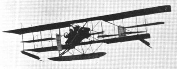
The 1921 J.V. Martin K.IV was a model III with a more powerful 60 hp Lawrance engine and floats. In 1921 3 with float landing gear were built and sold to the U.S. Navy as Navy KF-1.

Martin K-3 Kitten
Engine: ABC Gnat, 45 hp (34 kW)
Wingspan: 20 ft 2 in (6.15 m)
Wing area: 105 sq ft (9.8 m2)
Length: 13 ft 3 in (4.04 m)
Height: 7 ft 4 in (2.24 m)
Empty weight: 350 lb (159 kg)
Normal takeoff weight: 300 kg
Fuel capacity: 9 US gallons (34 litres)
Maximum speed: 117 kn (135 mph, 217 km/h)
Cruising speed: 175km / h
Practical range: 335km
Practical ceiling: 7620 m
Capacity: 1
Undercarriage: retract tail

Martin K.IV / KF-1
Engine: 60 hp Lawrance

Martin 1937 Monoplane

The Martin Monoplane was designed and built in 1937 by C.H.Latimer-Needham and H.Best-Deveraux at Denham, UK, as a low wing, single braced 30.00 ft span monoplane.

It was built using the wings of the Clarke Cheetah G-AAJK and some DH.53 components. It was registered G-AEYY c/n 1 and powered by a Bristol Cherub III engine.

It first flew in October 1937 but crashed on its second flight. It was rebuilt but again was damaged at Meir in 1938. This time it was not rebuilt and it was put into store in Stoke-on-Trent.

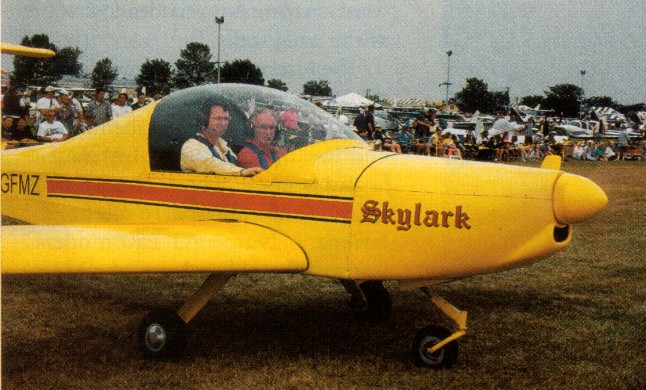
Marsden Skylark

Design of the all metal, T tail, side by side two place Skylark began in January 1999, with the first flight on 10 March 2000. After the first flight, all that was required was a change to the incidence on the horizontal tail.

The Skylark is basically a 6061-T6 aluminium structure aircraft with 0.016 2024-T3 Alclad in the control surfaces. Winglets, engine cowling, tips and main landing gear legs are composite. The wing is tapered with the same wing section across the entire span. A channel type spar, located at 38% chord, is 9 in high and reinforced at the root. It tapers to 7 in at the tip. Each wing panel is fitted with six ribs stamped from 0.025 in 6061 sheet and has three full span skins. Wings are bolted to the fuselage carry-through spar.

Seven foot span, 7.25 in flaperons actuate the flap function mechanically by a handle below the centered throttle quadrant. They reflex (move up) 10 degrees for cruise.

The wing employs an IARV 419 airfoil that was designed by Stephen Marsden. It is a high lift, laminar flow profile specifically designed not to be sensitve to surface roughness due to ice, rain, and snow.

The fuselage is a semi-monocoque structure with three formers aft of the cockpit, which is 43 in wide and has dual controls. A 4.25 cu.ft baggage area is behind the seats. The stabiliser and elevator have a 9 ft span each. A 48 in electrically operated trim tab is installed on the left side of the elevator. The fin is reinforced at the root. Rudder height is 50 in. All of the tail control surfaces are D-cell structures with ribs but no spars. The elevator has six ribs, and the rudder has three.

Main gear legs carry Cleveland wheels and brakes, with 5.00×5 McClreary tires. The nosegear castors, employing a 4130 square steel leg with a spring shock absorber and a 5.00×4 Lamb tire. Main gear tread is 79 in, and wheelbase is 48 in.

Two 14.5 USG welded aluminium fuel tanks are located behind the wing spar, starting at the root and extending 35 in.

Skylark has double tip winglets. As part of the development program, a single winglet was added after the first flight, positioned at the front of the tip. It did assist tip airflow and split the vortices in two parts. Marsden deduced that dual winglets would work better. He added a second winglet, canted out at 45 degrees, that splits the vortices into three parts. This increased effectiveness about 50% over the single winglet.

For takeoff, flaps are set 10 degrees down. On approach, 20 degrees flap are set for landing for better visiblity. The aileron differential is 10 degrees up and 15 degrees down from whatever the flap angle is set.
Downwind approach is at 80 mph, reducing to 70 on base and final, with a touchdown speed of 54 mph.

Engine: Rotax 912, 80 hp
Prop: CSC wood, ground adjustable 68 in
hp range: 85-150
Wingspan: 22 ft
Wing chord: 48 in
Wing area; 92 sq.ft
Empty weight; 655 lb
MAUW: 1200 lb
Fuel capacity: 2 x 14.5 USG
Max level speed; 130 mph
Stall 20 deg flap: 50 mph
Cruise 75%: 120 mph
Fuel burn at 75%: 4 USGph
Econ cruise: 90 mph
Fuel burn at econ cruise: 2.5 USGph
Stress: +6 / -4
Takeoff run; 500 ft
Takeoff speed: 52 mph
Climb rate: 650 fpm at 75-80 mph
Vne: 210 mph
Range at 120 mph: 700 mile
Landing distance: 500 ft