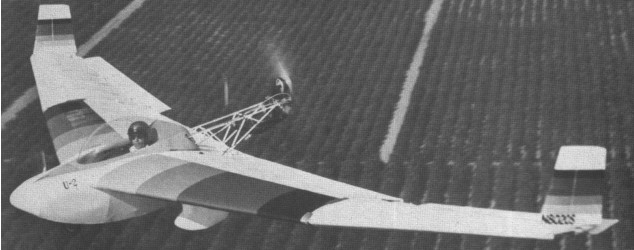
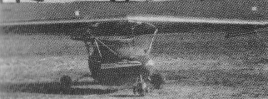
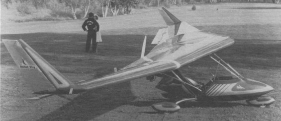
Single seat single engined high wing mono¬plane with conventional three axis control. Wing has swept back leading and trailing edges, and tapering chord; no tall. Pitch/roll control by stabilators; yaw control by tip rudders; control inputs through stick for pitch/roll and pedals for yaw. Cantilever wing: wing profile NACA 23015; double surface. Undercarriage has three wheels in tricycle formation; suspension on all wheels. Push right go right nosewheel steering con¬nected to yaw control. Optional brake on nosewheel.
Mitchell B-10 Article
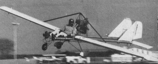
Aluminium tube/wood/steel tube framework, with optional pod. Engine mounted below wing driving pusher propeller.
A hang gliding fanatic, Dr H Long, gave Don Mitchell control of a high performance wing. By 1975 this same wing had become the B 10. The first powered version now carries the designation of B40F (F for foot launch).
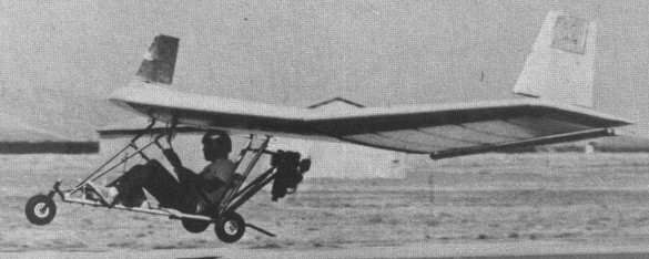
The aircraft is in effect a wing, supporting beneath its lower surface a rigid frame formed by two sets of struts in the shape of an N, at the back of which is mounted a McCulloch Mc101 12hp engine with direct drive to a two blade pusher propeller.
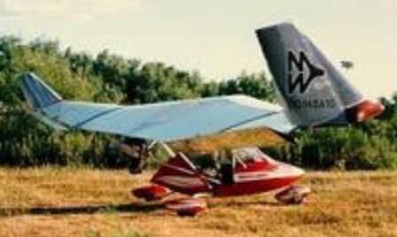
Very quickly Don Mitchell fitted the framework with a tricycle undercarriage with a nosewheel steered by the rudder bar, while a more elaborate version of the B 10 was shown at Oshkosh in August 1981, fitted with a glass fibre fairing and main wheel spats. By 1980, more than 500 sets of plans or kits for the B 10 had been sold. Previously only sold as sets of plans or as a kit, the B 10 Mitchell Wing has been offered factory built, since September 1982.
The structure of each wing has five central ribs in a wooden lattice with six ribs on either side, all of quite conventional construction. The thick plywood spar has D shaped pieces of polyurethene foam resting on it every 4.3 inch (11 cm), which are then covered in 0.04 inch (l mm) thick sheets of plywood to form the leading edge. The control surfaces are made in the same way except for the rudders which have a tubular metallic spar. The covering is of Dacron or aviation quality Ceconite.
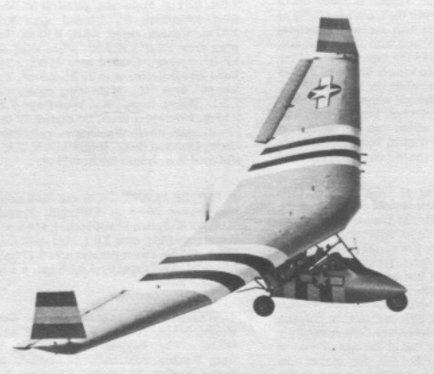
Due to the absence of a tail, roll and pitch control are both provided by stabilators, which span most of each half wing. Controlled from the stick, these stabilators act differentially like ailerons and together as elevators, while the rudders can also act as air brakes. The B 10 Mitchell Wing has dropped the Mc101 engine in favour of the Zenoah G25B. According to Mitchell Aircraft, con¬struction requires 250h of work. The 1983 prices are $6995 ready built, economy kit $1995 (without engine, instru¬ments and undercarriage), homebuilder’s kit $1295 (including raw materials and all hard¬ware but without engine, undercarriage, paint or glue), power pack $1595, tricycle undercarriage $495 and plans $125.
Units and plans delivered by June 1981 1,200 + kits.
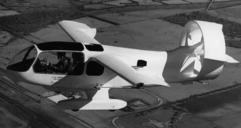
Basically a strengthened B 10, the 1981 prototype of the XF 10 was originally shown by Mitchell Aircraft under the name of SR 10 and is a modified version of the B 10 Mitchell Wing, intended for the military market. This machine is today offered as a kit for an extra $1100 on top of the price of a B 10, compared with which the XF 10 is structurally reinforced and has a faired cockpit as standard. Like the standard B 10, the XF 10 uses the single cylinder Zenoah G2513 1.
Plans for the Mitchell wing B-10 became available from Richard Avalon at US Pacific, 892 Jenevein Ave., San Bruno, CA 94066. The B-10 has held world records by George Worthington. Richard worked with Don just before Don’s death and was not able to carry forward with some planned designs, but Richard is offering Don’s plans.
The Mitchell B-10J is a package available from Jim Gordon’s Micro Aviation. The US$5200 package includes a Garrett JFS100-13 originally used as a starter for the TF-41 engine in the A-7 Corsair. Including throttle package, lubrication and tailpipe assembly, the engine weight is 53 lb, and replaces the Zenoah. First flights were in February 1996, with 80 lb thrust.
Variation:
Bremner Mitchell B10 Wing Special
B-10
Engine: Zenoah G2SB 1, 23 hp at 6500 rpm
Propeller diameter 44 inch, 1.11 m
Toothed belt reduction, ratio 3.0/1
Max static thrust 165 lb, 75 kg
Power per unit area 0.17hp/sq.ft, 1.8hp/sq.m
Fuel capacity 3.0 US gal, 2.5 Imp gal, 11.4 litre
Length overall 6.0ft, 1.83 m
Height overall 4.0ft, 1.21m
Wing span 34.0ft, 10.36m
Chord at root 6.0ft, 1.83 m
Chord at tip 2.0 ft, 0.61 m
Dihedral (On outboard part of wing) 6 deg
Sweepback 12 deg
Total wing area 136 sq.ft, 12.6 sq.m
Wing aspect ratio 8.5/1
Nosewheel diameter overall 10 inch, 25 cm
Main wheels diameter overall 10 inch, 25cm
Empty weight 185 lb, 84kg
Max take off weight 525 lb, 238kg
Payload 340 lb, 154kg
Max wing loading 3.86 lb/sq.ft, 18.8kg/sq.m
Max power loading 22.8 lb/hp, 10.3kg/hp
Load factors; +4.2 ultimate
Max level speed 55 mph, 88 kph
Max cruising speed 45 mph, 72kph
Stalling speed 25mph, 40kph
Max climb rate at sea level 300 ft/min, 1.5 m/s
Min sink rate 225ft/min at 35mph, 1.1m/s at 56 kph
Best glide ratio with power off 16/1
Take off distance 175ft, 53m
Landing distance 175 ft, 53 m
Service ceiling 12,000 ft, 3648 m
Range at average cruising speed 135 mile, 217 km
XF 10
Engine: Zenoah G2SB 1, 23 hp at 6500 rpm
Propeller diameter 44 inch, 1.11 m
Toothed belt reduction, ratio 3.0/1
Max static thrust 165 lb, 75 kg
Power per unit area 0.17hp/sq.ft, 1.8hp/sq.m
Fuel capacity 6.0 US gal, 5.0 Imp gal, 22.7 litre
Length overall 6.0ft, 1.83 m
Height overall 4.0ft, 1.21m
Wing span 34.0ft, 10.36m
Chord at root 6.0ft, 1.83 m
Chord at tip 2.0 ft, 0.61 m
Dihedral (On outboard part of wing) 6 deg
Sweepback 12 deg
Total wing area 136 sq.ft, 12.6 sq.m
Wing aspect ratio 8.5/1
Nosewheel diameter overall 10 inch, 25 cm
Main wheels diameter overall 10 inch, 25cm
Empty weight 200 lb, 91kg
Max take off weight 600 lb, 272kg
Payload 400 lb, 181kg
Max wing loading 4.41 lb/sq.ft, 21.5 kg/sq.m
Max power loading 26.1 lb/hp, 11.8kg/hp
Never exceed speed 50mph, 80kph
Stalling speed 25mph. 40 kph
B-10J
Engine: Garrett JFS100-13, 80 lb thrust
Fuel burn: 10 USGPH
Fuel capacity: 3.5 USG
Endurance: 20-30 min