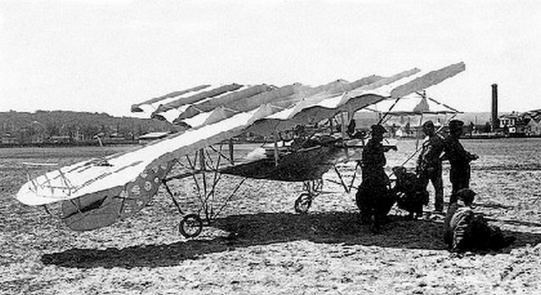
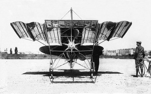
The 1911 Moisant monoplane was designed and built by John Moisant.
The 1911 Moisant monoplane was designed and built by John Moisant.

John Bevins Moisant designed and built two aircraft between August 1909 and 1910, before he became an officially licensed pilot. His first was the Moisant Biplane.
Moisant designed and built the Le Corbeau / Crow in 1910.

John Bevins Moisant designed and built two aircraft between August 1909 and 1910, before he became an officially licensed pilot. His first was the Moisant Biplane. This experimental aircraft became the first all-metal aircraft in the world, being constructed entirely from aluminium and steel. Also known as the “aluminio-plane”, an all-metal sesquiplane built at Issy-les-Moulineaux by American aviator John Benjamin Moisant entirely of steel and aluminium; constructed by workmen hired from the Clément-Bayard airship hangar and completed in February 1910.
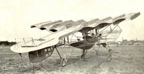
Revolutionary in the construction of its wing – patented by John Moisant (a US citizen) in France as 414,748 – described as aiming to make the machine automatically stable laterally without any form of ailerons or wing warping.
The Moisant biplane’s inaugural flight, and Moisant first flight, ultimately resulted in a crash after ascending only 90 feet.
Engine: Gnôme, 50 hp
Wingspan: 5.5 m
Length: 9 m
Wing area: 22 sq.m
Weight 250 kg
Mohawk Aircraft Corporation formed at Minneapolis in 1927, developing their Spurwing two-seat monoplane with a Warner Scarab engine and similar three-seater Redskin.
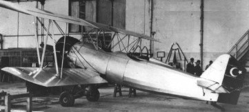
The aircraft designer Selahattin Resit Alan worked after studying in France at the Aircraft-Repair-Center, Eskisehir. Apart from his official activities at the center, he constructed, with the help of the carpenter master Mehmet and a small team, the two-seat training and reconnaissance aircraft MMV-1. The aircraft was ready for flight in October 1932. Except the fact that the aircraft was flown on 29 October 1935 for the ceremonies for the establishment of the Turkish Republic, there is no further indication it was ever flown again. Since the Ministry of Defence did not have any interest in the aircraft, Alan quit his position and began to work with Nuri Demirag in 1935.
For the Maintenance Command Development Centre, Air- Vice Marshal Harjinder Singh of the Indian Air Force designed Kanpur I four-seat light aircraft, prototype built at MCDC in 132 days.
Kanpur II with 250 hp Lycoming engine, first flown October 1961.
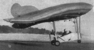
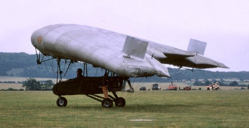
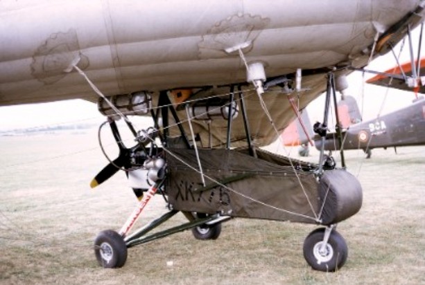
In 1955 ML Aviation at White Waltham designed and produced a portable flying machine called the ML Utility ML.1. Given the serial number XK776, the aircraft featured an inflatable rubberised fabric wing and quick release fittings enabling the aircraft to be rigged and de-rigged fairly quickly.
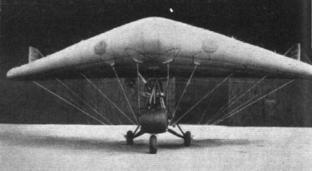
Over the period of a year, the prototype fuselage was redesigned from the box like structure, to a slimmer, longer structure with tandem seating fir a pilot in the front, and passenger. The tricycle undercarriage, with swivelling nosewheel, changed from wheels on a horizontal axle to rear wheels mounted on legs.
The 65 hp McCulloch pylon mounted pusher of the prototype was changed in the Mk.1 to a Walter Mikron in a cowling faired into the rear of the fuselage. Fuel was a mix of methanol, benzole, and petrol. Cruising speed increased from 45 mph to 58 mph.
The inflatable rubberised-fabric wing, of delta planform, was cleaned up. The basic structural method was retained with the upper and lower surfaces being connected by a number of porous fabric diaphtrams running spanwise and maintaining a symmetrical aerofoil profile developed from NACA 0024. After initial inflation on the ground, the wing is maintained at its correct internal pressure, under 1 lb/sq.in, by an electric pump and relief valve. The prototype had a windmill operated pump.
Control was by inflated elevons over almost the full span of the trailing edge, operated by cable from an inverted control column mounted on the fuselage superstructure. Vertical stabilising surfaces fitted near the wingtips replaced the central fin of the prototype.
The whole wing can be deflated and packed in a bag. The wing is attached to the superstructure by a series of toggles, and flying wires lead from patches on the wing undersurface to points on the fuselage and undercarriage members.
Despite evaluation by the British Army Air Corps at Middle Wallop further production was not taken up. The flight characteristics were unusually slow and the machine was then stored until saved by the Army Air Corps museum.
This was an experimental 2-seat observation aircraft built in 1957 for the Army. Fuselage consisted of a canvas bathtub type fuselage reminiscent of some later microlight aircraft.
XK776 was the first of three inflatable wing aircraft flight tested between 1954 & 1960. It went to Cardington on 27/11/69, and is now preserved at the Museum of Army Flying at Middle Wallop.
Utility Mk.1 Prototype
Engine: 65 hp McCulloch
Utility Mk.1
Engine: Walter Mikron III
Span: 35 ft 0 in
Overall length: 23 ft 3 in
Overall height: 10 ft 6 in
Wing area: 400 sq.ft
Dry weight: 450 lb
Fuel: 85 lb
Pilot weight; 180 lb
Passenger weight: 180 lb
Baggage weight: 40 lb
Total weight: 935 lb
Max speed: 68 mph
Cruise: 58 mph
Stall: 30 mph
Rate of climb: 740 fpm
Takeoff distance: 210 ft
Endurance: 2 hr 30 min
Ceiling: 5000 ft
Root chord: 17 ft 6 in
Tip chord: 5 ft 9 in
Wheelbase: 7 ft 1 in
Track: 5 ft 4 in
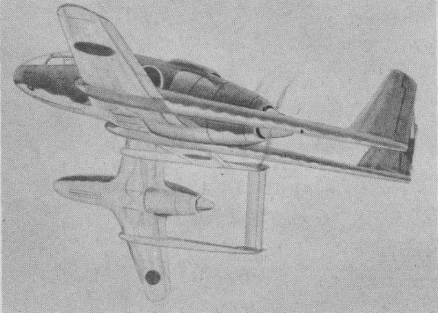
The Mitsubishi J4M1 was discovered in a captured document, receiving the allied code name ‘Luke’. Although featuring in a December 1944 recognition manual, the prototype was never completed.
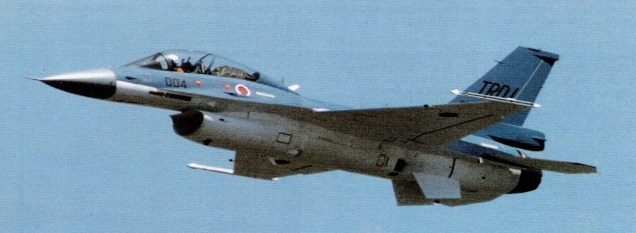
The Japanese-developed F-2 fighter support aircraft, intended to replace F-1 and based on F-16 but incorporating new technologies was developed jointly with Lockheed. The fighter uses an all-composite wing. The Japanese Defense Agency approved a 55 aircraft purchase for 2000-1.
Early in October 1987, Japan announced that the FS-X would be a derivative of an existing US aircraft, the choice of the basic airframe being either the F-16 of the F-15. The F-16 derivative was selected by the Japanese Self-Defense Agency with formal endorsement of the Japanese National Security Council in October 1987.
The first prototype flew on 7 October 1995, and the first squadron to be equipped with the F-2 was formed in 2000.
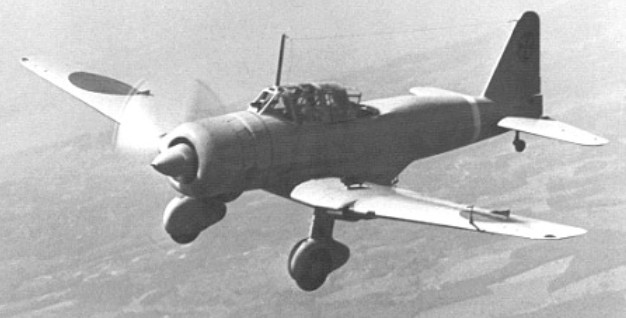
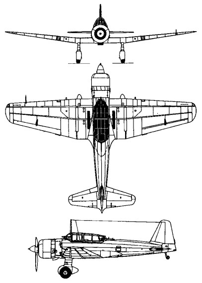
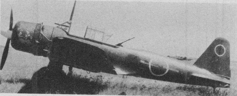
To meet an Imperial Japanese Army specification of December 1937 for a two seat ground-attack aircraft, which it was suggested could be a development of the Ki-30 light bomber, Mitsubishi produced two prototypes under the designation Mitsubishi Ki-51.
The Ki 51 was a cantilever low wing monoplane, with a ‘trousered’ and spatted non retractable main landing gear and a fixed tail wheel. The powerplant for both prototype and production aircraft was a single 940 hp Mitsubishi Ha 26 II 14 cylinder air cooled radial engine, driving a three blade variable pitch metal propeller. The greenhouse canopy was shorter than that on the Ki 30, bringing the two man crew closer together, and a degree of armour protection was provided for the occupants and the engine. The Ki 51 differed from the Ki 30 in having no internal bomb bay, the normal 200-kg (440 lb) weapon load being carried externally. Overall construction was of metal except for the control surfaces, which were fabric covered.
Two prototypes, designated Ki 51, were completed in June and August 1939, followed immediately by a pre series batch of 11 more, all completed by the end of that year. They differed from the prototypes by incorporating a number of modifications, including the introduction of fixed leading-edge slots to improve slow-speed handling and armour plate beneath the engine and crew positions.
After a virtually problem free flight test programme, and only a few minor modifica¬tions, the Ki 51 entered production in January 1940 as the Army Type 99 Assault Aircraft. From then until March 1944 Mit¬subishi’s Nagoya factory manufactured a total of 1459. Four months later a second production line was established by Tachikawa, which had completed a further 913 by July 1945. Standard armament at first consisted of three 7.7 mm (0.303 in) Type 89 machine guns, one in each wing and one in a movable mounting in the rear cockpit. On later aircraft, the wing mounted pair were exchanged for Type 1 guns of 12.7 mm (0.5¬in) calibre, and the aircraft’s range was increased by installing a 68 litre (15 Imp gal) fuel tank in each wing leading edge. The Ki¬-51 served with at least eight Sentais (groups) and a dozen or more independent squadrons of the Japanese army air force, from 1940 until the end of the Second World War. It established a reputation for being reliable and capable of surviving considerable battle dam¬age, which made it popular with its crews. It was given the Pacific codename Sonia by the Allies. Adapted, inevitably, for the kamikaze role towards the end of the war, it was flown as a single seater, carrying a 250 kg (550 lb) bomb beneath the fuselage.
In addition to the standard production aircraft, there were attempts to develop dedicated reconnaissance versions, initially by the conversion of one Ki-51 service trials aircraft which had the rear cockpit redesigned to accommodate reconnaissance cameras. Test and evaluation of this aircraft, redesignated Ki-51a, brought a realization that the standard Ki-51 could be modified to have provisions for the installation of reconnaissance cameras, and this change was made on the production line.
Three prototypes were completed at Tachikawa of the Ki 71 (codenamed Edna), an improved, retractable gear version with a 1500 hp / 1119kW Mitsubishi Ha-112-11 engine and two 20mm wing cannon, but no production orders for this type were placed.
Allocated the Allied codename ‘Sonia’, the Ki-51 was used initially in operations against China, and was deployed against the Allies until the end of the Pacific war. In more intensely contested areas the fairly slow Ki-51s were easy prey for Allied fighters, but in secondary theatres, where an ability to operate from rough and short fields was valuable, these aircraft gave essential close support in countless operations. In the closing stages of the war they were used in kamikaze attacks.
Ki-51
Engine: 940 hp / 705kW Mitsubishi Ha 26 II radial
Prop: three blade variable pitch metal
Wingspan: 12.1 m / 39 ft 8 in
Length: 9.21 m / 30 ft 3 in
Height: 2.73 m / 8 ft 11 in
Wing area: 24.02 sq.m / 258.55 sq ft
Max take-off weight: 2798-2920 kg / 6169 – 6438 lb
Empty weight: 1873 kg / 4129 lb
Max. speed: 424 km/h / 263 mph
Ceiling: 8270 m / 27150 ft
Range: 1060 km / 659 miles
Crew: 2
Armament: 3 x 7.7mm machine-guns, 200-300kg of bombs
Tachikawa Ki-71
Engine: 1500 hp / 1119kW Mitsubishi Ha-112-11
Undercarriage: retractable
Armament: two 20mm wing cannon