In 1945 the Rotor-Craft Corporation began developmental work on a helicopter with tandem rotor configuration, designed by its President, Gilbert W. Magill, and embodying various novel features, especially the use of a rigid rotor system. The only designer in the United States to have preceded Magill in this line was Landgraf, who employed side-by-side rotor blades fixed rigidly to the hubs.
In 1953 Rotor-Craft acquired the patents of the Landgraf Helicopter Company, including those related to ‘rigid rotors’. At the time Magill stated: ‘Rigid rotor helicopters will be less costly to produce, and the safety of rigid blades that cannot droop and endanger passengers or others approaching the machine is expected to be attractive to both armed services and commercial helicopter operators.’
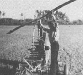
The absence of reliable technical data about its own particular version of the rigid rotor concept decided Rotor-Craft to design a test stand which would enable a quarter-scale rotor assembly to be thoroughly tested during the developmental stage.
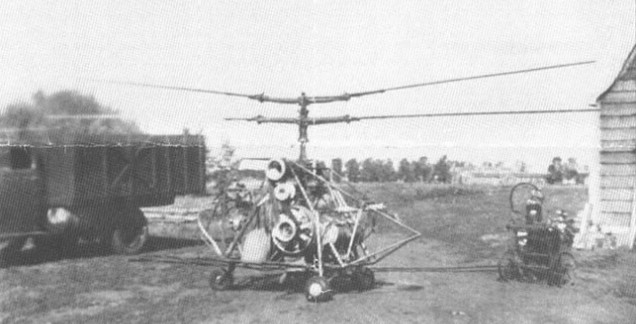
This helicopter had two three-bladed rotors set in tandem and overlapping though separated by a distance of 3.76m; the level of the rear rotor was above that of the forward rotor.
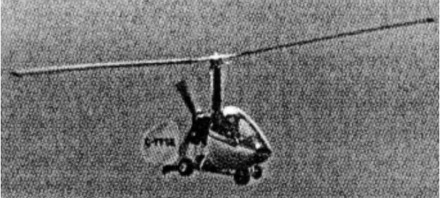
The Rotor-Craft XR-11, designed by Mr. Gilbert Magill, is so far the only tandem rotor helicopter to have flown with rigid blades, and it is claimed that inherent stability has been built into the design without resorting to the use of auxiliary aerofoils or gyroscopic weights. Soon the designation of the helicopter was changed to XH-11. It was under development for the U.S.A.F. for three years, then tested at the Cal-Aero Technical Institute at Glendale, California.
A feature of the XR-11 is the rigid mounting of the rotor blades, without hinges or flapping joints, the rotor discs constantly remaining perpendicular to the shafts and following broadly the principle of the controllable-pitch airscrew. The blades were connected in such a way that their span axis was at the rear of the driving shaft. Pitch control rods are enclosed in hollow drive shafts, resulting in a very clean assembly. The blade roots embody levers, which enter the hollow drive shafts via slots, connecting with their respective pitch control rods; the two three-bladed oppositely rotating rotors are mounted in tandem and overlap, the forward rotar turning anti-clockwise and the aft rotor turning clockwise. It is of interest to note that the c of g location is some 40% to the rear of the forward rotor shaft, which is therefore carrying some 50% greater disc loading than the rear shaft.
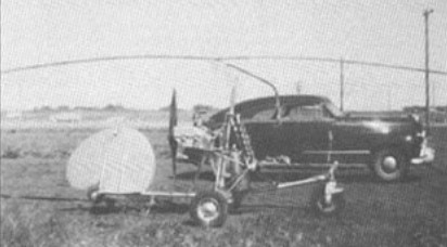
Swashplates for cyclic and collective pitch changes are positioned at the bases of the rotor drive shafts, eliminating a number of components normally used for transferring control movements. For forward or backward flight the swash-plate was tilted fore and aft by a push-pull rod, while collective pitch change was obtained by raising or lowering another push-pull rod. Mr. Magill claims that the control system is extremely sensitive and the lag in control response is almost imperceptible. A number of standard automotive parts are incorporated in the structure, reducing initial costs and maintenance time. The clutch and gears in the rotor assembly are reworked Ford units, a Studebaker free-wheeling unit is employed and all the universal joints are standard car accessories.
Welded steel-tube construction is used for the fuselage and the rotor blades are of laminated birch construction.
The project was ultimately cancelled.
Randall Franklin, 13.01.2007 In 1948 I was 18 going to college and as a hobby designing a helicopter. By chance I met Gilbert Magill, and he was kind enough to advise me on my plans. He gave me a job at Rotot Craft working in the shop while developing the Dragon Fly. I did minor jobs of fileing tubing for welds etc. I witnessed it’s disastrous test flight. It got on the ground cushion and fell about 3 feet. The tube framing was hinged and an adjustable link was above the pilot head. That adjustment sheared and the fuselage collapsed in half. The rotors seperated in all directions and one missed my head by a foot or two. The pilot was uninjured but looked stunned. This happened at the Grand Central Air Terminal in Glendale Ca. The swash plates were at the bottom of the masts. Very much like the Enstrom Helicopter of today. Magill was a true genious, and years ahead of his time. One of the big investors in this helicopter was Lucille Ball. This early helicopter experience qualified me to be in the US Army’s first helicopter class at Ft. Sill OK. I flew in the Korean War, and later many years with World Wide Helicopters all over the world. I owe many thanks to Gilbert Magill, for a long and exciting career in helicopters. I regret that I have lost contact with him.
In 1945 William Thomas, President of the Roteron Corporation, began work on a midget helicopter of an original design. By placing its 5-cylinder engine between the two co-axial rotors, he had more space available in the fuselage, and considerable saving in construction also resulted because power was directly transmitted to the rotors.
The rotors each had two sets of blades, a longer set below a shorter set which, produced an anti-torque effect. Both sets of blades were made of solid laminated maple wood. The pitch and speed of either rotor could be controlled and in case of engine failure they could turn by auto-rotation.
The fuselage consisted of a steel tubing frame covered with an aluminium skin and plastic covering. The rudder, supported at the end of two tubes, could pivot from the vertical to the semi-horizontal position. The tricycle undercarriage had three fully swivelling wheels.
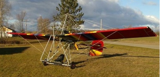
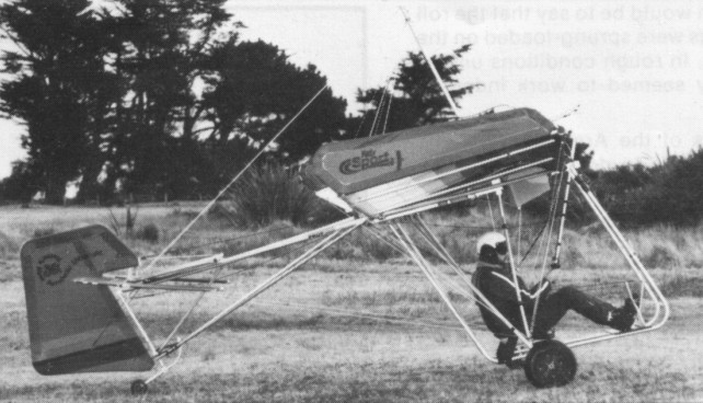
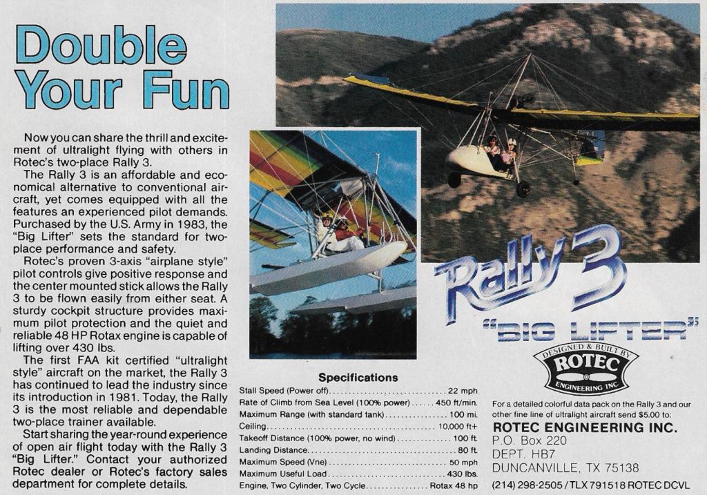
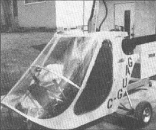
The Rotec Rally line has grown out of the solid aeronautical engineering and helicopter-rated experience of William Adaska. The pilot sits inside a roll cage in the manner of a stock car. The control column is pivoted from above so that in the event of a head on collision with the ground it pushes out of the way, instead of into the pilot’s stomach. The 48 hp engine is mount¬ed above and aft of the wing for pilot safety.
The Rotec Rally line-up are all equipped with standard rudder pedals and stick; providing three axis aerodynamics like any normal aeroplane. However, possibly be¬cause of the designer’s helicopter back-ground, the throttle is a twist-grip mounted on the control stick. All tubing is aircraft grade 6061-T6 anodised aluminium and hardware is aircraft quality AN material. Cables are aircraft grade stainless steel 7 x 7 vinyl coated.
Accompanying each aircraft is a 145 page assembly manual and a 95 page pilot’s manual that covers all aspects of microlight flying. Different sized wheels are available. The standard size is the 20” which would give the Rally Sport an even higher ground clearance than the 4” wide 16” ‘Tundra” tyres; fitted to decrease side loads during cross wind landings and take the bumps out of rough ground and river bed landings. The Rally 3 was even higher; 13.5 inches.
The Rally models could be derigged for transport on a trailer and rerigged in about 45 minutes. All slip pins were safety locked with split rings. The trailing tail wheel is bungee. Spoilerons are held down by a bungee cord which makes for a positive feel in flight. The 48 hp engine is fan cooled making for efficient cooling and the “see through” 5 gallon fuel tank provides about 2 and a half hours endurance at normal revs.
The wing is a single surface of 3.8 oz dacron, available in a variety of colours already sewn at the factory.
Special custom sails are available. End plates add to the lifting capacity. Maximum “G” for the Sport is given as plus six and minus three.
Elevators are described as being “Butter¬fly” to provide strong pitch control for rapid aerobatic manoeuvres. The elevator sur¬faces surrounding the sides and trailing edge of the stabiliser are aerodynamically balanced to allow minimal force on the con¬trol stick at all speeds. Each Rally can have its controls set to suit the pilot. There is an optional adjustable seat which allows the pilot or the passenger to slide into the most comfort¬able position. The joystick is adjusted by the simple method of tightening or loosening the control cables.
The Rally 1 is a high-wing monoplane with con¬ventional tail unit much like the Rally 2B. Rather than stick and pedal controls, the weight shift is used for roll and pitch control, with the pilot in a sling seat. POWERPLANT: Zenoah in pusher position above the wing, and a 2.4:1 reduction unit. Otherwise similar to Rally 2B. LANDING GEAR: Similar to Rally 2B. Top mounted joy stick, rudder pedals, castering tailwheel. First built; 1976.
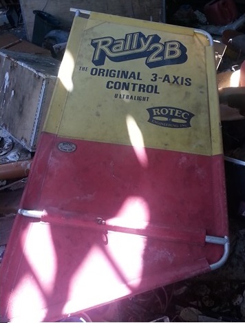
The Rally 2B is a high-wing monoplane with con¬ventional tail assembly consisting of horizontal and vertical stabilizers. The elevators are separate and the rudder is all ¬flying. Roll is controlled by ailerons and can be operated separately from the foot-controlled rudder by means of an inverted control stick. Construction makes use of aluminum tubing and steel aircraft cable. The wings and tail surfaces are covered with Dacron with clear windows at both wing roots. The engine is mounted in a pusher position above the wing. A 2.4:1 reduction unit turns a two-blade wooden propeller made by Rotec. Fuel is carried in an ABS plastic tank hung under the wing root area. LANDING GEAR: Conventional taildragger gear are shock mounted with bungee wrap. The tailwheel is castering, and the main wheels measure 20 inches in diameter. There are no brakes. The Rally 2B was first built in 1976 and by June 1981 500 had been delivered.
The United States Marine Corp have bought the Rally 2B, as have the Department of the Interior Geological Sur¬vey Team.
The 1981 standard version of the Rally 2B used ailerons attached to the trailing edge of the outer sections of the wing. This method was dropped in favour of spoilerons carried on the upper surface of the wing and mounted at 1/3 chord back from the leading edge. The Rally 2B is sold as a kit for $4800 in March 1983, options including an instrument panel, transport covers for $350, floats $950, skis $280, windshield $72 and transparent panels for the first third of the span of each wing $150. The Rally 2B is sold ready built for an extra $680.
The Rally 2B Twin is similar to the Rally 2B. POWER-PLANT: Zenoah-Twin mounted in a pusher position above the wing. A 2.4:1 reduction unit turns a two-blade wooden pro¬peller made by Rotec. Otherwise similar to the Rally 2B. LANDING GEAR: Similar to the Rally 2B. The aircraft is also available in 2B+ form, with a different wing design incorporating extra ribs and more camber and billow, a combination which Rotec says gives better pitch stability.
The 2B is a three axis design and initially used the same engine as the Rally 2, but various other units were substituted, including a Solo with 2.7/1 reduction drive, developing 20hp at 5200rpm, (the 2B1 version) and a twin cylinder 292cc 30hp Chaparral unit (the 2B2 version, sold in the US with floats, under the name Rally Marine). Some aircraft were also made with the 28 hp Kohler engine.
In 1983, customers had the choice of 40 hp Kawasaki, 35 hp Cuyuna or 32 hp Rotax engines.
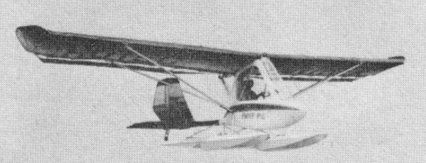
The Rally Marine is similar to Rally 2B. POWERPLANT: Zenoah-Twin mounted in pusher position above the wing. Similar to the Rally 2B Twin. LANDING GEAR: Standard gear are replaced by two 9-foot foam pontoons.
The Rally Sport has roll control by three quarter span spoilerons; suspension on all wheels. Announced on 1 March 1983, this single seater from Bill Adaska is, according to the company, ‘an optimised airplane rather than an innovative airplane’. In fact, apart from an obvious family resemblance, the Rally Sport does not have a great deal in common with the earlier Rallys. Certainly its performance characteristics are very different, particularly its maximum roll rate, which is quoted as 150 deg/s.
The Rally Sport is offered, after a year of test flights by its manufacturer, as an acrobatic ultralight. The wing design is considerably changed from the 2B, with smaller span and area and saumons at the tips, while a dramatic roll rate comes from three quarter span spoilers, compared with one third span for the 2B. The tail uses aerodynamically balanced elevators which surround the edges of the horizontal stabiliser giving the effect of servo tabs. Power comes from the Rotax 503, used in the same form as on the Rotec two seater, the Rally 3B. The machine was sold as a kit for $5600 or ready to fly for an extra $680 in 1982. There is an option of transport covers for $325. Shorter wing and airframe beefing gives Rally Sport a load factor of + 6, -3 G’s for aerobatics. With a top mounted joy stick, rudder pedals, castering tailwheel, the Rally Sport was first built in 1976.
Developed for the Rotec Rally is a spray system carrying 24 gallons and with spray booms attached to the wings to provide a 45 foot spray pattern. With an application of three gallons per minute while flying at 30 mph, the Rally should cover 2.7 acres a minute.
The Rally 3 is a side by side two seater version of the Rally 2B, with conventional 3 axis controls. Roll control by spoilerons. Nylon rope suspension on all wheels. This two seat version of the Rally is sometimes known as the Big Lifter and received FAA experimental certification on 18 November 1981, after more than 12 months’ trials by Rotec, first sales being the following January.
Rally 3
It differs from the single seat 2B mainly in having an enlarged framework, with a third cranked tube running longitudinally, and an enlarged span, though the chord remains the same. As on the Rally Sport, the horizontal stabiliser uses aerodynamically balanced ‘ser¬vo tabs’. Originally powered by the Cuyuna 430R, the aircraft now comes with a Rotax 503 for which 48 hp is quoted.
At the end of 1982 Rotec announced what it calls the ‘jump option’ under which the aircraft was converted to carry a parachutist. This is done by removing the second set of pedals and adding a sliding seat and trapeze bar, while for jumpers who prefer to start their descent from a standing position, a platform can be fitted.
The two main wheels of the Rally 3 can be replaced by mahogany skis with a glass fibre surface as a $320 option, while saumons as on the Rally Sport can also be added as an extra. Further options include transport covers for $450, floats for $1250 and a windshield for $116 (in 1982).
Although offered in January 1983 for $5000, the normal price of a Rally 3 in standard form is $6000 as a kit; it is not available ready built in the US because it is classified as an experimental aircraft under US legislation. The United States Army has purchased 300 of the Rally 3 with a 500 lb payload which would typically consist of two persons and some weapons and features a minimum cruise speed of 45 mph with a range of 200 nm on 16 gallons of fuel. The Army required the aircraft to have a 10,000 foot ceiling, rough field landing capability and to be capable of assembly out in the field by two persons in 30 minutes.
July 1984
Elsewhere it can be bought ready built for an extra $960, while in France, where it is imported to special order only and known as the Rally 4B2S, it is fitted with a Hirth 276R engine developing 36hp at 6250 rpm.
Feb 2014 wraupert@namibnet.com Can someone please help me with a pdf-copy of an assembly manual for the Rotec Rally 2b, mine got lost and i would like to put my Rally together and fly it again. Thanx alot in advance! regards, Werner
Rally 1 Engine displacement 240cc Rated HP, 20 hp Static thrust, 170 lbs Wingspan, 31 ft Wing area, 155 sq.ft Aspect ratio, 6.4:1 Overall length, 14.5 ft Empty weight, 125 lb Usable payload (include fuel), 232 lb Wing loading, 2.3 lbs/sq.ft L/D power-off glide ratio, 7.5:1 Cruise speed (85% power), 34 mph Stall speed, 16 mph Approach speed, 25 mph Flair speed, 20 mph Liftoff speed, 18-20 mph Takeoff roll distance, 90 ft Rate of climb, 400 fpm Fuel capacity, 2 USgal Range at cruise, 60 mi Seats: 1
Rally 2B Engine Zenoah, displacement, 240cc, 20 hp Static thrust, 170 lb Wingspan, 31 ft Wing area, 155 sq.ft Aspect ratio, 6.4:1 Overall length, 15.7 ft Empty weight, 135 lb Usable payload (include fuel), 232 lbs Wing loading, 2.4 lbs/sq.ft L/D power-off glide ratio, 7:1 Cruise speed (85% power), 32 mph Stall speed, 16 mph Ap¬proach speed, 25 mph Flair speed, 20 mph Liftoff speed, 18-20 mph Takeoff roll distance, 90 ft Rate of climb, 350 fpm Fuel capacity, 2 Usgal Range at cruise, 60 mi
Engine: Cuyuna 430R, 35 hp at 5500 rpm Propeller diameter and pitch 54 x 32 inch, 1.37 x 0.81 m Toothed ¬belt reduction Power per unit area 0.22hp/sq.ft, 2.4hp/sq.m Fuel capacity 3.5 US gal, 2.9 Imp gal, 13.2 litre Length overall 16.8 ft, 5. 13 m Height overall 10.3ft, 3.15m Wing span 31.0ft, 9.44m Constant chord 5.0 ft, 1.52 m Total wing area 155sq.ft, 14.4sq.m Rudder area 12.3sq.ft. 1.14 sq.m Total elevator area 7.6 sq.ft, 0.70 sq.m Wing aspect ratio 6.2/1 Main wheels diameter overall 20 inch, 51 cm Empty weight 218 lb, 99kg Max take off weight 466 lb, 211kg Payload 248 lb, 112kg Max wing loading 3.00 lb/sq.ft, 14.7 kg/sq.m Max power loading 13.3 lb/hp, 6.0kg/hp Load factors +3.0, 1.5 design; +3.8, 2.0 ultimate Max level speed 50 mph, 80 kph Never exceed speed 55 mph, 88 kph Max cruising speed 40 mph, 64 kph Economic cruising speed 35 mph, 56 kph Stalling speed 19 mph, 30 kph Max climb rate at sea level 680 fpm, 3.5 m/s Min sink rate 275 fpm, 1.4 m/s Best glide ratio with power off 7/1 Take off distance 75 ft, 23 m Land¬ing distance 50 ft, 15 m Service ceiling 10,000ft, 3050 m Range at average cruising speed 78 mile, 125 km
Engine: Rotax 377, 38 hp at 6600 rpm Propeller diameter and pitch 54 x 34 inch, 1.37 x 0.86 m Toothed ¬belt reduction, ratio 2.2/1 Max static thrust 280 lb, 127 kg Power per unit area 0.25hp/sq.ft, 2.6hp/sq.m Fuel capacity 5.0 US gal, 4.2 Imp gal, 18.9 litre Length overall 16.8 ft, 5. 13 m Height overall 10.3ft, 3.15m Wing span 31.0ft, 9.44m Constant chord 5.0 ft, 1.52 m Total wing area 155sq.ft, 14.4sq.m Rudder area 12.3sq.ft. 1.14 sq.m Total elevator area 7.6 sq.ft, 0.70 sq.m Wing aspect ratio 6.2/1 Main wheels diameter overall 20 inch, 51 cm Empty weight 218 lb, 99kg Max take off weight 466 lb, 211kg Payload 248 lb, 112kg Max wing loading 3.00 lb/sq.ft, 14.7 kg/sq.m Max power loading 12.3 lb/hp, 5.6kg/hp Load factors +3.0, 1.5 design; +3.8, 2.0 ultimate Max level speed 50 mph, 80 kph Never exceed speed 55 mph, 88 kph Max cruising speed 45 mph, 72 kph Stalling speed 19 mph, 30 kph Max climb rate at sea level 700 fpm, 3.6 m/s Best glide ratio with power off 7/1
Rally 2B Twin Engine Zenoah twin displacement, 300cc, 30 hp Static thrust, 255 lb Wingspan, 31 ft Wing area, 155 sq.ft Aspect ratio, 6.4:1 Overall length, 15.7 ft Empty weight, 170 lb Usable payload (include fuel), 270 lb Wing loading; 2.8 Ibs/sq.ft L/D power-off glide ratio, 6.5:1 Cruise speed (85% power), 44 mph Stall speed, 18 mph Approach speed, 25 mph Flair speed, 20 mph Liftoff speed, 18-20 mph Takeoff roll distance, 70 ft Rate of climb, 800 fpm Fuel capacity, 4 USG Range at cruise, 110 mi
Rally 3 Engine: Rotax 503, 48 hp at 6250 rpm Propeller diameter and pitch 60 x 28 inch, 1.52 x 0.71 m Toothed belt reduction, ratio 2.3/1 Max static thrust 338 lb, 153 kg Power per unit area 0.25 hp/sq.ft, 2.7 hp/sq.m Length overall 17.3 ft, 5.28 m Height overall 10.7ft, 3.25m Wing span 38.0ft, 11.58m Constant chord 5.0 ft, 1.52 m Total wing area 190sq.ft, 12.7 sq.m Wing aspect ratio 7.6/1 Main wheels diameter overall 16 inch, 41 cm Empty weight 265 lb, 120kg Max take off weight 695 lb, 315kg Payload 430 lb, 195kg Max wing loading 3.66 lb/sq.ft, 17.8 kg/sq.m Max power loading 14.5 lb/hp, 6.6 kg/hp Max level speed 45 mph, 72 kph Max cruising speed 40 mph, 64kph Stalling speed 20mph, 32kph Max climb rate at sea level 450 ft/min, 2.3 m/s Best glide ratio with power off 7/1 Take off distance 100ft, 30m Landing dis¬tance 80ft, 25m Service ceiling 10,000ft, 3050m Range at average cruising speed 100 mile, 161 km
Rally 3 Big Lifter Engine – 2 cyl two stroke: 48 hp Wing Span: 38 ft Wing Area: 190 sq ft Length: 17′ 4″ Height: 10′ 8″ Cruise Speed: 40 mph Max Speed (Vne): 50 mph Max Range Standard: 100 miles Stall Speed (100% Power): 20 mph Stall Speed – Power Off: 22 mph Take-off Distance: 100 ft Landing Distance: 80 feet Rate of Climb s/l: 450 fpm Ceiling: 10,000 ft Glide Ratio: 7.1 Wing Loading: 3.2 lb/sq ft Empty Wt: 285lb Max Payload: 430lb
Rally Marine Engine displacement, 300cc, 30 hp Static thrust, 255 lb Wingspan, 31 ft Wing area, 155 sq.ft Aspect ratio, 6.4:1 Overall length, 16 ft Empty weight, 220 lb Usable payload (include fuel), 250 lb Wing loading, 3 lbs/sq.ft L/D power-off glide ratio, 6.5:1 Cruise speed (85% power), 40 mph Stall speed, 18 mph Approach speed, 25 mph Flair speed, 20 mph Liftoff speed, 18-20 mph Takeoff roll distance, 90 ft Rate of climb, 650 fpm Fuel capacity, 4 USG Range at cruise, 100 mi
Rally Sport Engine: Rotax 503, 48 hp at 6250 rpm Propeller diameter and pitch 60 x 28 inch, 1.52 x 0.71 m Toothed belt reduction, ratio 2.3/1 Max static thrust 338 lb, 153 kg Power per unit area 0.36 hp/sq.ft, 3.8 hp/sq.m Fuel capacity 3.5 US gal, 2.9 Imp gal, 13.2 litre Length overall 16.6 ft, 5.05 m Height overall 10.4ft, 3.15m Wing span 27.0ft, 8.23m Constant chord 5.0 ft, 1.52 m Total wing area 135 sq.ft, 12.5 sq.m Wing aspect ratio 5.4/1 Empty weight 248 lb, 112kg Max take off weight 468 lb, 212kg Payload 220 lb, 100kg Max wing loading 3.461b/sq.ft, 16.9kg/m Max power loading 9.8 lb/hp, 4.4kg/hp Load factors; +6.0, 3.0 ultimate Max level speed 60 mph, 97 kph Never exceed speed 60 mph, 97kph Max cruising speed 50mph, 80kph Stalling speed 20 mph, 32 kph Max climb rate at sea level 1000 ft/min, 5.1 m/s Best glide ratio with power off 6.8/1 Take off distance 70ft, 21m Landing dis¬tance 75ft, 23m Service ceiling 10,000ft, 3050m Range at average cruising speed 83 mile, 134km Roll rate: 150 deg/sec
Rally Super Sport Cruise Speed: 50 mph Max Speed (Vne): 60 mph Max Range Standard: 83 miles Stall Speed (100% Power): 20 mph Stall Speed – Power Off: 23 mph Take-off Distance: 70 ft Landing Distance: 75 ft Rate Of Climb s/l: 1000 fpm Ceiling: 10,000 ft Max G-Load: + 6, -3g Max Roll Rate: 150 deg/sec Glide Ratio: 6.81 Wing Loading: 3.3 lb/sq ft Power Loading: 9.31 lb/hp Wing Span: 27 ft Wing Area: 135 sq ft Length: 16′ 7” Height: 10′ 4″ Engine – 2 cyl two stroke, 48 hp Empty Wt: 248lb Max Payload: 220lb
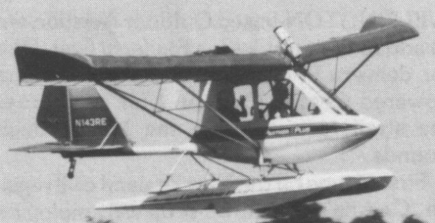
A fully enclosed, strut braced double surface wing, spatted undercarriage ultralight. Centre mounted joy stick, rudder pedals, tailwheel steerable through rudder pedals.
Rotec Panther 2 Plus includes a float option, brakes, cabin heat, executive interior (includes carpet), ballistic parachute (mounted on wing above cabin) and Loran C navigational equipment.
Panther Engine: Rotax 277 (268 cc) 28 hp Wing span: 34 ft Wing area: 148 sq.ft Height: 6 ft 3 in Length: 16 ft 10 in Empty wt: 250 lb Fuel cap; 3.5 USG Construction: Aluminium, Dacron Max wt: 475 lb Stall: 22 mph Max speed: 60 mph Vne: 62 mph Climb rate: 400 fpm @ 35 mph Design limit: +4, -2g Glide ratio: 6.8-1 Wing loading: 3.21 lbs/sq.ft Power loading: 16.96 lbs/hp
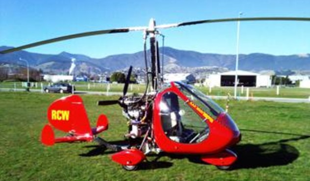
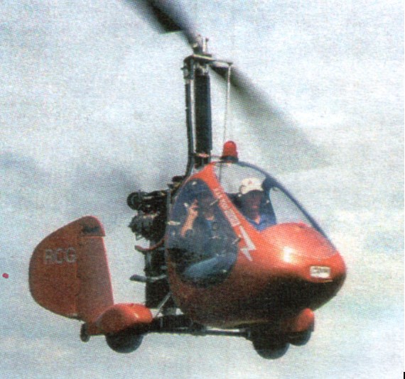
A Canadian-built two seat enclosed frame gyrocopter. Introduced in 1990, the RAF 2000 conforms to 51 per cent homebuilt rules. A conventional autogyro, the 2000 is suitable for training, crop-spraying, power line inspection, predator control, stock mustering and aerial photography. Quoted build time 150-250 hours. The composites RAF rotor blade features 6061-T6 aluminium spar and foam filler, on a patented 5x10cm folding (two-part) rotor mast, with rubber mast bushing and adjustable CG. Removable doors.
The landing gear is tricycle configuration, fixed, with optional speed fairings.
Power is from one 97kW Subaru EJ22 16-valve four-cylinder liquid-cooled engine driving a ground-adjustable three-blade Warp Drive composites propeller through RAF cog belt reduction gear, ratio 2.10:1. Fuel capacity is 87 litres of premium unleaded Mogas, of which 79 litres are usable. Optional capacity 95 litres, of which 87 litres usable. Fuel consumption of the carburated version is 20.1 litres/h, and injected version 18.2 litres/h, both at 80% power.
A pilot and passenger sit side by side in an enclosed cabin. Can be flown with doors removed.
An agricultural version has a 114 litre tank, moulded to fit into the back and bottom of the cabin enclosure, supplying a 24-nozzle spraybar fitted behind and below the engine. Spray width is 6.7 to 7.3m.
Versions include: 2000 STD-SE: Basic version. 2000 GTX-SE: Top-of-range model; kit includes carbureted version of engine, rotor brake, heater, dual controls and adjustable pitch and roll trim assembly. 2000 GTX-SE FI: Fuel-injected version of GTX.
The 2-place rotorcraft is available in kit form. The GTX SE includes a variety of performance enhancing options. Standard engine is a 130 hp four cycle Subaru EJ22. Engine, propeller and instrument packages are included in RAF kits. The airframe is bolted square and round tube aluminium, with shock mounted landing gear.
RAF 2000 GTX SE
The RAF 2000 GTX SE has rough field gear and is powered by a standard Subaru Legacy EJ-22 fuel injected engine (running on avgas) rated at 130 hp. RAF manufacture their own blades with aluminium spars and foam cores covered with composite material. They include a 2 inch strip of Kevlar on the leading edge. The fibreglass rotors fitted to the RAF 2000 GTX-SE are lifed at 500 hours.
Standard features include a cockpit heating system, three point harness, removable doors, a fold down mast, and adjustable centre of gravity provision. The fold down mast reduces the height to 6 foot 6 inch.
At least 500 are believed completed and flown by the end of 2002. 88 were current on the Canadian register in 2002.
COSTS: 2000 STD-SF kit price US$20,615, including Subaru engine (carb version); 2000 GTX-SE US$22,500, including carburated Subaru; 2000 GTX-SE FI US$25,500, including fuel-injected Subaru (all 2003).
Bernard Haseloh holds the first Gyro Pilot’s License issued in Canada and is widely recognized as a pioneer in the gyroplane industry. Mr. Haseloh is highly regarded by Federal Aviation Regulators having for many years served as the designated gyroplane instructor for Alberta, Canada. Bernard Haseloh served as a key technical advisor to the development, testing & design of the RAF 2000
1987 the Group forms Rotary Air Force Marketing Inc, First aircraft to go into production is the RAF 1000, recognizing the need for proper flight instruction and to meet the demand for a two place gyroplane the Rotary Air Force team introduces the Two place Gyroplane in 1989.
A single seat enclosed gyrocopter. Engine: 130 hp EA82 or EJ22 Subaru. Pre-rotator spins up to 350 rpm. Airframe is bolted square and round tube aluminium. Shock mounted landing gear.
Engine: Subaru EA-82 HP range: 100-130 Prop: 60” x 13o Warp Drive 3 blade composite Rotor blades: 28’ RAF composite. Height: 8 ft Length: 12.16 ft Disk span: 25 ft Disk area: 555.7 sq.ft Fuel cap: 12 USG Weight empty: 460 lb Gross: 1125 lb Speed max: 115 mph Cruise: 80 mph ROC: 1000 fpm Take-off dist: 150 ft Landing dist: 1-10 ft Seats: 1 Landing gear: nose wheel
Mr. Haseloh has logged more than 2000 hours of flying time on his experimental “HASELOH” designed machines and has spent over 10,000 hours in the development of prototype gyroplanes of “ THE TYPE “ manufactured and sold by Rotary Air Force South Africa.
First Haseloh built gyroplane, 1954
Two place development, late 1970s.
1970 protptype with two part mast, and CW mounted shock mounted cheek plates.
The origins of Rotary Air Force South Africa. date back to 1943 when Bernard J. Haseloh hovered his first experimental helicopter at his shop in Ponoka, Alberta , Canada.
Mr. Haseloh was discouraged from building and testing amateur/experimental built helicopters, by the Government who felt that the technology for the power driven rotor system was too complex for the private individual.
To further complicate matters, at that time the Government had no regulations in place for amateur/experimental built helicopters.
Haseloh did have an experimental helicopter hovering in 1943.