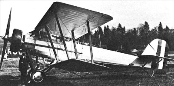
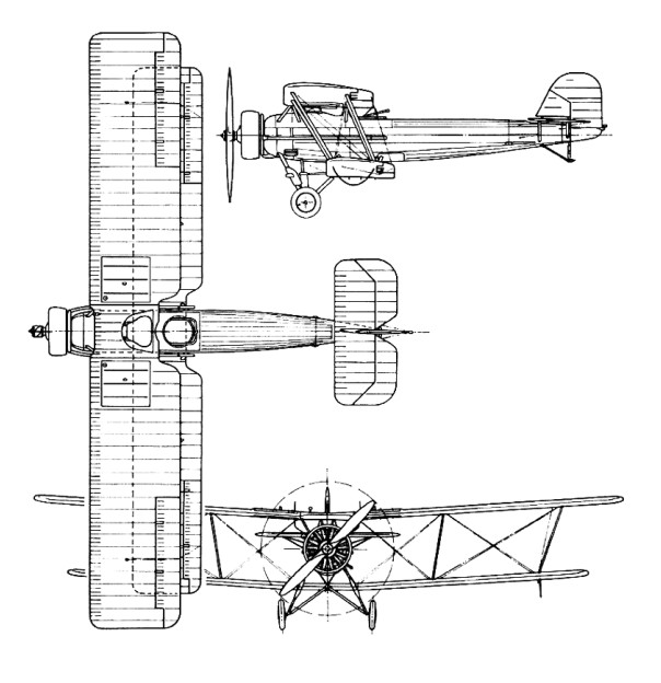
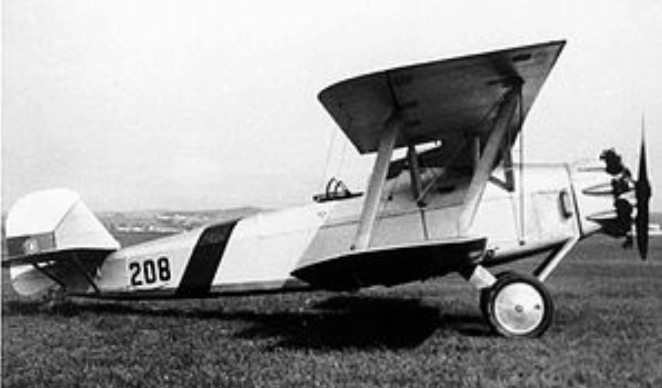
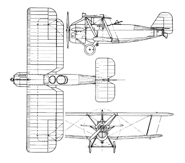
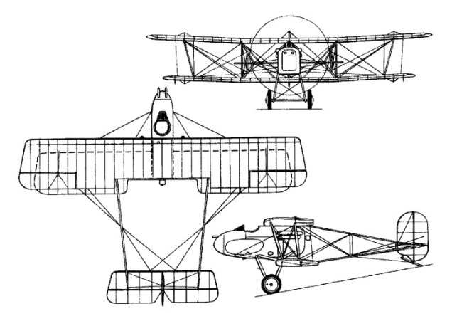
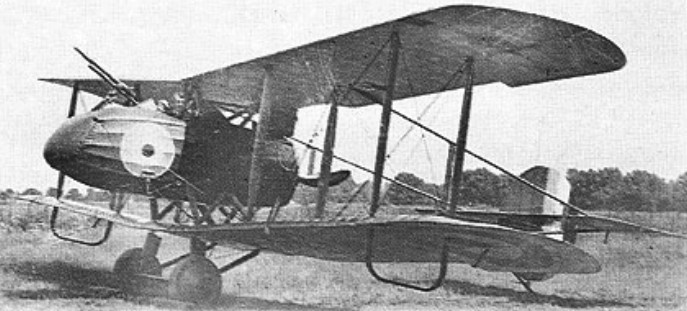
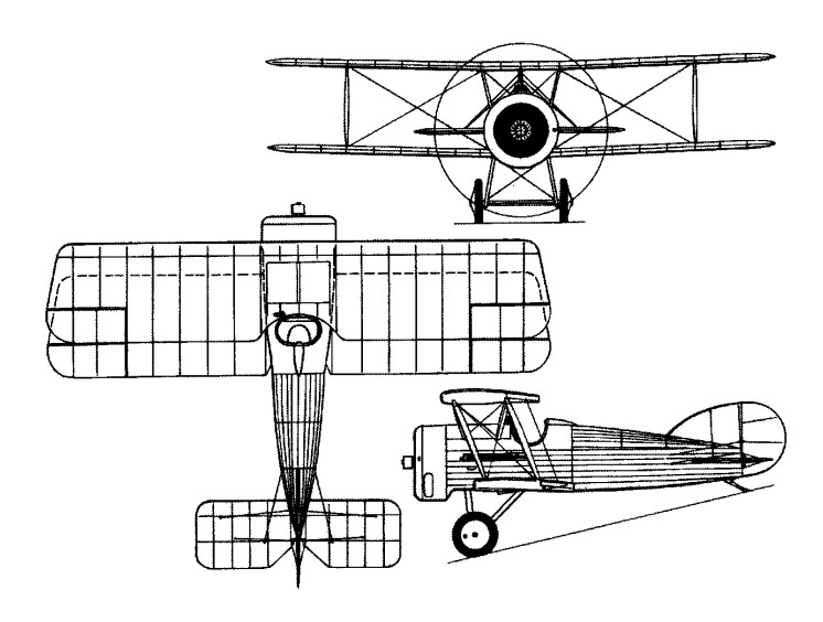
The Vickers Type 113 Vespa Mk I first flown in September 1925 was built as a private venture to the requirements of Air Ministry Specification 30/24 for an army cooperation aircraft. An unequal-span well-staggered biplane with tandem open cockpits, it was powered as first flown by a Bristol Jupiter IV radial; the Vespa was underpowered with this engine, which was then replaced by a 339kW Jupiter VI. After being damaged in an accident during June 1926 it was rebuilt with wings of metal basic structure and redesignated Type 119 Vespa Mk II but, although tested successfully, it was not ordered for the RAF. However, six Type 149 Vespa Mk III aircraft with a number of airframe refinements were supplied to Bolivia during 1929, in which year four aircraft with 365kW Armstrong Siddeley Jaguar VIC engines were ordered for the Irish Army Air Corps and designated Type 193 Vespa Mk IV, four more aircraft with some improvements subsequently being built for Ireland as the Type 208 Vespa Mk V.
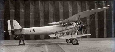
Vickers Type 208 Vespa V, serial V8, delivered to Baldonnel 5 April 1931 and written-off 12 June 1940.
During 1930 the Vespa Mk II was modified to a standard similar to the Irish Vespa Mk IVs and, powered by a 395kW Bristol Jupiter VIIF engine, became designated Type 210 Vespa Mk VI. It was used for demonstrations in China, but on return to the UK was modified yet again, and with a Bristol Pegasus ‘S’ supercharged engine installed was redesignated Type 250 Vespa Mk VII, being used on 16 September 1932 to establish a new world altitude record of 13404m. Following that it was acquired by the Air Ministry and used by the RAE for high-altitude research.
Vickers Type 208 Vespa V, serial V8, delivered to Baldonnel 5 April 1931 and written-off 12 June 1940.
Engine: 1 x 400hp Bristol Jupiter IV Empty weight: 1120 kg / 2469 lb Wingspan: 15.24 m /50 ft 0 in Length: 9.53 m / 31 ft 3 in Height: 3.12 m / 10 ft 3 in Wing area: 52.12 sq.m / 561.01 sq ft Max. speed: 203 km/h / 126 mph Ceiling: 6187 m / 20300 ft Crew: 2 Armament: 2 x 7.7mm machine-guns
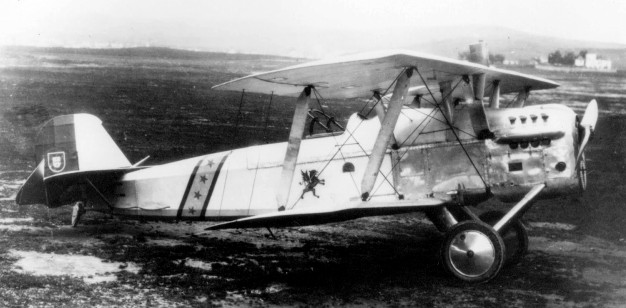
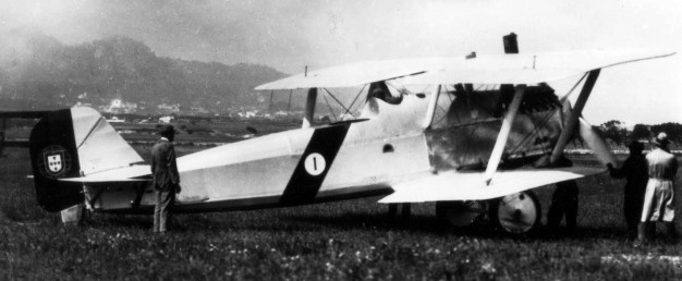
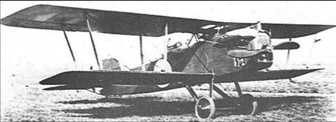
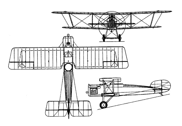
The Vickers Valparaiso was a British light bomber biplane of the 1920s. It was designed by Vickers as a development of its Vixen for export. It was renamed Valparaiso to distinguish it from the Vixen, which as it used classified government equipment, was unavailable for export. Two versions were available, one powered by the same Napier Lion as the Vixen, known as the Type 93 Valparaiso I, while the Type 92 Valparaiso II was powered by the Rolls-Royce Eagle engine. Other than their engines, the Valparaisos were very similar to the Vixen I, both being single-bay biplanes with wooden wings and steel tube fuselages. Both versions were purchased by Portugal, who ordered 10 Valparaiso Is and four Valparaiso IIs, with the Lion-powered aircraft to serve as reconnaissance bombers and the lower powered Valpariso IIs to serve as advanced trainers. In 1928, Portugal decided to license produce a modified Valparaiso powered by a Gnome et Rhône Jupiter radial engine, and a single Valparaiso was modified by Vickers to use the Jupiter, followed by the production of 13 aircraft, designated Type 168 Valparaiso III by OGMA (Oficinas Gerais de Material Aeronáutico).
Valparaiso II
The Portuguese aircraft proved to be successful in service, with two carrying out a long distance tour from Portugal to its African colonies of Angola and Mozambique and back in 1928, with the success of the aircraft resulting in the decision to license produce the Valparaiso III. The radial-powered Valparaisos also proved successful in Portuguese service, remaining operational until 1943, finally being replaced by Westland Lysanders.
A single Valparaiso I (actually the prototype), was sold by Vickers to Chile in 1924. It was successful in Chilean service, resulting in an order for a further 18 modified aircraft, which reverted to the original name of Vixen, as the Vixen V.
Valparaiso III
Variants:
Type 93 Valparaiso I Napier Lion-powered export version of Vickers Vixen. 11 built.
Type 92 Valparaiso II Rolls-Royce Eagle-powered version. Four built.
Type 168 Valparaiso III Version powered by Jupiter radial for Portugal. 13 licensed built by OGMA.
Operators: Chilean Air Force Aeronáutica Militar (Portuguese Army Aviation)
Valparaiso I Engine: 1 × Napier Lion IA 12-cylinder water-cooled W-block, 468 hp (349 kW) Length: 29 ft 0 in (8.84 m) Wingspan: 40 ft 0 in (12.20 m) Height: 11 ft 8 in (3.56 m) Wing area: 526 sq.ft (48.9 sq.m) Empty weight: 3,128 lb (1,422 kg) Loaded weight: 4,720 lb (2,145 kg) Maximum speed: 118 kn (136 mph, 219 km/h) at 10,000 ft (3,050 m) Cruise speed: 96 kn (110 mph, 177 km/h) Range: 478 nmi (550 mi, 886 km) Service ceiling: 19,500 ft (5,950 m) Rate of climb: 951 ft/min [8] (4.8 m/s) Wing loading: 8.97 lb/sq.ft (43.9 kg/sq.m) Power/mass: 0.099 hp/lb (0.16 kW/kg) Climb to 10,000 ft (3,050 m): 10 min 15 sec Armament: 2 × forward-firing .303 in (7.7 mm) Vickers machine gun 1 × .303 in (7.7 mm) Lewis Gun in observers cockpit Crew: Two
A single Valparaiso I (actually the prototype), was sold by Vickers to Chile in 1924. It was successful in Chilean service, resulting in an order for a further 18 modified aircraft, which reverted to the original name of Vixen, as the Vixen V.
71 Vixen I Engine: 1 x 450hp Napier Lion I Max take-off weight: 2143 kg / 4725 lb Empty weight: 1406 kg / 3100 lb Wingspan: 12.19 m / 40 ft 0 in Length: 8.84 m / 29 ft 0 in Height: 3.96 m / 13 ft 0 in Wing area: 48.87 sq.m / 526.03 sq ft Max. speed: 221 km/h / 137 mph Ceiling: 5913 m / 19400 ft Crew: 2 Armament: 2-3 x 7.7mm machine-guns Bombload: 227kg
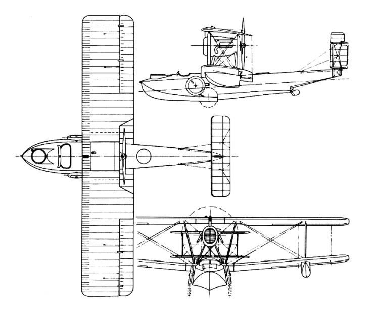
During 1918 Vickers designed a light amphibian with biplane wings and tail unit, its Consuta plywood hull being built by the company’s S. E. Saunders subsidiary and incorporating an enclosed cabin seating four passengers. Its powerplant, a 205kW Rolls-Royce Falcon, was strut-mounted below the upper wing to drive a pusher propeller. Designated Vickers Viking, it was flown for the first time in late 1919. It was in a forced landing with this aircraft, on 18 December 1919, that the company’s famous chief pilot, Sir John Alcock, was killed.
From this Viking I was developed a series of aircraft with progressive improvements, especially to the hull (some of which had open cockpits), and differing powerplant. They comprised the one-off Viking II (268kW Rolls-Royce Eagle VIII) and Viking III (336kW Napier Lion), followed by the production Type 54 Viking IV. Of the 26 that were sold, examples in several type numbers went to the armed services of Argentina, Canada, France, Japan and the Netherlands, and for civil use in Argentina, Canada, the Soviet Union and the USA. Ironically, Sir Ross Smith, knighted like Sir John Alcock for a Vickers Vimy pioneering flight, was killed in an accident with a Viking IV on 13 April 1922. The final version was the Viking V with Napier Lion engine, two built for service with the RAF in Iraq.
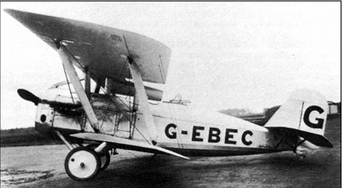
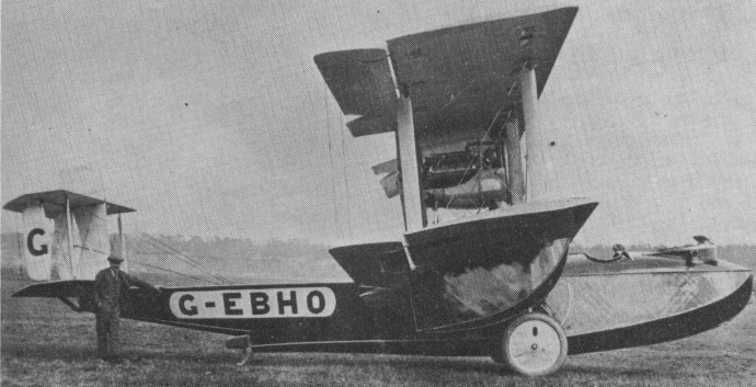
The aircraft that was to have been the Viking VI, with redesigned wing structure and single 450 HP Napier Lion engine with a four blade pusher propellor, was designated Type 78 Vulture I; a second example with a 268kW Rolls-Royce Eagle IX had the designation Type 95 Vulture II but was later re-engined with a Napier Lion. These two aircraft were used during 1924 in an unsuccessful round-the-world flight attempt.
The Vickers Type 95 Vulture, G EBHO, was registered to Vickers Ltd on August 9, 1923. It was a three seat amphibian powered by a single 450 hp Napier Lion and was one of two designed by R. K. Pierson for Sqn Ldr A. C. S. MacLaren’s round the world flight. This attempt began at Calshot on March 25, 1924, and ended with a take off crash at Akyab, Burma.
On May 24 the other aircraft, G EBGO, was shipped to Akyab from Tokyo, where it had been positioned earlier, to continue the flight. This also ended prematurely with a forced landing in heavy seas near the Aleutian Islands on August 2, 1924.
Last of the Viking series, at first designated Viking VII but later named Type 83 Vanellus, was a single aircraft for evaluation by the RAF as a three-seat (pilot, observer/gunner and gunner) open-cockpit fleet-spotter; it differed primarily from its predecessors by having a monoplane tail unit. The 15.24m span Viking IV with Napier Lion powerplant had a maximum speed of 182km/h at sea level.
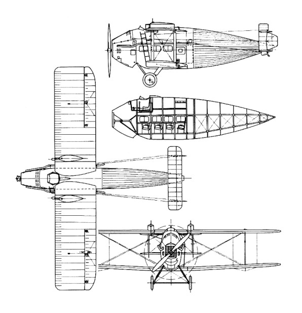
In early 1921 design was initiated of the Vickers Vulcan transport, a biplane of 14.94m span with a deep oval-section fuselage completely filling the space between the equal-span wings. It accommodated the pilot in an open cockpit forward of the upper wing, with below and behind him a roomy enclosed cabin for six to eight passengers. To limit selling price to the minimum, the low-cost war-surplus 268kW Rolls-Royce Eagle VIII engine was installed in the first six aircraft (Type 61) to be completed, but as a number of performance problems were encountered the last two examples (Type 74) had the 336kW Napier Lion. One of the early production aircraft was completed as a cargo carrier (Type 63) for Air Ministry evaluation, but was subsequently reconverted as a passenger carrier and used with one other Eagle-powered and the two Napier Lion-powered aircraft by Imperial Airways on European service. Their very limited reliability meant the Vulcan had a short useful life, only one or two surviving in service beyond the mid-1920s.
Type 74 Engine: 1 x Napier Lion, 336kW Max take-off weight: 3062 kg / 6751 lb Wingspan: 14.94 m / 49 ft 0 in Max. speed: 180 km/h / 112 mph Passengers: 6-8
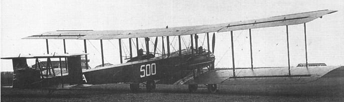
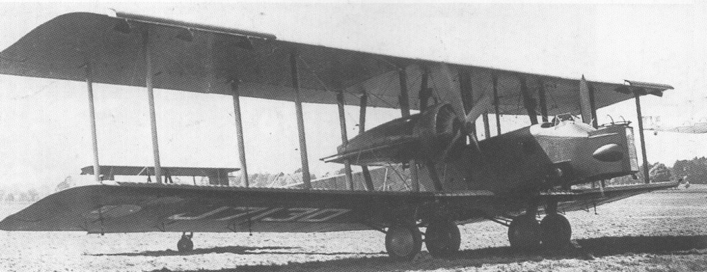
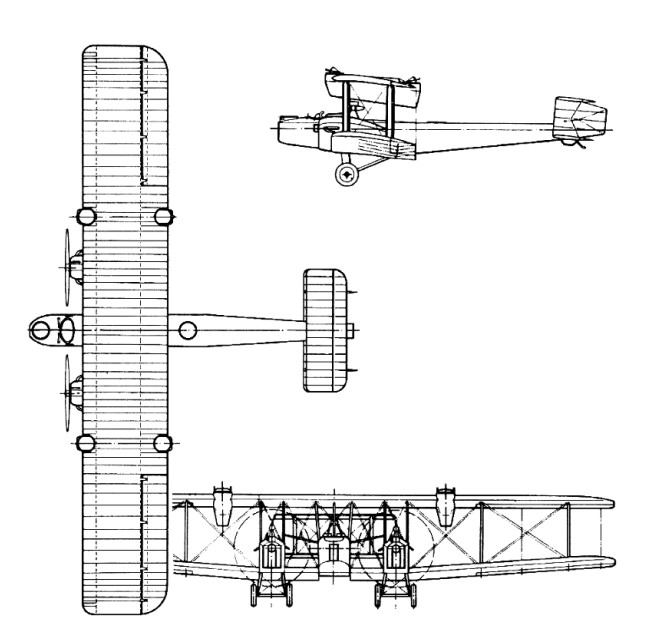
Designed to meet the requirements of Air Ministry Specification 1/21, two aircraft were ordered initially, designated Virginia I and Virginia II. The former was the first to fly (on 24 November 1922), powered by two 335kW Napier Lion engines. It was basically an enlarged version of the Vickers Vimy, but had its Napier Lion engines mounted on the lower wings and enclosed in rectangular nacelles. Construction was mainly of wood and fabric with a fairly extensive amount of wire bracing. The second Virginia differed by having close-fitting engine cowlings; a Lamblin cooling radiator mounted between the landing-gear legs; a lengthened nose to provide more room for the bomb-aimer and, for the same reason, a slight decrease in intended bomb load; and a variable-incidence tailplane which could be adjusted in flight.
The Virginia prototype first flew on 24 November 1922 but initially both the Virginias were unstable in flight, leading to modifications which included dihedral on both wings instead of on the lower wing only, introduction of larger rudders, an additional fin, and re-siting of the engines further forward.
The first production contract was for two Virginia Mk.III aircraft, generally similar to the Virginia II but provided with dual controls and changes in armament. Like the earlier prototypes, these were subsequently modified to later standards. Four additional aircraft were ordered in 1923. Power plant comprised two 349kW Napier Lion Series II engines. Again, these aircraft were later updated, being fitted with metal wings, and ended their lives as Mk.Xs.
The type began to enter service as the Virginia Mk III, replacing the Vimy bombers of Nos 7 and 58 Squadrons, the first of eight regular and two auxiliary squadrons to operate the type.
The two Virginia Mk.IVs differed in electrical equipment and bomb load. First major production version (22 built) was the Mk.V, which had a third rudder, first test-flown on a Mk.IV aircraft; otherwise these aircraft were generally similar to the Mk.III. They were modified subsequently to later marks. The Mks III to VI had dihedral on the lower wings and unswept outer wings. Interestingly, Vimys were still being delivered at this time.
The Virginia Mk.VI (25 built) was the first production version to include dihedral on both upper and lower wings as standard; design of the wing-folding mechanism was improved. It was followed by 11 Mk.VIIs, which introduced still further changes to improve stability – including introduction of Frise ailerons and sweepback on both wings. These represented such an improvement in flight characteristics that many earlier aircraft were modified subsequently to this Mk.VII standard.
To provide adequate defence for these large and comparatively slow bombers there had been a number of experiments to locate gunners in ‘fighting tops’ – nacelles attached to the trailing edge of the upper wing. Apart from the aerodynamic problems, the gunners suffered from the cold and it was decided to introduce instead a gunner’s position at the tail-end of the fuselage. This involved not only modification of the rear fuselage but increased tailplane span and a leng-thened nose to maintain good stability. These aircraft (eight built) became designated Mk.IX and some earlier aircraft were converted subsequently to this standard. Final version was the Mk.X, which introduced a metal structure with fabric covering and introduced leading-edge slats and a tailwheel in place of the, original skid (50 built). A large number of earlier aircraft were converted to include the more powerful engines, hydraulic wheel brakes, landing lights, and auto pilot which distinguished this, the last of the series.
Total production of the Virginia series was 124, the type finally replaced as a bomber by the Heyford and Whitley in 1937, surviving aircraft being relegated to parachute training for four more years.
Virginia Mk X Type: four-seat heavy night bomber Powerplant: 2 x Napier Lion V, 425kW (570 hp) Span: 26.72m (87ft 8in) Length: 18.97m (62ft 2.75 in) Height: 5.54 m / 18 ft 2 in Wing area: 202.34 sq.m / 2177.97 sq ft Armament: 3 x 7.7-mm (0.303-in) machine-guns Bombload: 1452 kg (3,200 lb) internal Empty weight: 4377 kg / 9650 lb Max T/O weight: 7983 kg (17,600 lb) Max speed: 174 km/h / 108 mph at 4,920ft Operational range: 985 miles / 1585 km Ceiling: 4725 m / 15500 ft
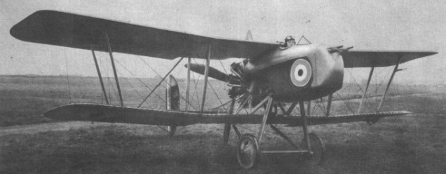
Curiously retrogressive in design when built in May 1917, the pusher fighter with boom-carried empennage being decidedly passe at that stage in Worid War I, the F.B.26 single-seat fighter had its nacelle attached directly to the upper wing. The original concept provided for a single 7.7mm Lewis gun, but an additional Lewis had been introduced by the time that the F.B.26 reached Martlesham Heath for official testing in July 1917.
Power was provided by a 200hp Hispano-Suiza engine, but inadequate cooling led to the original single flat radiator being replaced by two separate radiator blocks. On 25 August 1917, the prototype was spun into the ground by Vickers’ test pilot Harold Barnwell. Nonetheless, a month later, on 19 September, a contract was placed for six examples of a modified version of the F.B.26. The wing structure was completely revised, radiator blocks were attached to the nacelle sides and a larger vertical tail was introduced. Interest in the F.B.26 centred on its potential as a Home Defence fighter, and it was proposed that armament would consist of two Lewis guns coupled with an Aldis sight and capable of several degrees of elevation and depression. However, in order to obtain greater firepower, the nacelle of the F.B.26 was modified to permit installation of an Eeman three-gun universal mounting. The first two F.B.26s had the trio of Lewis guns fixed to fire horizontally, but it was intended that the next four aircraft would have a modified Eeman mounting capable of 45° of elevation.
The first of the modified F.B.26s was flown in December 1917 with a 200hp Hispano-Suiza engine. After testing at Martlesham Heath, this aircraft was assigned to No 141 Sqn in February 1918 for service evaluation. It was concluded that the F.B.26 was unsuited for Home Defence duties and work on the incomplete machines was halted, although the second and third examples had been completed and flown meanwhile. As the basic design was considered to possess potential in the close air support role, the second of the modified F.B.26s was fitted with a redesigned nacelle incorporating armour protection for the pilot and a 230 hp Bentley B.R.2 nine-cylinder rotary. This armoured “trench-strafer” was assigned the designation F.B.26A, and, under the official nomenclature scheme introduced in the spring of 1918, became the Vampire II, the F.B.26 being the Vampire I. In the event, the Vampire II had still to be completed by the end of June 1918, and thus came too late on the wartime scene.
Max take-off weight: 921 kg / 2030 lb Empty weight: 667 kg / 1470 lb Wingspan: 9.63 m / 32 ft 7 in Length: 7.14 m / 23 ft 5 in Height: 2.87 m / 9 ft 5 in Wing area: 24.80 sq.m / 266.94 sq ft Max. speed: 195 km/h / 121 mph Ceiling: 6860 m / 22500 ft
Derived from the abortive F.B.23 design intended as a successor to the F.B.9, the F.B.25 two-seat night fighter was conceived to fulfil the same requirement as the Royal Aircraft Factory’s N.E.1. Completed in the early spring of 1917, the F.B.25 carried its two crew members in staggered side-by-side seats, the gunner being positioned ahead and to starboard. Like the N.E.1, the F.B.25 was intended to carry the Vickers-built Crayford rocket gun with which it was supposed to attack hostile airships, and a small searchlight was originally to have been mounted in the extreme nose of the nacelle. The intention was to power the F.B.25 with the 200hp Hispano-Suiza eight-cylinder water-cooled engine, and in order to minimise the risk of the aircraft turning over during a nocturnal landing, it was proposed to provide a nosewheel. In the event, non-availability of a 200hp unit dictated installation of a 150hp Hispano-Suiza, and neither searchlight nor nosewheel was fitted. A two-bay unstaggered equi-span biplane with tailbooms converging in elevation to meet at the rear spar of the tailplane, the F.B.25 carried its unusually wide nacelle at mid wing-gap. As well as the Crayford rocket gun, an interesting feature was the oleo-pneumatic undercarriage. Flight testing revealed poor characteristics, and when sent to Martlesham Heath in May 1917 (where it was eventually to crash), the official reports were singularly unflattering, dismissing the F.B.25 as wholly unsuited for night fighting.
Max take-off weight: 1113 kg / 2454 lb Empty weight: 729 kg / 1607 lb Wingspan: 12.65 m / 42 ft 6 in Length: 8.56 m / 28 ft 1 in Height: 3.30 m / 11 ft 10 in Wing area: 46.45 sq.m / 499.98 sq ft Max. speed: 138 km/h / 86 mph Ceiling: 3355 m / 11000 ft
A two-seat fighter-reconnaissance aircraft, the F.B.24 was yet another Vickers aircraft originally designed for the ill-fated and Vickers-sponsored Hart radial engine. The prototype was completed in December 1916, but unavailability of the Hart engine resulted in its modification to accept the 150hp Hispano-Suiza water-cooled engine as the F.B.24A, and the second airframe, the F.B.24B, being similarly powered. An unequal-span two-bay biplane, the F.B.24 had an armament of one fixed synchronised Vickers gun and one Lewis on a Scarff ring mounting. Both F.B.24A and 24B were re-engined with the 200hp Hispano-Suiza with which they were redesignated as F.B.24Ds. Similar in general configuration was the F.B.24C, which was powered by a 275hp Lorraine-Dietrich 8Bd water-cooled eight-cylinder Vee-type engine and armed with two synchronised Vickers guns, provision being made for emergency dual control in the gunner’s cockpit. The F.B.24C and D both possessed good performance, but the limited view offered from the pilot’s cockpit was considered unacceptable. Consequently, the Vickers team revised the basic design by lowering the upper wing so that it was attached directly to the upper longerons, the front cockpit being situated between the wing spars. With this change, the aircraft was de signated F.B.24E and power was provided by a 200hp Hispano-Suiza. This same configuration was adopted for yet a further version of the design, the F.B.24G, which was a larger aircraft than its predecessors, with two-bay wings of equal span and chord and a 375hp Lorraine-Dietrich 12-cylinder Vee-type engine. The F.B.24G was built in France by the Darracq concern, but it did not fly until 26 May 1919, and its performance and fate have gone unrecorded.
F.B.24D Empty weight: 739 kg / 1629 lb Wingspan: 10.82 m / 36 ft 6 in Length: 7.92 m / 26 ft 0 in Wing area: 31.59 sq.m / 340.03 sq ft Max. speed: 190 km/h / 118 mph
Designed in 1916 by G H Challenger and flown for the first time in August of that year, the F.B.19 was a single-bay unstaggered equi-span biplane with a single 7.7mm Vickers gun mounted on the port side of the fuselage and a 100hp Gnome Monosoupape engine. Ordered by the War Office for the RFC, the series version was powered by either the Gnome or the 110hp Le Rhone. Some 50 F.B.19s were built, and, late in 1916, a batch of six was sent to France where, after operational evaluation, the fighter was deemed un-suited for the fighting conditions then evolving. At this time, some of the F.B.19s were delivered to the Russian government following demonstrations in Petrograd, Moscow, Kiev and Tiflis, but several were still in their crates on the docks at Archangel at the commencement of the Bolshevik revolution. These aircraft were destroyed by the Royal Navy, but a few others assembled prior to the Navy’s action were flown in Bolshevik service. A modified version, the F.B.19 Mk II, was developed with wing stagger and either the Le Rhone or Clerget 110hp rotary. Only 12 Mk IIs were built and several of these were included in a batch of 12 F.B.19s sent to the Middle Eastern theatres of war. These were flown in Palestine and Macedonia from June 1917, but no squadron used the type exclusively and it was not well liked.
F.B.19 Engine: 1 x Gnome Monosoupape, 75kW Max take-off weight: 670 kg / 1477 lb Empty weight: 405 kg / 893 lb Wingspan: 7.31 m / 24 ft 0 in Length: 5.54 m / 18 ft 2 in Height: 2.51 m / 8 ft 3 in Wing area: 19.97 sq.m / 214.96 sq ft Max. speed: 158 km/h / 98 mph Ceiling: 5180 m / 17000 ft