Constructed at the Republic of Korea Chinhae Naval Shipyard in 1957, the then un-named flying boat was of mixed metal and wood construction. Power was two 213 hp Continental 0-470-11 engines.
Constructed at the Republic of Korea Chinhae Naval Shipyard in 1957, the then un-named flying boat was of mixed metal and wood construction. Power was two 213 hp Continental 0-470-11 engines.
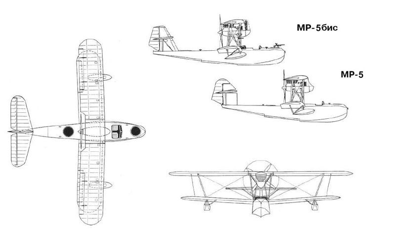
The Grigorovich MR-5 flying boat was built at Factory No.22 and in the summer of 1929 it was sent to Taganrog for testing. During its development it was found that the hull behaved correctly in the water, but during takeoff operations a large curtain of water formed in front of the plane, which made the process difficult. The take-off run distance was also getting too long. The commission that studied the possible destiny of the model concluded on December 1, 1929, that the problems were due to a bad design of the bow section of the hull.
Grigorovich had been arrested, so trying to save the model, the development was transferred at the beginning of 1930 to the construction bureau OPO-4, directed by the Frenchman Paul Aimé Richard . The development was included in the KB ‘s work plan for the year, but very little attention was paid there to improving one design created by another, so finally, at the time of Richard ‘s departure from the USSR , the MR-5 had received no attention.
The need for reconnaissance flying boats was great so in 1931 the MR-5 was delivered to the new TsKB of Factory No.39, where the head of the naval department IV Chetverikov was in charge of the modifications to achieve better behavior in the water.
For this purpose Chetverikov decided to build a new wooden hull with better lines and the empennage underwent modifications, increasing its area. The new model was numbered 10 within the TsKB designations, but was generally known as the Chetverikov MR-5bis (Russian: Четвериков МР-5бис/ЦКБ-10).
In January 1932 Chetverikov read a report that the tests of the TsKB-10 had started, but at that time it referred only to the tests on skis. The complete cycle of tests was completed by the summer of 1932, being developed in the section of the Moscow River where the Gorky Central Park of Culture and Rest (TsPKO) is located today.
In these tests, the hull behaved positively, noting a noticeable decrease in splashes. Despite this, the long-awaited serial production was not approved. The Italian Savoia S-62 flying boat, which had entered service with the VVS RKKA under the designation MR-4, was successfully produced in the Taganrog workshops. Only the on MR-5bis was built.
The MR-5bis differed fundamentally from the original model in its new hull
In some sources Grigorovich ‘s original model has been named as MR-3 and Chetverikov’s version as MR-3bis. This presumably constitutes an error, which has become widespread on multiple sites on the internet that reference these sources. The searches carried out by the Soviet researcher M. Maslov in the original documents of the time show that the term MR-3 was used only to designate the reconnaissance flying boat ROM-1 and MR-3bis designated the improved version ROM-2.
Type: MR-5bis
Powerplant: 1 x 680/500 hp M-17
Wingspan: 15.60m
Wing area: 53.00 m²
Length: 11.40m
Empty weight: 2050kg
Maximum takeoff weight: 3100 kg
Wing loading: 59.0 kg/m²
Power Load: 6.2kg/hp
Fuel + oil load: 440+30 kg
Full load capacity: 1050kg
Top speed: 190km/h
Cruising speed: 162km/h
Landing speed: 85km/h
Practical range: 720 km
Endurance: 4 hours
Practical ceiling: 4000 m
Landing Time: 22s
Take off time: 35s
Accommodation: 2
Three prototypes of the eight-passenger TA-1 flying-boat were completed in 1947.
As early as 1933, while still working at OSGA, Chetverikov had begun the development of a hydrofoil designed to patrol the Arctic areas. As there was no defined technical task, Chetverikov set the goal of obtaining a speed of 300 km / h and a range of 3000 km. Around 1936 the GlavsievMorPuti became interested in this development and decided to contract Chetverikov for its construction. This event marked the emergence of the ARK-3. The objective of the model was Arctic exploration and patrol, liaison with ships, and the transfer of personnel and assets north.
Chetverikov received the necessary funds for development, the allocation of his own production base in Sevastopol and a major change of subordination, moving from the civil structure of the GVF to work under the direction of the State Directorate for the Aeronautical Industry (GUAP).
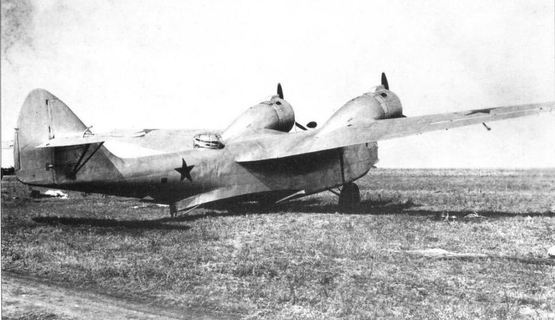
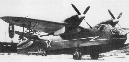
The Chyetverikov ARK-3 (ARKtichyeskii – arctic) was a multi-role flying boat designed for Arctic operations. It featured a conventional flying boat hull, with high cantilever wings equipped with floats at mid-span. The two piston engines were mounted in tractor-pusher fashion on a pylon above the fuselage.
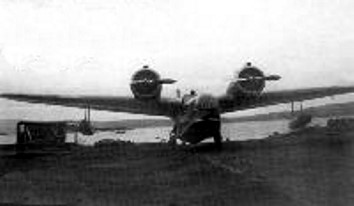
The ARK-3 was designed as a cantilever high-wing hydrofoil with two Shvetsov M-25 635 hp engines installed in tandem on a pylon located in the center, braced by struts, which were later replaced by rigid uprights. The two engines powered variable pitch VISh (Hamilton Standard) propellers.
The ARK-3 was of mixed construction, with a 14-metre (45.9 ft) long Duralumin stressed skin fuselage; wooden wings of MOS-27 aerofoil section and set at 5° angle; duralumin tubing tail surfaces; and ailerons with fabric covering. The dual control enclosed cockpit housed two pilots sided by side with two gunners/observers in bow and dorsal positions where a 7.62 mm machine gun could be installed. In the first prototype built these areas were simply left open. The second prototype built installed turrets in both positions. Strut-supported wooden floats, at approximately half-span; and a pylon-supported engine nacelle housing tandem radial engines with Townend ring cowlings; completed the structural elements, built with a safety factor of 5.5.
At the beginning of 1936, the construction of the first АРК-3 prototype was finished in Sevastopol Factory No.45, which was tested in the summer of that year, showing quite acceptable results. The tests culminated in September, achieving a speed at sea level of 252 km / h and 2600 meters reached 308 km / h. The flight ceiling was above 7600 meters. Shortcomings were also highlighted: poor design of the bow splash deflectors, weakness in the powertrain. Even a small 0.25 meter wave ran across the entire bow in front of the cockpit and the splashes reached the propellers.
This was considered to be due to the short length of the bow and its narrow width of only 1.7 meters. There were hardly any problems for take-off, but during the landing on the water there were commonly waves that swept over the bow.
Performance was deemed to be good, prompting an order for a second prototype with the fuselage lengthened by 60 centimetres (24 in) to 14.6 metres (47.9 ft) and a slightly enlarged wing chord; this was designated ARK-3-2 and the first prototype was re-designated ARK-3-1 or MP-2 (Mosrkoi Passazhirski or Naval Passenger Transport). The second prototype ARK-3 featured more powerful engines, longer hull, and manual guns fitted in a manual gun turret in the bows and a dorsal sliding hatch. The APK-3/2, already equipped with weapons, was released in May 1938 with two M-25A engines. The weight of this model increased by 400 kg. A production order for five aircraft was placed, with production commencing immediately.
This first model was modified in order to eliminate the defects indicated. Splashes were considerably reduced with the installation of deflector blades forward. The fastening straps of the driving nacelle were replaced by rigid supports.
On 25 April 1937 Russian pilot A.V. Erchov reached a height of 9160 meters with a payload of 1000 kg in the Crimea with a Chetnerikov A.R.K. 3 twin-engine flying boat, so he surpassed the existing world record, which was still held by the Frenchman Bourdin, who took off in 1933 with a load of 1000 kg 8864 m high.
On 14 July 1937 the ARK-3-1 was destroyed following a structural failure when after a sudden landing the engine fell forward causing the death of the pilot; the ARK-3-2 lost its tail in flight and was destroyed exactly one year later.
At that time, five other copies were found in a different state of completion in addition to the prototypes, and the programme was cancelled.
The ARK-3 formed the basis for the MDR-6 (Che-2) hydrocanoa.
ARK-3-1 / MP-2
The first prototype ARK-3 renamed after the second prototype was ordered
Engines: 2 x M-25, 710 hp takeoff / 630 nominal hp
Wingspan: 20.00 m
Length: 14.60 m
Wing area: 59.5 m²
Wing profile: MOS-27
Empty weight: 3,242 kg
Normal takeoff weight: 4787 kg
Overloaded weight: 5800 kg
Oil weight: 150 kg
Fuel weight: 870 kg
Total load capacity: 1545 kg
Wing loading: 83 kg / m²
Power load: 3.4kg / hp
Maximum speed at sea level: 252 km / h
Maximum speed at 2,600 meters: 308 km / h
Landing speed: 105 km / h
Practical ceiling: 7600 m
Range: 3000 km
Endurance: 7 hours
Ascent time to:
1000 m – 3.5 min
2000 m – 7.0 min
3000 m – 10.0 min
4000 m – 14.0 min
5000 m – 18 min
Accommodation: 3
ARK-3-2
The second prototype ARK-3.
Engine: 2 × Shvetsov M-25A, 544.36 kW (730 hp) takeoff / 650 hp nominal
Wingspan: 20 m (65 ft 7-1/4 in)
Wing area: 59.5 m2 (640 ft2)
Length: 14.6 m (47 ft 11 in)
Empty weight: 3,642 kg (8,029 lb)
Normal takeoff weight: 4787 kg
Overloaded weight: 5800 kg
Fuel weight: 820 kg
Oil weight: 160 kg
Total load capacity: 1958 kg
Wing loading: 94 kg / m²
Power load: 3.8kg / hp
Maximum speed at sea level: 260 km / h
Maximum speed at 2600 m: 320 km/h (199 mph)
Landing speed: 110 km / h
Endurance: 7 hours
Range: 3000 km
Ascent time to:
1000 m – 3.5 min
2000 m – 7.0 min
Service ceiling: 8,500 m (27,890 ft)
Rate of climb: 4.76 m/s (937.4 ft/min)
Crew: 4
Capacity: 10 pax
Armament: 2 x 7.62 mm machine gun
Bombload: 1,100 kg
ARK-3 MP2
Designation of the five production aircraft and the initial designation of the first prototype.
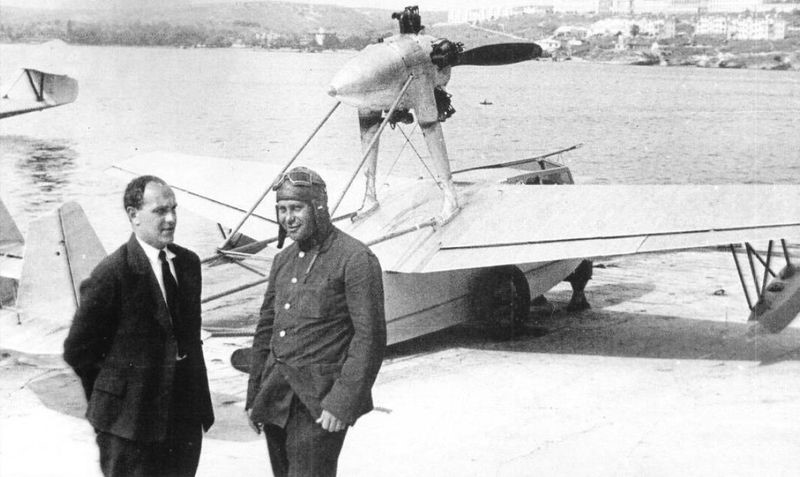
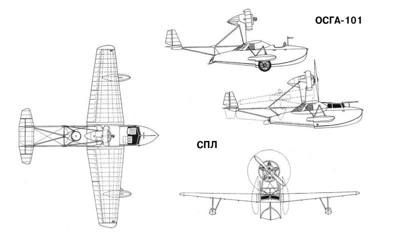
The development of an aircraft to carry out operations from submarines was taken over by IV Chetverikov in 1931. In its design, Chetverikov decided to start from the already proven design used in the OSGA-101 light flying boat. The new model was known as SPL (Russian: Четвериков СПЛ), after the acronym for Samoliet Podvodnoy Lodki or Airplane for submarines.
As fundamental differences, the general dimensions were reduced in order to allow the aircraft to be accommodated in a sealed hangar of only 2.5 x 7.5 meters. Systems were also developed that would allow the wing, the power plant and the stabilizer consoles to be transformed, using quick-action fixing screws instead.
The decision to build a flying boat of minimum dimensions also had its cost. The tail had very little area, so the flying boat had little stability. The visibility of the cabin was poor, especially for the observer, since the crew was forced to position themselves towards the center of gravity of the aircraft in order to reduce the length. To reduce the weight, the flying boat did not have the possibility of carrying any type of armament. The resulting aircraft looked more like a sports competition model than a military aircraft.
The SPL was designed as a high-wing monoplane flying boat. The wing, similar to that used on the OSGA-101, featured a three-spar configuration with a trunk frame and wooden construction. The areas on the outside of the wings between the leading edge and the intermediate spar were covered with plywood. The rest of the wing presented fabric covering, sewn with thread to the ribs.
Unlike the OSGA-101, on the SPL there were no fasteners on the first and third stringers. In this way the force of the support was exerted only on the central beam. In the extended position, the wing was secured by a quick-release fastener located at the top of the center spar. At the bottom was a gimbal that was inserted into a cavity in the centroplane. To pick up the wing, it was enough to release the fixator, rotate the wing console around the axis of the spar and move them towards the sides of the hull.
The SPL wing was designed using the MOS-27 airfoil with a relative thickness of 18% at the root section and 12% at the tips. This fact, together with a considerable narrowing of the wing, made it possible to obtain a break in the flow at the wing tips when operating with large angles of incidence. For this reason, it was enough for the pilot to pull the stick a little hard on landing so that the plane began to dive on the wing. At that time, the phenomenon of wingtip vortices was little studied, so the fault for this behavior was attributed to the poor transverse stability of the model. Attempts were made to cure this problem by increasing the wing’s wing gradient to about 5°, but the effect was nil. According to Chetverikov himself the problem could be compensated thanks to the great effectiveness of the ailerons.
The large-area wings occupied the entire trailing edge of the consoles and featured two sections: an inner or root section and an outer section. The inner sections could be used as flaps during landing. The wings were made of wood and featured fabric-covered box-type spars. The leading edge was covered with plywood.
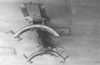
The underwing floats had a wooden structure with frames and braces, covered with plywood. In the SPL, unlike the OSGA-101, the construction of these floats was simplified.
The hull of the SPL was similar to that of the OSGA-101 and featured all-wood construction. The structure had several frames with stringers and braces and plywood sheathing. The hull design demonstrated excellent hydrodynamic qualities, which was necessary for the operation of the model in the open sea. The large angle of the keel reduced the overloads when riding the waves and the high rails ensured a smooth takeoff and landing in tidal conditions.
The three-sided tail beam was made of steel tubes and its rigidity was ensured by means of cable-stayed straps. The control cables for the rudders were routed inside the tubes of the structure. The empennage was built on a fabric-covered welded steel tube structure. The keel spars and stabilizers as well as the ribs and leading edges were constructed from thin steel tubing. Unlike the OSGA-101, in the SPL the stabilizers had a biplane structure in order to reduce their wingspan.
The SPL lacked its own landing gear and for operations on land, removable wheels were used whose axles were fixed to a tube that passed through the hull from side to side.
The power plant selected was the excellent 100 hp M-11 driving a two-bladed, fixed-pitch wooden propeller. This propeller had a diameter of 2.3 meters. Originally, an annular Townend-type hood made of aluminum was installed, but it was soon found that the aerodynamic improvements of its use on the M-11 engine they were not considerable, reason why it was eliminated. The engine was located on a high pile conceived of welded steel tubes and designed to prevent water splashing on the propeller during takeoff and landing operations. To facilitate its packing inside the narrow container, the engine lay down backwards. To achieve this in the SPL the drive location was slightly rearward, the strut could pivot and the rear mount base was moved rearward by the main tail tube. The motor control was carried out by sheathed cables that were collected along with it.
The optimum position on takeoff and landing ensured a wing angle of incidence of 6º, but during flight the optimum angle was 2º. For this reason, in flight, the nose of the flying boat was inclined slightly downwards, while the engine was at that moment totally in line with the flow of navigation.
In the motor gondola there was a 10-liter tank for oil and another 20-liter tank for fuel. The main fuel tanks were located in the hull.
The dimensions of the SPL once folded were only 7.45×2.12×2.35 meters. Flight readiness was achieved in 4-5 minutes and after the mission the wings, tail and engine could be folded in 3-4 minutes.
The SPL was fully painted silver. Originally it had no markings or symbols, but later on its nose and wings, above and below, the characteristic red stars were painted. The Gidro-1 example, which was shown at the Milan fair, featured Aeroflot symbols in blue on both gunwale and lacked the red stars.
The SPL was built in the workshops of the Sled and Hovercraft Building Department (OSGA), subordinate to the NII GVF. The prototype was finished by December 1934 and moved to Sebastopol to carry out sea trials, which were completed on August 29, 1935. Its realization was in charge of the test pilot of Factory No.45 AV Krzhizhevski.
The tests demonstrated the feasibility of the packing and unpacking operation of the aircraft in the submarine in a time of 4-5 minutes, its possible take-off and its effective recovery after the flight. The authors of the project managed to obtain a container only 7.45 meters long and with a diameter of 2.5 meters. In general, the SPL showed acceptable performance in the water, but its seaworthy conditions were not good, especially in the open sea. It was clear that very little more could be asked for an aircraft of this type, but in these conditions the aircraft was not very attractive to the military.
The Gidro-1 next to an MP-1bis with the colors of Aeroflot to participate in the fair in Milan in 1936.
In 1936 the SPL with the Aeroflot symbols and Gridro-1 denomination, participated in the Milan Fair, receiving a positive evaluation.
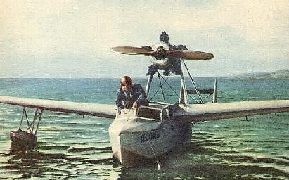
On September 21, 1937, in this plane, the pilot AV KrZhizhevski established a world speed record of 100 km, reaching 170.2 km/h, and on October 7 of that year, he established a new distance record for aircraft of its category. when reaching 480 km and high when setting 5400 meters. Despite these results, the model did not have further development.
Documentary references to a flying boat built by Chetverikov have been found at Sevastopol Factory No.45. It could be a second issue of the SPL, but this is just conjecture.
SPL
Power plant: М-11, 100 hp
Wingspan: 9.6m
Wing area: 13.4 m²
Length: 7.4m
Height: 2.72m
Empty weight: 592kg
Weight with normal load. 800kg
Maximum takeoff weight: 879kg
Fuel weight: 60kg
Oil weight: 10kg
Total load capacity: 208 kg
Wing loading: 59.7 kg/m²
Overloaded wing loading: 65.7 kg/m²
Power load: 8kg/hp
Overloaded power load: 8.8 kg/hp
Maximum speed at sea level: 186 km/h
Cruising speed: 174km/h
Landing speed: 85km/h
Endurance: 2 hours
Range: 480km
Practical ceiling: 5400 m
Time to 1000m: 3.9min
Time to 2000m: 8.7min
Time to 3000m: 15.3min
Time to 4000m: 25.5min
Time to 5000m: 50.0min
Accommodation: 2
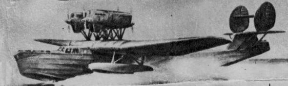
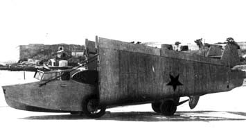
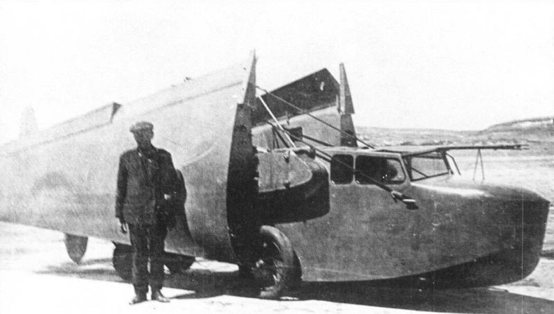
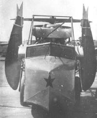
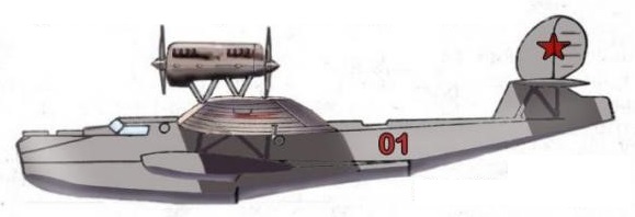
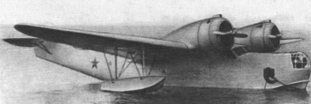
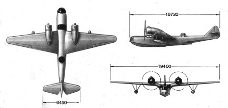
In the experimental construction plan of the naval department of the TsKB a new task of development of a naval reconnaissance flying boat was introduced, which received the 11th number in the row of this institution. Based on its function, the new model was designated MDR-3 or TsKB-11 (Russian: Четвериков МДР-3 (ЦКБ-11)), according to the acronym for Morskoi Dalni Razvietchik or Long-Range Maritime Reconnaissance Aircraft.
The department, under the direction of IV Chetverikov, decided to use the wing, tail unit and other components of the Grigorovich TB-5 heavy bomber as a way to accelerate development. Despite this, the TsKB-11 included in its conception a series of novel ideas.
Chetverikov for the first time decided to build the hull similar to that of sharp-edged ships, which was a departure from the traditional flat shapes used in the USSR since the introduction of the Dornier Wal,
To verify the results of the new design, a scale model was created and for the first time in the USSR in January 1931, tests of the behaviour of an aeronautical design in water were carried out. These tests allowed to determine that the hull lines of the new model had been successfully designed.
The MDR-3 was built entirely of metal and had two pairs of liquid-cooled engines mounted in tandem, fixed above the wings by struts. It was conceived as a braced high-wing monoplane with the stabilization floats located in the midplane, quite close to the fuselage.
The wing was similar to that used on the TB-5 bomber, but with a slightly increased span. The construction was similar, but the covering of the centroplane was made with corrugated metal, so that it could be walked. In the midplane an exit hatch was opened and in the lower part the fixing points for the stabilization floats with a volume of 3 cu.m were created.
The hull was designed in a similar way to that of the ROM-2 but incorporated a transverse forward groove, new bulwarks and an external brace.
The tail unit had a characteristic configuration. A short empennage towered over the rear of the fuselage and supported the large area stabilizers, braced by N-studs to the structure. In the upper part there were two rounded-shaped keels with the rudders and a rigid joint support between them.
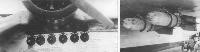
The power plant consisted of four BMW-VI engines located in two pairs in tandem. The selection of liquid-cooled linear motors significantly increased the weight of the aircraft, but Chetverikov knowingly decided to take the risk. The two engines of each installation shared a single radiator located in the lower part of the front-mounted one and were supported on a structure of rigid supports, facilitating access for service and maintenance. The fuel tanks were made of duralumin, being located in the centroplane.
The crew consisted of 7 people. The pilots were located in a closed cabin, with seats side by side. The navigator and gunners were located in positions similar to those of the TB-5. In the bow area, a watertight department was prepared to store cargo and equipment.
Defensive armament was generally similar to that of the bomber and consisted of eight Degtyaryov light machine guns for aircraft in four paired installations located in turrets. The MDR-3 could carry two 250 kg bombs hung on the rails, between the centerplane bracing supports.
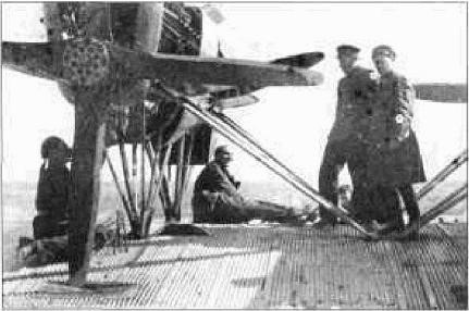
The construction of the model took place in the spring of 1931 and the prototype was found finished for the month of December. Unarmed it was sent to Sevastopol, where the first flight was made on January 14, 1932, with the pilot BL Buxgolts at the controls. Engineer A. Dnieprov and Chetverikov himself also participated in this flight.
About this flight Chetverikov wrote: – “Let’s go” – said Buxgolts and accelerated. We moved forward, the plane lifts its nose easily, begins to glide without splashing, increases its speed easily and smoothly takes off from the water. All good!
At an altitude of 600 meters we make the first turn, then a circle over the bay, planing and a gentle landing. “I have no markings,” said Buxgolts. As we headed into the Dnieprov bay he began to look to see if there was any water on the hull. – “Surely everything is excellent – said Dnieprov upon returning – Just hurry up guys, quickly to the shore or we will sink! There are leaks at the bottom and the apartments are taking on water pretty fast. If we take longer than necessary, we will sink in front of the public.”
This was expected. The hull took 10 months to build and was finished without checking its tightness.
The next flights were delayed due to the sealing work on the hull. Taking into account that the production base was very far away, these jobs were not easy at all.
Finally the boat was ready and the flights could continue. Three – four short flights were made to define the small defects and familiarize the pilot with the model. On one of these flights we made the landing outside the bay, with considerable waves, and we verified that the plane did not deceive us in relation to its seaworthy behavior. We can start with the test flights.
The next flight was intended to define the flight ceiling, the rate of climb and the maximum speed. After a good takeoff the plane began to gain altitude. Initially it was found that the rate of climb was lower than calculated. After an hour of flight the plane had only managed to rise to about 2000 meters.
During this flight, creaking noises were observed in the rear area of the flying boat. The tail began to vibrate and move from side to side. Continuing the flight was dangerous, so it was decided to return.
Later tests showed the appearance of important vibrations that started from the tail towards the nose. The cause of this phenomenon was attributed to the action of the propellers of the tandem drive installations. After replacing the propellers with ones from a Dornier Wal, the vibrations practically disappeared, but the total solution of the problem required a radical redesign of the tail area.
The tests were carried out until March 25 and during their execution a speed of 210 km/h was achieved and excellent seaworthy conditions were demonstrated. As a positive aspect, the excellent autonomy and the great range of the model were pointed out. As negative aspects, the poor rate of ascent and the low ceiling, which only reached 2,200 meters, were pointed out.
The studies carried out showed that the fundamental cause of the poor performance lay in the inefficient engine configuration selected and the poor aerodynamics of the model: poor design of the underwing stabilizers with circular fronts, absence of aerodynamic fairings for the supports and structures, poor design of the radiators, located on the wing in a way that diminished its effectiveness, a terrible solution for the location of the 250 kg bombs on the sides. To all this were added the finishing problems and a series of details that affected the lines of the fuselage.
As a consequence of these deficiencies, the result of the tests was assessed as negative. The MDR-3 failed to meet the requested specifications.
Taking into account the great need for aircraft of this type, the commissioners of defense and heavy industry approved the continuation of the development of the model, correcting the deficiencies that affected the aerodynamics. A short time later the plans and calculations of the MDR-3 were delivered to AN Túpolev in the KOSOS TsAGI to work on the solution to the indicated problems. Tupolev decided not to waste time on modifications to the flying boat and to design a new model. Based on the MDR-3, in 1933 the brigade led by II Pogosski designed the flying boat MDR-4 (ANT-27). The new flying boat retained only the hull lines of the previous model. The new configuration included a high cantilever wing, three engines and a monoplane tail with a single tail.
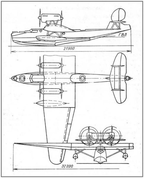
MDR-3
Engines: 4 × 500/680 hp BMW-VI
Wingspan: 32.2m
Wing area: 153.00 m²
Length: 21.9m
Height: 7.0m
Empty weight: 8928 kg
Maximum takeoff weight: 13973 kg
Wing loading: 91.5 kg/m²
Power Load: 5.1kg/hp
Fuel load: 3300 kg
Total load capacity: 5044 kg
Maximum speed at sea level: 210 km/h
Landing speed: 110km/h
Practical range: 1600 km
Autonomy: 9 hours
Practical ceiling: 2200 m
Take off time: 36s
Accommodation: 7
Armament: 8 Degtyaryov 7.62 mm machine guns
Bombload: two 250 kg
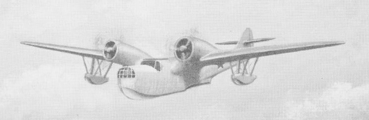
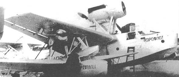
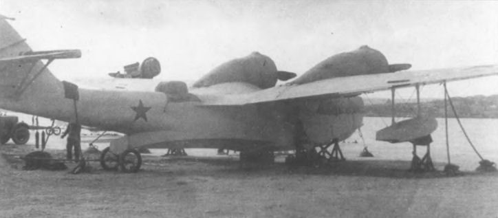
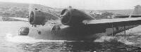
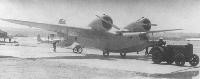
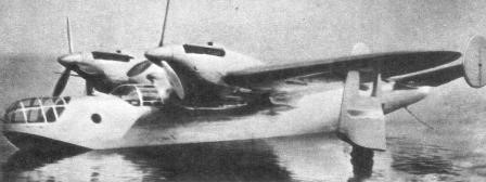
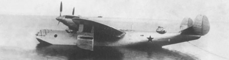
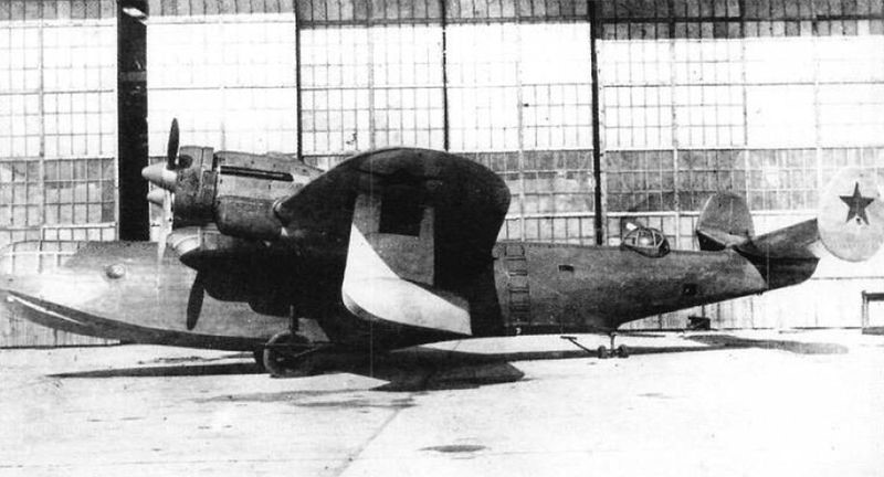
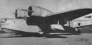
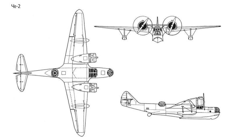
Shortly before the start of World War II, the USSR Naval Fleet received several types of flying boats, among which a model designed by a group of engineers under the general direction of IV Chetverikov stands out. This model, known as the MDR-6 after the acronym for Morskoi Dalni Razvietchik or Long -Range Naval Reconnaissance, distinguished itself by using a gull-wing configuration allowing the propellers to be moved away from the water without the need to increase the depth of the hull or resort to parasol wing schemes.
The MDR-6 or Che-2 (Четвериков МДР-6 (ЧЕ-2)) was designed from specifications issued in 1934 and reviewed by the mock-up approval commission on December 4, 1936.
It was produced in series as Che-2 between 1940 and 1941, 50 being built at Taganrog between 1939 and German invasion of Crimea in 1941. The short range and its designer’s attempt to obtain speeds similar to those of land-based bombers resulted in the appearance of a number of experimental models, which did not go into production due to the presence in the USSR of the Consolidated PBY Catalina, obtained under the Lend-Lease Act.
The MDR-6 was designed as an all-metal monoplane flying boat. The wing was shaped like a “gull” with a high set-up and cantilever configuration. Weight-compensating ailerons and hydraulically actuated flaps were installed on the trailing edge.
Construction was carried out by Factory No.45 in Sebastopol and the prototype was ready for its first flight in July 1937.
The M-25Ye engines used had been experimentally manufactured by Factory No.19, Perm, under the direction of Arkadi Dmitrievich Shvetsov, and used on a trial basis in the crashed ARK-3. The use of these experimental engines was considered as a temporary measure intended to speed up the development of the model tests.
The M-62 was considered more suitable as it featured similar shapes and the same mounting points as the Shvetsov M-25, while offering more take-off power with minimal weight gain. Improved performance, increased rate of climb, and fuel economy were expected with the M-62 engine.
The centroplane was inserted at an angle against the body of the flying boat, ending in the form of a fairing. At the other end of the midplane, the engines were installed high above the wing turning point, in order to move the propellers as far out of the water as possible. The wing consoles were trapezoidal in plan with elliptical ends. The dimensions of the wing changed with the development of the model. The first prototype featured fixed stabilization floats, maintaining this configuration in the production copies, but later experimental models introduced retraction systems seeking to improve performance.
The hull had a double groove and a pronounced keel. The first redient had a transverse shape and the second sharp. The entire cross section of the flying boat showed curved lines. The model’s nose was very short, necessitating the use of splash deflectors. After the first tests it became necessary to make some modifications to the reentrants and the bow area. Behind the second redient a rudder was installed. These changes were implemented at Factory No.45 in Sebastopol and resulted in increased stability in the water and decreased splashing during takeoff and landing operations.
The entire aircraft was covered with metal sheets with thicknesses between 0.8 and 2 mm, except for the ailerons, rudders, the rear part of the wings and, in some models, the keel.
The tail was of a conventional monoplane type with the planes set high on the keel. After the first flights, mounting brackets for the tailplanes with trimmers and weight compensators on the rudders were introduced. The rigid engine control system was replaced by cables.
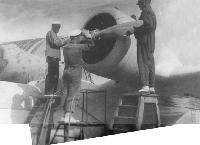
The fixing of the motors to the wing was carried out by means of supports installed directly on the wing structure, without using independent benches. The wing included in its structure 10 fuel tanks and two oil tanks, with capacities of 2,160 and 240 liters respectively. The M-25Ye engines with a nominal power of 710 hp at 5,400 m and a weight of 453 kg, moved variable-pitch VISh-6 propellers with a diameter of 2.8 meters.
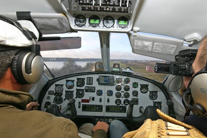
The crew of the MDR-6 was made up of four people: two pilots, a navigator and a gunner-radio operator, located in three segments of the hull separated by watertight walls. An RSRM radio station and an AFA-13 camera were located in the radio operator’s cabin. In the cockpit of the pilots an RSVS radio. The internal communication system included a SPU-3 intercom, pneumatic mail system, a light signal system with three lamps, and the RSVS radio station. For radio transmissions when the flying boat was on the water, a retractable mast was designed for the antenna.
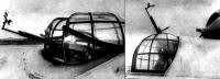
The armament was distributed in three firing points. In the nose was located a NU-DB-3 installation with a 7.62 mm ShKAS machine gun and a KPT-5 sight. The ammunition box with 1000 shots was located on the right side. At the bottom of the hull was a mat on which the shooter sat. In the upper part of the turret there was a slot to place the machine gun firing at an upward angle. When the machine gun was not installed this opening was sealed by three small armored shields.
The intermediate station featured an SU-DB-3 type turret with a 7.62mm ShKAS machine gun with 2000 rounds. Steps were installed on the hull floor to facilitate operation from this position. The operator of this weapon had a retractable seat. In the rotating ring of the turret the fixation of an oxygen system was envisaged.
The rear firing point was shaped like a hatch and was similar to the one used in the lower area of the rear fuselage on the Ilyushin DB-3 bomber. It was equipped with a 7.62mm ShKAS machine gun. The ammunition box with 1000 shots was placed on a designed surface on the right side. During the transfer, the machine gun was kept in a vertical position fixed to the right side of the flying boat. A safety belt for the shooter was located on the left side lining.
The maximum bomb capacity of the MDR-6 was 1,200 kg. The compositions varied and could be one of the following:
12 FAB-100 or FAB-50;
4 FAB-250 or BRAB-220;
2 FAB-200.
The FAB-250 and FAB-500 heavy bombs were attached to DER-19 external mounts located in pairs under the wings. The fixation of these bombs was carried out by means of a BL-3 rope system located on the surfaces of the plane. The FAB-100 bombs were located in horizontal cassettes fixed to DER-31M supports. These cassettes were located under the wings inside the locations of the DER-19 mounts and the attachment of the bombs to them was done manually. Two DER-32 brackets for flares were also installed. The launch systems were linked to the supports by a cable system that included emergency wiring. The bombing system used an OPB-2 targeting system.
During the development of the tests, the possibility of using the UJAB-500 universal chemical weapons container built by Factory No.145 of the NKAP was evaluated in the MDR-6. With dimensions similar to those of a FAB-500 bomb this container could be located under the wing.
The first MDR-6-2M-25Ye was built as a long-range naval reconnaissance flying boat and light bomber and was generally a military development of the ARK-3/2 polar scout.
The second stage of state tests of the experimental prototype MDR-6 took place between July 2 and 22, 1939 in Sevastopol ( in the waters of Gollandia Bay and in Lake Donuzlav).
The test brigade was composed of:
Chief Engineer: Military Engineer 2nd Rank NI Chernyshiov;
Assistant Chief Engineer: Military Engineer 3rd Rank Kolchinsky
Lead Pilot: Major Slobodchikov;
Chief of Armament Engineers: Major Tyutlyayev;
Assistant to the Chief of Armament Engineers: Military Technician 1st Rank Borobiov;
Chief Engineer at VMG: Third Rank Military Engineer Bielkind;
Navigator: Senior Lieutenant Oljovikov;
Second Pilot: Senior Lieutenant Yefimienko;
Shipboard Technician: Military Technician 1st Rank Salomatov;
The program of the tests was approved by the head of the AU RKVMF division commander Zhavoronkov and the military commissar of the AU RKVMF brigade commissar Alexeyev. The test results report was signed by the head of the VVS of the Black Sea Fleet Brigade Commander Rusakov and the military commissar of the LII ARKVMF Battalion Commissar Mochalov.
The tests comprised 14 runs and 39 flights. Of these last 13 were made in a circle, 10 looking for behaviour at height and 16 normal flights, totalling 34 hours in the air. On land they accumulated another 5 hours. Of the total flights, 30 were carried out with payloads in exploration and bomber variants. Operations were carried out with wind speeds of up to 8 meters per second and waves of up to 0.5 meters. The maximum recorded overloads reached the value of 1.78 g.
During the flights a maximum speed of 405 km/h was reached with a ceiling of 5835 meters. No vibrations were seen in any of the tests. Bomb load turn tests were performed on cassettes of 12 FAB-100s for a flight weight of 5,900 kg.
According to the resulting documents, the tests of the MDR-6-2M-25Ye in relation to overloads, seaworthiness, take-off and landing characteristics and flutter resistance were considered positive.
The report recorded:
“The plane was towed by a boat to the exit of the cove and the engines were started there. Thanks to the optimal location of the engines and the presence of an effective rudder, the MDR-6-2M-25Ye is very maneuverable in the waves. The race to the start can be done with a single motor at values between 500 and 1200 revolutions per minute.
The aircraft safely maintains the course, does not show any tendency to drift during takeoff and navigates stable on the edge. After takeoff, the machine behaves normally and when it reaches 150 km/h speed, it smoothly searches for the angle of climb. The loads on the stick are decreased by the elevator trimmers.
In horizontal flight, the plane presents a good balance in all speeds, positions and weights, maintaining centering between 28% and 34% of the length. The longitudinal and transverse stabilities are good if the tendency to bite on the wing is appreciated. In case of problems with the engines, it is easily passed to the glide regime. Upon failure of an engine, the airplane at normal flying weight can continue to fly after removing the load from the rudder trimmer and giving full throttle to the operating engine.
The aircraft responds promptly to the rudder with a normal stick load in all flight regimes and with loads up to 7,000 kg can be easily balanced using the trimmers. The effectiveness of the rudders in takeoff, flight and landing can be considered sufficient.
Recovery after a turn is easy with the rudder, without the need to vary the work rite of the motors or use the trimmers. The optimum turn is made with a bank of 60 degrees at 210 km/h. The turn is stable, without tendencies to dive or jump.
The entry and exit of the spirals is done with the help of the rudder without the need for trimmers and motors. In the spiral the plane is stable. The optimal spiral is obtained at 180 km/h with an angle of 45 degrees.
Flutter was not observed in any of the flight regimes.
Switching from any flight regime to glide is easily done with the rudder. The plane during the glide is stable in the longitudinal and transverse axis. Optimum glide speed with flaps extended is 150 – 160 km/h on instruments (depending on load).
Landing depends on the position of the aerodynamic brakes. With them extended the landing is rougher, without them the glide angle is lower and the plane descends smoothly (as with the MBR-2). Landing takes place at speeds of 110 – 115 km/h and the run lasts about 18 – 20 seconds, depending on the load. In this operation no trends of deviation are appreciated.
The aircraft normally lands in crosswinds of 6 – 8 m/s and at angles of 65 – 70º to the wind direction. After landing the hydrocanoe can sail to the entrance of the bay or turn off the engines and wait to be towed from the bow hooks by a speedboat.
The aircraft is comfortable for pilot training due to its side-by-side seating arrangement, duplication of controls and instruments, and visibility from either seat. The piloting technique is simple and accessible to a pilot of medium qualification.”
Despite these evaluations, some negative aspects were also pointed out, among which the following stood out:
Difficult working conditions of the propellers in airplane overload conditions, which led to their replacement every 40-45 flight hours;
Failure of the oil cooling system;
The need to modify the fuel supply system in a way that would allow the fuel tanks to be replaced without having to disassemble the wing;
The fuel capacity, acceptable for bombing missions, was insufficient for reconnaissance tasks;
Need to improve engine hoods;
Poor visibility from the navigator’s cabin. The small skylights on the railings did not guarantee the necessary visibility (the visual sector only admitted 60 – 70º);
The cockpit and forward position received water during runs and take off, which increased depending on the strength of the wind;
The anchor was located under the pilot’s seat on the right, so the navigator had difficult access to it
The navigator’s seat was in a comfortable position but needed modifications because in order to observe through the turret windows it was necessary to stand up;
The SPU-3 intercom system performed poorly during testing and the pneumatic mail system proved to be ineffective. The light signals, on the other hand, worked very well;
The AFA-13 photographic apparatus was located with all the rest of the equipment in the shooter-radio operator’s cabin, which made its use difficult;
In the navigator’s cabin, the lack of equipment necessary for his work was felt: visual orientation when taking the course could only be done by looking through the turret screens, the liaison with the pilot in these operations was only in writing, location measurements had to be made using the OPB-2 collimator, radio equipment for navigation was lacking; orientation by stars through the upper hatch could hardly be carried out by the force of the wind in the absence of a transparent cover.
One of the collateral tasks of the military tests was the study of the conservation conditions of the flying boat. The MDR-6 could be kept in hangars and in the open air. Exit from the hangar and transfer to the water was carried out with the help of a JTZ (ХТЗ) tractor. In case of lacking the tractor this operation could be done by eight people.
The entry and exit of the water was carried out by three people with the help of a pair of divers. The time of putting in the water counting on the removal of the transfer wheels took 3 – 5 minutes. This process required a JTZ tractor, a PPK-35 crane, a tail lift jack, a Yaroslaviets boat, a BZ-35 (БЗ-35) tanker, an APV-4N (АПВ-4Н) engine heater, a thermos of water – oil VMT-35 (ВМТ-35). For winter operations, a GAZ-AA (ГАЗ-АА) starting system and a ChTZ (ЧТЗ) tractor for ski operations were added. Extraction from the water took 5-7 minutes.
Refueling time from the BZ-35 tanker with two hoses took about 10 minutes and oil about 30 minutes (due to the narrowness of the oil intake).
Access to the engines was highlighted as a positive, but it was pointed out that there were few hatches for the maintenance of the systems and aggregates and many maintenance actions required the disassembly of the hoods, which considerably increased the time of interventions;
In general, the assessment of these conditions showed that the MDR-6 did not need special conditions for its operation and could operate from the same bases used for the MBR-2 flying boats.
In relation to the armament system, it was found that it was difficult to guarantee hitting the targets due to the lack of windows in the bow, under the turret. The target was lost under the plane and the launch of the bombs could be sensed, using the ESBR-3 and AS-5 systems for their release.
The DER-19 supports proved to be very vulnerable to weather conditions. At temperatures below 20-25 degrees, the number of failures tended to increase and they were quite sensitive to the action of saltpeter, which required constant maintenance.
The forward navigator’s turret easily received seawater during overwater operations, necessitating careful cleaning of this area after each flight to prevent corrosion of the turret and armament. The hatch type station located in the lower part of the tail also received a lot of water, which affected the operation of the machine gun.
During the weapons tests from the UN turret, it was verified that the shot was effective in any position and at any height, differing only in the speed of the maneuver. The installation guaranteed all the permissible angles of the shot. Visibility was allowed by the armor screen at all angles of turret operation. It was noted that the turret lacked limiters so there was the possibility of firing the engines during combat. The weapon’s feeding system did not generate any signal. The link between the navigator’s cabin and the turret was also considered without difficulties.
The location of the machine gun on the right rail and vertical position when not in use was valued as very positive. In that location it did not affect the work of the navigator or the pilots.
By directing the dorsal “SET” turret (from the acronym Samoliotnaya Elektrofitsirovannaya Turel or Electrified Aviation Turret) backwards or forwards at angles of 30 – 40º the sides of the hull limited the aiming angle. The oxygen system could be fixed to the mobile part of the ring in the gunner’s turret, but its short hose did not allow moving from the dorsal to the tail turret without loading the ball, which made the shot more complex. The instrument board had a correct position and even serving the machine gun you could turn your head and see the indicators.
The feeding system of the machine gun in the rear turret type “LU” did not present an acceptable termination and the bushings collided when falling with the control cables of the maritime rudder. Water accumulated in the hatch that bathed the gunner and the armament during opening. The cockpit was tight and uncomfortable to shoot lying down. The mounting base of the machine gun was not strong enough, although its assembly and disassembly were easy.
The variants of bomb loads were tested on land and in the water. In the latter case, a special raft designed by Factory No.48 was used, which in practice proved to be ineffective. Above the water, the FAB-500 pumps were raised by means of a pulley mechanism operated by one person. The ground operation was carried out by three men from a wheelbarrow. The average installation time for four FAB-250 bombs on the ground was 40 – 50 minutes. The installation of 12 FAB-100 bombs was carried out by 5 people in 45 – 50 minutes, including the installation of the triggers.
The tests showed that during takeoff and landing operations, the pumps and supports suffered constant splashes of water, especially the first three located closer to the sides. The DER-19 supports, operated from the ESBR-3 and AS-5, worked without problems. The use of the OPB-2 aiming system was comfortable. DER-32 media failed the low temperature test.
When placing the pumps in the cassettes, it was possible to verify that due to lack of rigidity, the pumps located near the ends and the center began to vibrate during takeoff and landing operations. The DER-31 mounts worked without a problem.
The actual capacity of large caliber bombs was 1000 kg in configuration of 4 FAB-250 or two FAB-500. It was considered that the requirement of the evaluation commission of the model was not met, which requested a maximum load of 1500 kg (six FAB-250).
The pulley system for installing the heavy gauge pumps was approved for installation on production examples after some minor modifications. It was decided to develop a new raft in order to be able to install pumps in the water in any weather conditions.
On July 20, 1939, a test combat of the MDR-6-2M-25Ye was held with a group of Polikarpov I-16 fighters, which lasted one hour and took place at altitudes of 1,500 – 2,000 meters. All the planes were equipped with SLP photo-machine guns in order to define the defensive capacity of the flying boat and the maneuverability of the armament.
The MDR-6-2M-25Ye would fly along the Donuzlav Lake – Kamenolomnya airfield route at an altitude of 3,000 meters. The fighters should take off from their airfield when the MDR-6 descended to 1000 meters. Fighter attacks would be made from heights of 3,000-3,500 meters.
The crew of the MDR-6 consisted of senior tester pilot Slovodchikov, navigator and bow gunner senior lieutenant Olkhvikov, second-rank engineer Chernishov as second pilot, senior weapons engineer Tyutlyayev as dorsal gunner in the “SET” turret. and Military Technician 1st Rank Borobiov as Gunner of the “LU” Tail Station.
The crew of the I-16 fighters consisted of Regimental Commander Major Pavlov (leader) and Squadron Commander Captain Shubikov and Senior Lieutenant Yashkin as points.
During the fighter attacks the flying boat managed to maintain a speed of 250 – 275 km/h. The results of the tests showed that the MDR-6 was vulnerable to attack by the fighters and that the success of the reconnaissance mission would be based on avoiding combat with the enemy fighters, arriving unexpectedly at the objectives and remaining there for the least amount of time. possible time.
It was determined that the defense of the rear hemisphere was insufficient, especially in the tail area, where “dead zones” were formed that were not covered by machine gun fire. The absence of side hatches considerably reduced the effectiveness of the lower “LU” station. It was shown that in practice a single crew member was unable to defend the “SET” and “LU” stations at the same time. At high altitudes, changing from one position to another was difficult and quickly tiring. On the other hand, if the shooter-radista was wounded, the entire rear hemisphere was left unprotected.
In the report of the results of the combat tests it was considered, despite the deficiencies indicated, that the defensive capacity of the MDR-6 was acceptable for this type of aircraft. The MDR-6 with M-25Ye engines managed to pass combat tests.
As a result of state and combat tests the MDR-6-2M-25Ye was approved for serial production at Factory No.45 and entered service with the RKVMF.
To create the base model for production it was proposed to Chetverikov to prepare the model with a set of modifications and resubmit it for state tests. This upgraded model was to feature two Shvietsov M-62 engines with in-flight variable pitch propellers, ability to mount wheels or skis, upgraded bomb cassette system, modifications to defensive system and chemical weaponry, revised oil cooling system, protection of fuel tanks against impacts and increase in capacity to 2200 kg.
It was projected to locate in one of the series copies to be produced in 1940 some machine gun installations in the motor gondolas, in order to increase the defensive capacity.
The second prototype with Shvietsov M-63 engines was selected as the base model for the series and received the factory designation “H”. This specimen had a slightly larger wingspan and the stabilization floats were braced by tension straps. The tailplanes featured V-shaped bracing supports.
This prototype presented the possibility of installing wheels without the need to lift it, which could be replaced in winter by skis. The takeoff weight reached 5,600 kg and 6,450 kg in the supercharged version.
This example was successfully tested between September 21 and October 4, 1940 by the test pilot Shevnin, showing a speed of 338 km/h at sea level and a calculated technical range of 2,650 km. Performance was initially considered satisfactory, but claims were soon made to bring it closer to that of the Ilyushin DB-3 bomber, forcing Chetverikov to work through various development versions.
Factory No.31 in Taganrog was initially selected to carry out mass production of the model, which began work in September 1940. At the beginning of 1941 Chetverikov was appointed chief builder of Factory No.30, located in Savielov, with the task of producing 100 examples of the model.
Production of the Che-2 closed in 1941. Different sources assert that a total of between 20 and 50 copies of the Che-2 (name of the MDR-6 from 1941 in honor of its designer) were produced, but more recent studies establish that production in only 17 copies, of which 13 were finished in Taganrog and only 4 in Factory No.30.
Most production examples were delivered in a version sometimes referenced as the MDR-6A, with 1,100 hp Shvietsov M-63 engines, although some were completed with M-62s.
The Che-2 featured a composition quite similar to the MDR-6-2M-25Ye in relation to the location of its firing points. The defensive armament was generally made up of three 7.62 mm machine guns, but in some units it was replaced by one 12.7 mm machine gun and two 7.62 machine guns. The maximum bomb capacity reached 1200 kg, but generally the Che-2 flew with a load of only 400 kg. The last examples produced featured a modified bow turret and an MV-5 turret in the dorsal position, as well as the use of unguided rockets in underwing installations.
Despite its large dimensions, the airframe was quite light. The empty weight did not exceed 4100 kg and the flight weight 6700 kg. In overloaded version the aircraft reached 7200 kg. Its streamlined shapes allowed the MDR-6 to display good flight characteristics and excellent seaworthiness. The maximum speed reached 360 km/h and the ceiling 9000 meters.
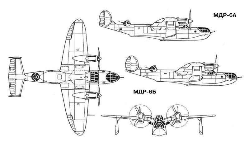
Chetverikov set out to raise the flight characteristics of the MDR-6 with the aim of bringing them as close as possible to those of the Ilyushin DB-3 serial bomber and along the way he set out to develop a set of versions that were known as “A” and later “B” in variants 1 to 5.
In some literature the MDR-6B versions are known under the name Che-6. Both versions differed significantly from the production prototype, also known as the “H”. Visually, the redesign of the bow and the introduction of a bi-derived tail with a notable positive dihedral stood out. Another noteworthy aspect was the substitution of the radial motors for other linear V-shaped ones with water cooling.
Version “A” appeared in 1940 and was characterized by the introduction of inline motors M-105 of 1050 hp of power and a reduction in wingspan to improve speed. In some sources this model has been called the MDR-6A/2 to differentiate it from the standard MDR-6A (Che-2). The underwing floats were modified, presenting a characteristic shape that allowed them to retract until they were located between the wing spars.
The bow turret and cockpit glazing were modified, obtaining a much more streamlined shape and increased glazing. The rear turret was moved to the rear area and the tail was modified with independent sharp dihedral planes with drifts and stabilizer tip terminal rudders.
The hull kept the same thickness of 1.9 meters and the construction was basically the same with a semi-monocoque structure. The internal skeleton was built on the basis of pressed and shaped beams. The bow featured a new design in which the rotating turret had been removed.
The projection of the model “A” began in the fall of 1939. The specimen was produced in 1940 and between that year and the following year it passed the factory tests, which were carried out by the pilot D. Slavodchikov, but unfortunately it was destroyed in an accident that occurred near Uglich, during the transfer flight to the construction site. of state tests.
The MDR-6B or B1 was a modification of the original MDR-6 and like the “A” version used a 1050 hp M-105 linear water-cooled powerplant and shortened wing consoles for higher speed. The stabilization floats in this version were enlarged so that they could not be inserted completely inside the wing plane.
The wing featured all-metal construction with two spars made from 60x60x6 mm steel profiles. The coating up to the second spar was 2 mm thick in the center plane and at the base of the consoles and 0.8 mm thick towards the wingtip. The posterior area presented tissue coverage.
The M-105 engines had less frontal area than the M-63, even despite the need to install radiators for the water, which were located under the midplane, behind the second spar.
The flying boat featured very clean lines, making it one of the most visually pleasing models built in the USSR. The speed reached 454 km/h at an altitude of 6000 meters. The armament remained similar to that of the initial model and consisted of three ShKAS machine guns and a load of 1000 kg of bombs.
The MDR-6B1 saw the light of day in the spring of 1941 and passed factory tests without difficulty. On October 26 of that year, the flying boat was flown to the site where the acceptance or state tests were to be carried out. The B-1 arrived without problems but the tests could not be concluded due to the presence of problems with the power plant. Problems were also detected with the retraction system for the stabilizing floats, which were not fully inserted into the wing due to a defect in the design of the arms of the collection mechanism. The new engines brought the propellers closer to the water as a result. In this case, not only the splashes, but even the waves, reached the rotating blades.
The model was considered to be prospective, but it called for modifications in a series of aspects and improvements to the power plant. It was also requested to take measures to increase the scope.
The MDR-6B2 was a development of the MDR-6B1 and generally repeated its construction and dimensions. This model appeared in 1943 with the same M-105 engine as the previous model but incorporated radiators inserted into the wing leading edge using lattice-type grilles in an implementation similar to that used on the Tupolev SB bomber. In this model the floats were presented with increased volume and when they retracted they were not completely inserted into the wing.
The hull had the same dimensions, but the increased weight had raised the waterline. The seaworthiness was slightly affected and despite the installation of splash deflectors, taking off in waves was quite difficult.
During tests this model showed similar performance to the MDR-6A but the range remained insufficient.
The MDR-6B3 had the same dimensions and wing construction as the previous B-series models. Its construction was developed in 1943 in parallel with the B2 and the only noticeable difference at first glance was the use of an M-105PF 1150 engine. hp (variant made from 1942; changes introduced allowed a significant increase in power output at the expense of performance at higher altitudes) on newly designed power pods and slightly modified stabilization floats. Another difference was the installation of a more powerful defensive armament: two UB machine guns were located in the tail area and the crew was increased to 5 people.
The maximum weight of this variant grew, reaching 7,200 kg in normal version and 8,200 kg in supercharged configuration. Internal fuel capacity was 1,100 kg.
Despite impressive performance improvements over the standard Che-2, this model was not liked by the Soviet Navy as a result of its inadequate hydrodynamic performance in heavy seas.
To achieve the range of 3000 km requested in the specifications, the MDR-6B4 version was created, which saw the light in 1944 and for the first time introduced important modifications aimed at improving the seaworthy characteristics and preventing the propellers from coming into contact with seawater.
The hull of the flying boat was thickened, reaching 2.2 meters instead of 1.9 meters in the initial versions and the overall height was increased by 0.4 meters with elevation of the tail area and empennage. The rear tooth was displaced backwards. As a distinctive aspect, the empennage surface was increased by adding a third keel in the central position.
The stabilization floats became fixed, located on braced supports. It became necessary to abandon its retraction because when increasing the height of the flying boat it was necessary to lengthen the supports of the floats and they could no longer be housed in their old position.
As powerplant this model kept the 1150 hp M-105PF with radiators inserted in the leading edge of the wing. Fuel capacity was increased to 2,150 kg. The total weight of the new model was increased to 10 tons.
The crew of the B4 was five people. Defensive points were improved, increasing coverage angles. Defensive armament included three UB machine guns, maintaining the same 1,000 kg bomb load of earlier models.
The tests of the model (factory and state) were carried out between July 4 and October 18 at the test base of Factory No.458. IM Sujomlin was selected as test pilot and flights were made with a total duration of 8 hours and 36 minutes. On October 30, 1945, the aircraft made a flight along the Taganrog – Stalingrad – Astrakhan – Baku route as part of the joint test program.
Deliveries of Consolidated PBY Catalina flying boats under the Lend-Lease law greatly harmed the possibility of production of the MDR-6B-4.
The MDR-6B5 was the most advanced model of the experimental series and its production was not approved due to the end of the war and the concept that large flying boats were no longer necessary.
The MDR-6B5 was the last experimental model of this flying boat and was a development of the B4 with a new 1700 hp VK-107 engine. The radiators featured lattices at the outlets and were located under the wing, between the spars. The propellers were metallic with variable pitch and three blades.
The hull was similar to that of the MDR-6B4, but included a 0.5 meter lengthening of the nose obtained by moving the cockpit forward with respect to the wing leading edge. The midplane was enlarged and the consoles remained similar to those of the B4. The tail unit increased its area, but the central empennage disappeared.
Armament was enhanced with the installation of three 20mm B-20 cannons. One cannon was located in a fixed installation in the nose and held 200 shells. Two other guns were installed in the “SEB” turret (from Samoliotnaya Elektrofitsirovannaya Bashnya or Aviation Electrified Turret) with 300 rounds. Bomb capacity remained similar to previous models, being able to include four FAB-250 monsters or two FAB-500s.
The weight of the armament reached 125 kg, air navigation instrumentation – 69 kg, electrical and communications equipment – 172 kg, other equipment and materials – 542 kg. The constructive weight of the aircraft was 235 kg, the engines weighed 3067 kg. The empty weight of the B5 was 5610 kg, almost the takeoff weight of the Che-2 and its flight weight exceeded 10 tons.
The prototype of this version was completed by the summer of 1945 and successfully passed factory tests. During the tests, the excellent maneuverability of the model and its good seaworthiness were highlighted. With the approaching end of the war the plane was not handed over to state tests.
The first MDR-6 examples (by that time Che-2) were framed in units of the VVS of the Baltic Fleet at the end of 1940. From July 1941 two squadrons with these aircraft operated from Tallinn, carrying out reconnaissance tasks in the central and southern regions of the Baltic Sea, sometimes reaching the German coast.
In August 1941 the Che-2s participated in securing the bombing raids on Berlin carried out by DB-3F bombers from Saariema Island, being used as floating signallers on the water.
In September 1941 the Baltic specimens were transferred to the Northern Fleet where they were used primarily for distant reconnaissance. The Che-2s carried out reconnaissance on the icy waters looking for enemy ships. Most of these specimens had been lost by the end of 1941, but one specimen survived until the end of the war.
In the Black Sea the Che-2 operated from the summer of 1942. From Gelendzhik and then from Poti, conducting reconnaissance on German supply routes. In November-December these planes participated as cover for the naval group led by the cruiser “Voroshilov”. From 1943 the Che-2s were used mainly in the search for submarines. On August 4 of that year a Che-2 located a German submarine near Sukhumi, hitting it with an unguided rocket. The submarine was later sunk using depth charges. Later the Che-2 carried out some other attacks of this type in the black sea the model was used until the end of the war.
In the Pacific Ocean the model was used from 1941. Some copies were used in operations against Japan in August 1945.
The last examples of the Che-2 were withdrawn from active service in 1946.
MDR-6-2M-25Ye
Powerplant: Two 710 hp M-25Ye experimental radial engines
Wingspan: 22.00m
Wing area: 58.90 m²
Length: 15.80m
Height: 3.99m
Empty weight. 4087kg
Normal takeoff weight: 6450 kg
Maximum takeoff weight: 7000 kg
Top speed: 338km/h
Cruising speed: 286km/h
Practical range: 2650 km
Climb speed: 286m/min
Practical ceiling: 8500 m
Accommodation: 4 crew members (two pilots, navigator and gunner-radio op)
Armament: Three ShKAS machine guns
Bombload: 1000 kg
Che-2 / MDR-6A
Powerplant: Two 1,110 hp Shvietsov M-63 experimental radial engines
Wingspan: 21.00m
Wing area: 59.40 m²
Length: 15.73m
Height: 4.30m
Empty weight. 4100kg
Normal takeoff weight: 6700 kg
Maximum takeoff weight: 7200 kg
Maximum speed at 4000 meters: 360 km/h
Cruising speed: 309km/h
Practical range: 2650 km
Ascent speed: 35m/min
Climb to 5000 m: 12 minutes
Practical ceiling: 9000 m
Accommodation: 4-5 crew (two pilots, navigator, gunner-radio op and tail gunner)
Armament: One UB machine gun and two ShKAS
Bombload: 1000 kg
USSR
A 1928 graduate of Leningrad Institute of Transport Engineering, I. V. Chetverikov worked briefly with D. P. Grigorovich before joining the Tsentralnoe Konstruktorskoe Byuro (Central Design Bureau; TsKB). From 1931 -1933 was in charge of seaplane development section; responsible for designing MDR-3 reconnaissance flying-boat, OSGA-101 light amphibian, and related SPL submarine-borne small floatplane. His ARK-3 flying-boat was a failure, but the three-seat MDR-6 (or Che-2) of 1937 was produced for Soviet Naval Aviation, 50 being built at Taganrog between 1939 and German invasion of Crimea in 1941. Development, but no further production, of MDR- 6 continued during Second World War; after completion in 1947 of three prototypes of the eight-passenger TA-1 flying-boat, this bureau was closed down in 1948 and Chetverikov became a lecturer.
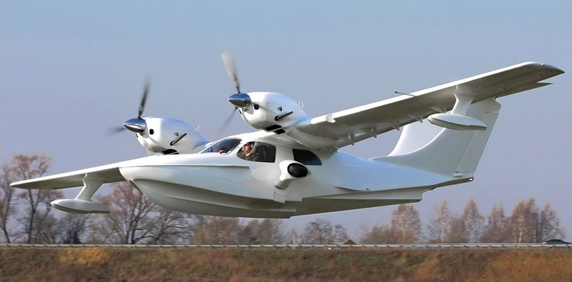
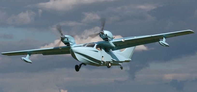
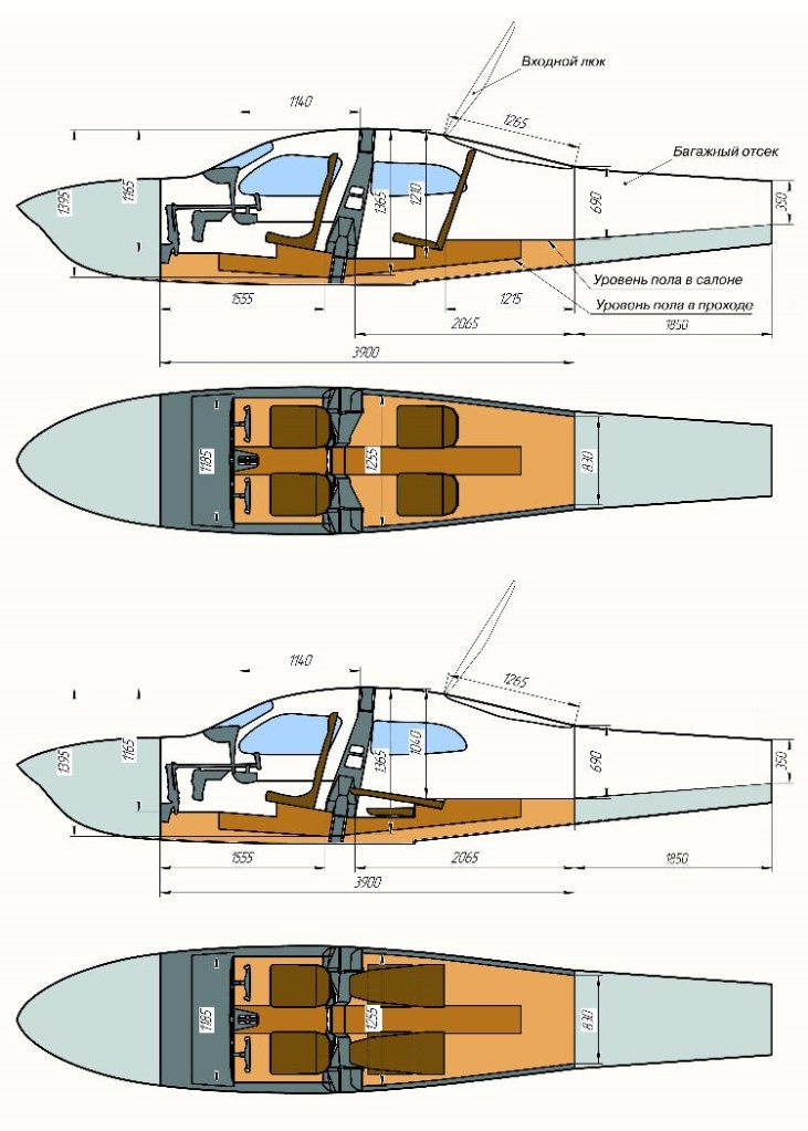
Several companies and groups have developed a series of designs which began at an offshoot of the Trod Kuznetsov aircraft engine plant in Samara. Beginning with the L-3, they differ in size and engine type but all are twin engine amphibians with a characteristic V tail. The L-4 is a direct development of the L-6M, promoted by AeroVolga. Its design began in August 2004.
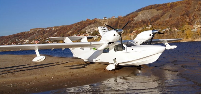
All L-4 variants have the same layout and all are largely built of composite materials. They are high-wing monoplanes with twin engines mounted close to the fuselage, on top of the wing. The wings have straight taper on both edges and almost square tips. The L-4 has a pair of flaps on each wing. Its hull has two steps and there are small winglets at waterlevel just aft of the trailing edge. The cabin extends from below the leading edge rearwards to the winglets. Fixed floats under the wings stabilize the L-4 on water; it is operable with waves to 400 mm (15 in) high.
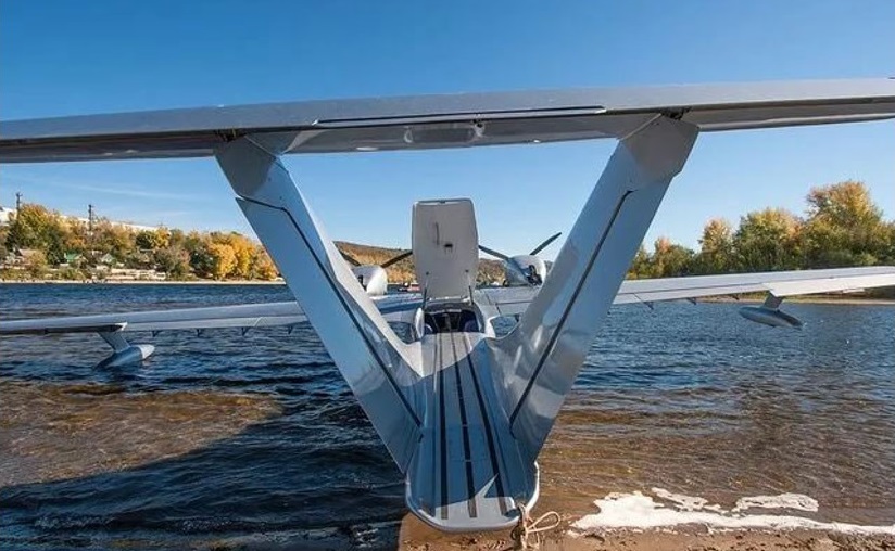
The most unusual feature of the L-4 is the empennage arrangement: it has twin fins, mounted on the fuselage and extended forward with long, curved dorsal fillets, separated at the base by the full fuselage width and leaning slightly outwards. The fins carry conventional rudders and the single tailplane is mounted upon the fin tips, extending well beyond them. Tailplane and single piece elevator together are trapezoidal; there is a trim tab at the centre of the elevator. The reason for the design is that the spine serves as a walkway to access the plane from behind, when moored at shore.
The L-4 has a conventional undercarriage for land use, all three wheels and the water rudder being retractable.
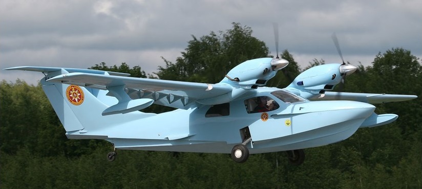
The first flight of the L-4 was in June 2005. The more powerful L-44 flew in 2009.
By mid-2008 sales, probably including L-6s from AeroVolga, had reached 14.
Chaika L-44 (English: Seagull).
Powerplant: 2 × Rotax 914, 84.5 kW (113.3 hp)
Propellers: 3-bladed Airmaster AR332
Wingspan: 13.50 m (44 ft 3 in)
Wing area: 22.45 m2 (241.6 sq ft)
Length: 8.50 m (27 ft 11 in)
Height: 2.52 m (8 ft 3 in) excluding propellers
Empty weight: 830 kg (1,830 lb)
Max takeoff weight: 1,460 kg (3,219 lb)
Fuel capacity: 230 kg (507 lb)
Maximum speed: 220 km/h (137 mph; 119 kn)
Cruise speed: 180 km/h (112 mph; 97 kn)
Never exceed speed: 250 km/h (155 mph; 135 kn)
Range: 1,598 km (993 mi; 863 nmi)
Service ceiling: 4,000 m (13,000 ft) service
Power/mass: 8.64 kg/kW (14.20 lb/hp)
Take-off run: 250 m (820 ft)
Crew: 1
Capacity: 3 passengers
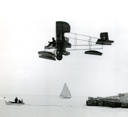
The Caudron pusher seaplane entered in the 1912 Monaco seaplane meeting featured three, big, flat-bottomed Fabre floats fitted in front of the wheels and one under the tail, a 60 hp six-cylinder Anzani engine. The pilot sat on a forward outrigger. In France it was referred to as a true “aero-amphibian” by virtue of its combined wheel-and-float undercarriage, because it could take off from and land on both land and water.

Span: 34’9″
Wing area: 35 sq.m
Length: 23’9″
Weight: 380 kg
Speed: 52 mph
