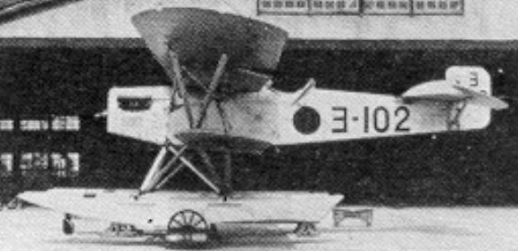
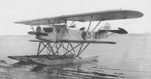
Built between 1927 and 1929, this two-seat twin-float sesquiplane was powered by a 224kW Hispano-Suiza engine and could attain a maximum speed of 166km/h. It was intended for shipboard reconnaissance and served with the Japanese navy as the Type 15 Reconnaissance Floatplane (Nakajima E2N1 and E2N2).
A total of 80 was built, many being relegated to training or sold to civil users during the 1930s.
Two machines were bought at the outset for civil fishery patrol duties. Converted by Itoh as the Itoh Emi 53, the Navy Type 15 conversions were completed in 1938, intended for use in fishery spotting.
E2N1 Engine: 1 x Hispano-Suiza, 224kW Max. speed: 166 km/h / 103 mph Crew: 2
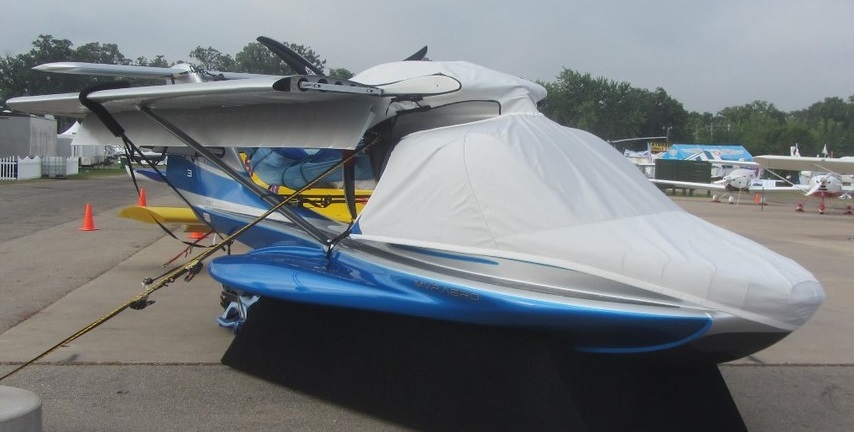
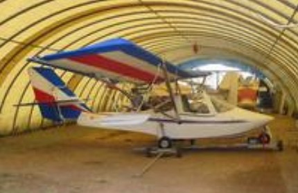
Designed by Mike Van Staagen, the MVP Model 3 is a prototype American “triphibian” light-sport aircraft, displayed in mockup form in 2014. The aircraft is under development by MVP.Aero Inc. of Delaware.
The MVP Model 3 is designed to operate on land, water, snow and ice. The floor panels can be rearranged to accommodate fishing or camping. The design will be marketed in several versions, including the E-AB, E-LSA, and S-LSA. The aircraft is a two-seats in side-by-side configuration with a pusher propeller and folding wings, which are constructed with carbon-fiber composite spars and covered with fabric. The balance of the airframe is constructed from a combination of carbon fiber and fiberglass. Electric thrusters help the aircraft manoeuvre in the water.
The design allows the canopy to be raised on a four bar system to sit above the engine cowling. This leaves the cockpit area open for fishing from and can also allow mounting of a tent for camping, with the floor panels inserted. With the canopy fully open the engine can still be run for water maneuvering.
The unit cost was US $169,000 as an Experimental and $189,000 as S-LSA.
Variants: Model 3 E-AB Model 3 E-LSA Model 3 S-LSA
MVP Model 3 Engine: 1 × Rotax 914, 115 hp (86 kW) Wingspan: 36 ft 0 in (10.97 m) Length: 23 ft 9 in (7.24 m) Length wings folded: 8.1 m (26 ft 7 in) Width: 8 ft 0 in (2.44 m) wings folded Fuel capacity: 26 US gal (22 imp gal; 98 l) Cruise speed: 104 kn (120 mph, 193 km/h) at sea level Stall speed: 41 kn (47 mph, 76 km/h) with full flaps Rate of climb: 1,000 ft/min (5.1 m/s) at sea level Wing loading: 11 lb/sq ft (54 kg/sq.m) Crew: one Capacity: one passenger
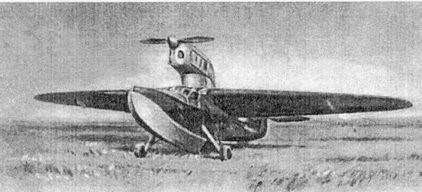
The SAM-11 training amphibian was developed in parallel with the Moscaliov SAM-10 and was designed with the same powerplant, the Bessonov MM-1 inverted linear engine. Its origins are based on a Naval Fleet Aviation (AVMF) request made to Moscaliev, which was originally scrapped due to the absence in Voronezh of a surface on which to test.
The Moscaliev SAM-11 Bekas (Russian: Москалёв САМ-11 «Бекас») amphibian was designed for training and liaison.
The designation SAM-11 in the OKB-31 and the name “Bekas” (Woodcock or Chocha), follows a custom of those years of assigning names of seabirds to flying boats.
Specialists from the naval department of TsAGI participated in the general configuration and a scale model was tested.
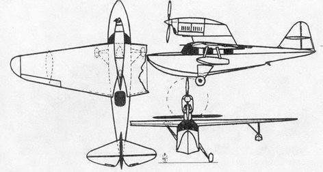
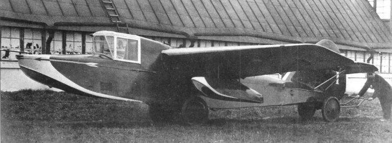
The SAM-11 amphibian was designed as a two-seat monoplane with a high cantilever wing with fixed stabilization floats on the wing consoles. All construction was made of wood. To speed up work, the wing and tail unit were taken from the Moscaliev SAM-10 with minor modifications such as openings to collect the wheels.
The double hull was built in wood with a waterproof resin coating and fabric. The use of wood and the need for reinforcement made the SAM-11 about 200 kg heavier than the SAM-10.
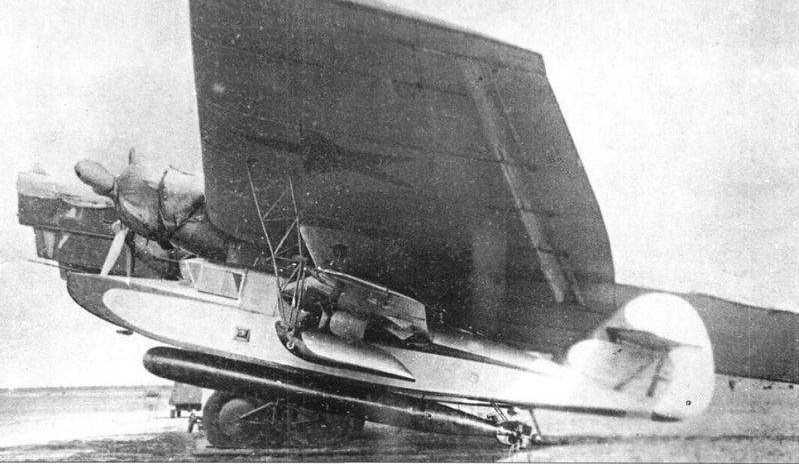
The powerplant consisted of the Bessonov designed 220 hp MM-1 inverted 6-cylinder inline engine, driving a tractor propeller and was located on a faired strut located directly above the fuselage.
The main landers of the landing gear were in the form of consoles that pivoted on the sides of the fuselage to be collected inside the wing by means of a pneumatic system. With the wheels retracted into the wing, the landing gear was exposed as studs, so they were carefully faired. The wheels and structure of the landers were generally similar to those used on the Moscaliov SAM-5-2bis. The tail unit was fixed and was located at the rear of the second rediente.
The monoplane-type tail had stabilizers located high on the empennage.
The cockpit housed two pilots with dual control and featured access through the deck and a drop-down door located on the port side. The passenger cabin had a capacity for 2-3 passengers and access to it was through an opening located in the upper part of the hull, behind the wing.
In general, the SAM-11 had a small load capacity, only 306 kg, with a weight delivery of only 22%, but this was not a limitation considering its conception as a training and liaison aircraft for the VMF.
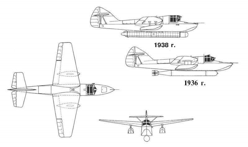
The prototype was completed by Voronezh Institute of Technology by the end of July 1938 and flight tests began in mid-August.
The first flights in a wheeled configuration were successfully carried out by the factory test pilot AN Gusarov. Takeoff and landing tests were performed directly on the runway of the OKB-31 at the factory. During these flights the aircraft demonstrated excellent air handling and good control. The only negative point was the behavior during the approach glide to the runway, when tbufting appeared, which was soon solved by slightly modifying the engine mount. Despite its amphibious configuration, the aircraft demonstrated good speed.
Since the beginning of the flights, a search had been made for a surface of water with the necessary conditions, which was found in the vicinity of Voronezh. They wanted to avoid having to take the plane to the Black Sea (where the naval LII was located) without having carried out at least some initial tests of the model’s behavior in water beforehand.
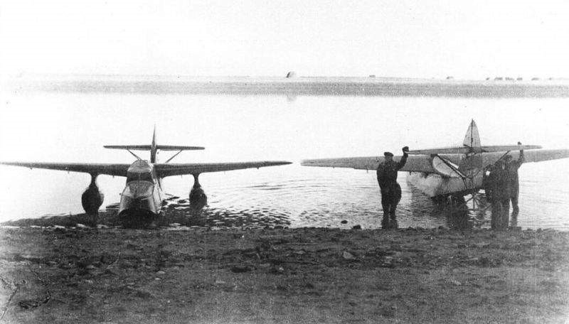
Finally the necessary site was found, a small lagoon not far from the city and large enough to carry out the operations. Tests on water, on the recommendation of the contractor, would be carried out by test pilot P. Ya. Yakovlev, belonging to the Naval Fleet Aviation Flight Research Center (LII VVS VMF). First, the lagoon was explored from the ground and from the air in a Polikarpov Po-2. Later, a group of OKB-31 workers went to the lake to guarantee the necessary conditions: clearing the road to the water, setting up tents for specialists, signage, among others. Lastly, the SAM-11 plane was transferred.
The tests were carried out successfully despite the poor conditions. The SAM-11 took off and landed easily in the water. It was impossible to test the behavior with waves.
Upon returning to Voronezh, the model began to be prepared for the state tests, which were to take place in Sevastopol, at the LII VVS VMF. Finally the plane was sent there together with a group of OKB-31 collaborators, under the direction of LV Polukarov.
The state tests were carried out in the period September-October 1940. As test pilot was selected P. Ya. Yakovlev. The tests on the sea differed considerably from the tests carried out in the calm lagoon and from the first flights with maximum load a tendency to raise splashes was observed, which had to be solved by adding horizontal surfaces to the sides of the bow that deflected the water flow out.
SAM-11 with the wavebreaker mustaches on the sides of the bow.
The tests went smoothly. In the conclusions it was highlighted that the SAM-11 responded to the requirements of a training amphibian and its serial production was requested, also pointing out some difficulties, which had to be corrected in the modified model with a new MV-6 power plant, which would serve basis for series production.
The second prototype, known as the SAM-11bis, rectified the findings made during state testing and introduced a new MV-6 inverted-in-line-6 powerplant, which was the engine selected for series production.
SAM-11bis
Unfortunately, the change of engine, like the Moscaliov SAM-10 bis, did not improve performance, mainly due to the absence of a suitable propeller. The tests were carried out with a fixed-pitch wooden propeller, which due to the higher revolutions of the MV-6 engine, decreased its effectiveness. It was proposed to install a French Ratier metal propeller on the model, but this change was never made.
The SAM-11bis model was not produced for the same reasons as all other models designed to use Renault engines produced in the USSR under license by MV. These engines proved not to be prepared to operate in the harsh winter conditions of the USSR and in 1939 they were taken out of production.
The OKB-31 collective had also worked on a military version in which the second cabin was fitted out to house an artilleryman who operated a pair of ShKAS machine guns. This version had no development.
SAM-11bis with MV-6 engine.
SAM-11 Power plant: 1 x 220 hp MM-1 Wingspan: 11.49 m Wing area: 20.20 m² Length: 8.74m Empty weight: 1094 kg Normal takeoff weight: 1400 kg Wing loading: 64.5 kg/m² Power load: 6.4 kg/hp Load capacity: 2 passengers or 306 kg Maximum speed at sea level: 225 km/h Maximum speed at 2400 m: 240 km/h Takeoff speed: 100 km/h Landing speed: 85km/h Service ceiling: 5600 m Accommodation: 2
SAM-11bis Powerplant: 1 × 220 hp MV-6 Wingspan: 11.49 m Wing area: 20.20 m² Length: 8.74m Empty weight: 1030 kg Normal takeoff weight: 1350 kg Wing loading: 62.0 kg/m² Power load: 6.2 kg/hp Load capacity: 2 passengers or 320 kg Maximum speed at sea level: 217 km/h Maximum speed at 2400 m: 240 km/h Landing speed: 85km/h Service ceiling: 5600 m Time to 3000m: 17.2min Time to 5600m: 1h 03min Range: 900km Landing run: 110m Take-off run: 200m Accommodation: 2
In 1928 Mitsubishi presented to the Imperial Japanese Navy three new types: the Mitsubishi 1MF9 Taka carrier fighter biplane, which featured a French-type avion marin keel; the Type R experimental twin-engine monoplane flying-boat, built also in a civil transport version, both of them based on Rohrbach designs; and the 3MR4 carrier reconnaissance biplane.
The Militi M.B.2 Leonardo is an Italian single-seat powered flying-boat glider version of Militi’s M.B.1 flying-boat glider, designed and built by Bruno Militi.
The Leonardo is a parasol-wing monoplane with a two-step hull and a fuselage of aluminium alloy, wood and fibreglass. The mixed construction wing is supported by two N-struts in the centre and a vee-strut outboard on each side, it has plain ailerons but no flaps. The pilot has an open cockpit with a small windscreen. The 42 hp (31 kW) modified Panhard motor car engine is strut-mounted above the wing centre section and drives a two-bladed fixted-pitch laminated wood pusher propeller.
The aircraft was first flown on 21 June 1970 and was exhibited at the 1972 Turin Air Show.
Engine: 1 × Modified Panhard two-cylinder four-stroke air-cooled motor car engine, 31 kW (42 hp) Wingspan: 8.14 m (26 ft 8½ in) Length: 5.91 m (19 ft 4¾ in) Width: 0.90 m (2 ft 11½½ in) Height: 2.20 m (7 ft 2½ in) Wing area: 11.40 m2 (122.7 ft2) Aspect ratio: 5.7 Empty weight: 145 kg (319 lb) Gross weight: 250 kg (551 lb) Maximum speed: 116 km/h (73 mph) Cruising speed: 80 km/h (50 mph) Stall speed: 55 km/h (34.5 mph) Range: 200 km (124 miles) Endurance: 2 hours 30 min Climb rate: 580 ft/min Service ceiling: 4000 m (13125 ft) Crew: 1
The Militi M.B.1 is an Italian single-seat flying-boat glider designed and built by Bruno Militi. Militi started to build his design for a flying-boat glider in October 1964 and it first flew on 13 August 1967. The M.B.1 is a parasol-wing monoplane with a two-step hull and a fuselage of aluminium alloy, wood and fibreglass. The mixed construction wing is supported by two N-struts in the centre and a vee-strut outboard on each side, it has plain ailerons but no flaps. The pilot has an open cockpit with a small windscreen. From 1969 Militi developed a powered version as the M.B.2 Leonardo which first flew in 1970.
Wingspan: 8.05 m (26 ft 5 in) Length: 5.91 m (19 ft 4¾ in) Width: 0.90 m (2 ft 11½ in) Height: 1.95 m (6 ft 4¾ in) Wing area: 11.40 m2 (122.7 ft2) Aspect ratio: 5.7 Empty weight: 85 kg (187 lb) Gross weight: 165 kg (363 lb) each each Crew: 1
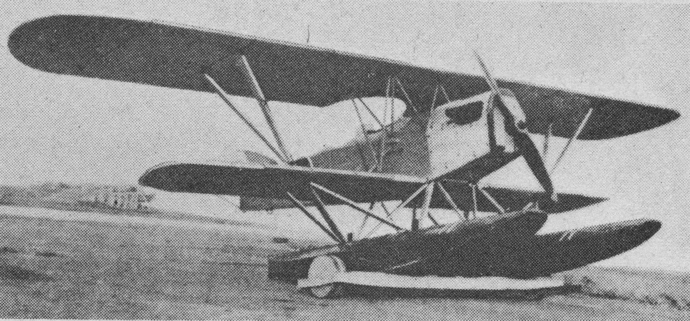
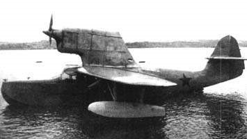
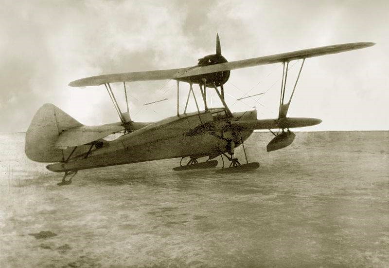
The MU-4 (Russian: Михельсон/Никитин МУ-4) amphibious flying boat was designed and built by NG Mijelson at Leningrad Factory No.23. The initials MU correspond to Morskaya Uchebnaya or Marine Trainer.
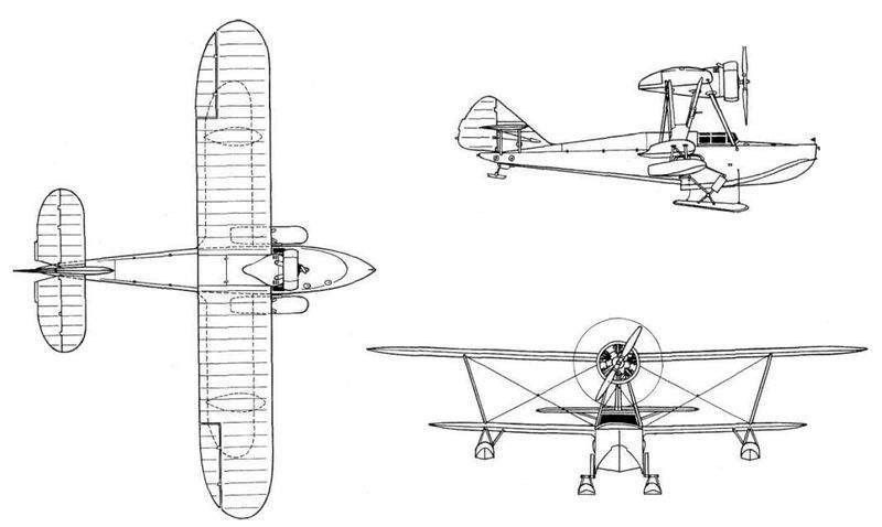
The MU-4 was designed as a flying-boat with a single hull and amphibious capacity. The hull was made entirely of wood and was made up of five watertight departments.
The wing configuration was sesquiplanar with the wing box braced by V-shaped struts made of duralumin. The wooden wing featured a double spar structure with a slim profile and constant chord. The covering was fabric. The lower plane was inserted into the fuselage, while the upper one was located high above the cabin, from where the engine supports started. The drop-shaped stabilization floats were located in the lower wing.
For operations on land, the MU-4 had a conventional landing gear with oleo-pneumatic shock absorbers and a tail skid. The main units retracted forward on the sides of the hull by means of a manual drive system. To allow winter operations the wheels could be replaced by skis.
The MU-4 tested with skis in the winter of 1937 – 1938.
The tail unit was of the conventional monoplane type with the stabilizers located high on the empennage and fixed by parallel struts in its lower part.
The MG-11F engine was installed on the upper wing in a tractor configuration protected by a Townend ring hood and moving a two-blade propeller. For winter, a special “winter” cowl was designed.
The MU-4 could carry two people, seated side by side in an enclosed, dual-control, glazed cabin.
The first prototype was finished in August 1937. Tests showed that the plane had good flight characteristics and could perform aerobatics. During the manufacturing tests this example was destroyed due to a construction defect. The engine fixing brackets to the gunwales were glued with a poor quality glue that ended up coming off. A short time later Mijelson would be imprisoned so the responsibility for further development passed to VV Nikitin.
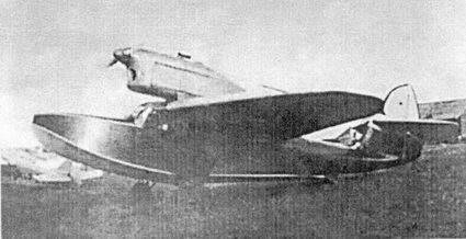
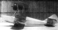
Mijelson MU-4/2 at Factory No.23.
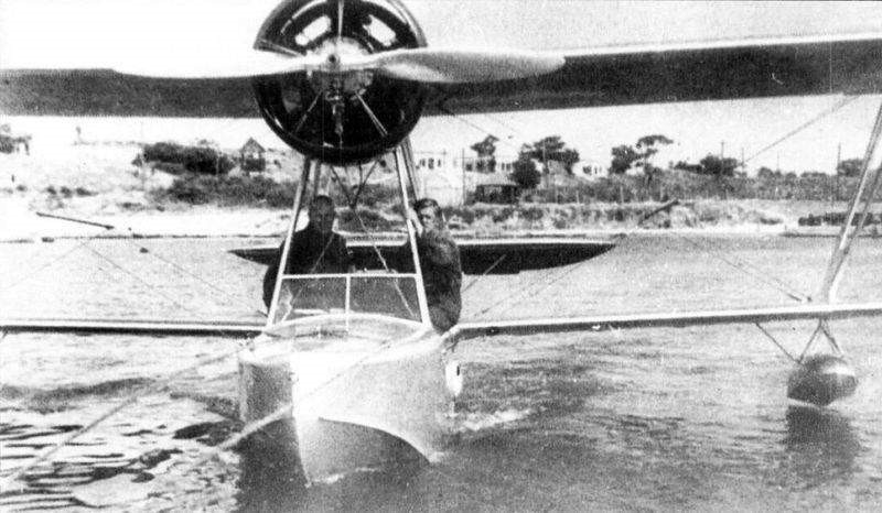
The second prototype was submitted for testing in May 1938. Model tests were carried out at the NII GVF hydrostation located in Konstantinovska Bay in Sevastopol. The flights were carried out by test pilot GI Sergueyev. The MU-4 was presented as a simple plane to fly and capable of taking off and landing in small aquatic spaces.
MU-4/2 during factory tests in 1938.
It was proposed to build a series of 30 examples at Factory No.23, but after Mijelson ‘s conviction this decision was reversed. The Shavrov Sh-2 was produced in series, covering the same needs.
MU-4 Powerplant: 1 x 190 hp MG-11F Wingspan of upper plane: 12.00 m Wingspan of lower plane: 9.00 m Wing area: 33.00 m² Length: 8.70m Height: 3.70m Empty weight: 989 kg Normal takeoff weight: 1255 kg Wing loading: 36.4 kg/m² Power load: 4.2 kg/hp Fuel + lubricant capacity: 80 + 20 kg Top speed: 173km/h Cruising speed: 154 km/h Service ceiling: 3400 m Accommodation: 2
Starting in 1933, a series of projects began to be developed in the USSR under the common name of PSN, acronym for P laner S petsialnovo N aznachenya or Gliders for Special Missions. Among these projects was SF Valk’s idea of using a glider with a torpedo and an infrared or radio guidance system to attack surface ships and naval bases.
This idea had its development in a series of projects known as: LTDD – Letayushaya Torpeda Dalnevo Dieztvya (Long Range Flying Torpedo); DPT – Dalni Planerni Torpedo (Long Range Glider Torpedo); BMP – Bozduzhni Minni Planer (Airborne Mine Glider);
As a development of this conception, Mijelson would receive the task of building an experimental manned hydrofoil glider capable of carrying a torpedo and intended primarily to test remote flight control systems. This glider, called PT, was followed by a small series of copies that received the name PSN (Russian: Михельсон / Никитин ПСН).
The PSN was designed as a small single-seater hydrofoil glider with stabilization floats located approximately halfway across the wingspan of each half plane. The entire construction was made of wood.
The wings presented high implantation with a trapezoidal shape in the plane. Louvered ailerons and flaps were included as control surfaces. The tail unit featured the outriggers braced by double struts high on the keel.
The pilot was located in a glass cockpit in front of the wing leading edge. At the bottom of the glider was fixed a torpedo.
The PSN was carried by a Túpolev TB-3 or TB-7 mother bomber and was released at a pre-calculated height and distances between 30 and 50 km from the target. After launching its torpedo, the glider would land on the water.
A PSN hydrofoil glider with a torpedo under the wing of the Túpolev TB-3 mother plane.
In 1934 the first PT copies and their equipment were built and tested. The first 4 units were built in 1935 at factory No. 23 in Leningrad. In this case, it was a piloted glider version designed to evaluate the infrared guidance piloting system known as Kvant (Quanto). This project was developed under the direction of Mijelson and Nikitin was in charge of the production.
Two PT gliders during the water tests.
From June until October of August of 1936 at the Naval base Krechevits the first fixation tests PT were performed under a bomber Tupolev TB-3. During these tests the PT was piloted by N N. Ivanov.
Between 1937 and 1938 the construction of a small series of PT without a pilot was requested, which received the name PSN (or PSN-1 in some literature).
In general, 10 copies of the PSN-1 were built, which were used in different tests of the Kvant guidance system and an autopilot system developed at that time.
In March 1938, after the arrest of Mijelson, the works were interrupted. All produced copies of the PSN were destroyed.
PSN Wingspan: 8 m Wing area: 13.2 sq.m Length: 8.9 m Height: 2.11 m Empty weight: 970 kg Loaded weight: 1970 kg Speed: 150 – 350 km / h Dive speed: 500 km / h Range: 30 – 35 km Accommodation: 1