NAF SP / Mercury Racer

Al Williams in the 1929 Mercury-Packard Schneider Trophy Racer – did not race

In 1927, Lt. Alford Joseph Williams and the Mercury Flying Corporation (MFC) built the Kirkham-Williams Racer to compete in the Schneider Trophy contest. Although demonstrating competitive high-speed capabilities, the aircraft had handling issues that could not be resolved in time to make the 1927 race. Williams, backed by the MFC, decided to build on the experience with the Kirkham-Williams Racer and make a new aircraft for an attempt on the 3 km (1.9 mi) world speed record.

R. Smith, chief draftsman of the wind tunnel at the Washington Navy Yard, holds a model of the original landplane version of the Williams Mercury Racer. Lt. Al Williams was originally not focused on the Schneider Trophy contest but was later convinced to enter the event.

Although there was no official support from the US government, the US Navy indirectly supported Williams and the MFC’s continued efforts to build a new racer. Williams’ previous racer was designed and built by the Kirkham Products Corporation. However, Williams felt that Kirkham lacked organization, and he was not interested in having the company build another aircraft. Williams had already shipped the previous racer to the Naval Aircraft Factory (NAF) to undergo an analysis on how to improve its speed. With the Navy’s support, the NAF was a natural place to design and build the new racer, which was called the Williams Mercury Racer. The aircraft was also referred to as the NAF Mercury and Mercury-Packard.

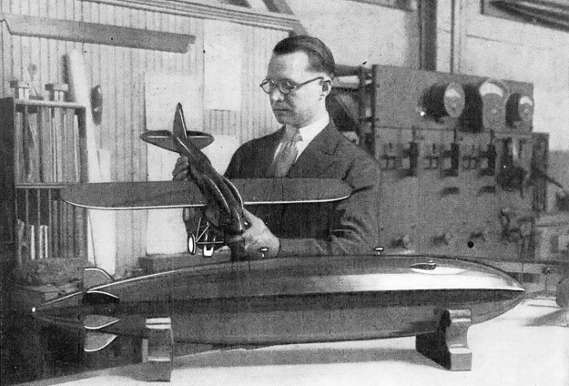
In mid-1928, a model of the Williams Mercury Racer landplane was tested in the wind tunnel at the Washington (DC) Navy Yard. However, the decision was made to design a pair of experimental floats and test them on the aircraft, since there was a pressing need to explore high-speed seaplane float designs. It appears all subsequent work on the aircraft was focused on the seaplane version. Williams did not originally intend the Williams Mercury Racer to be used in the 1929 Schneider race. But the US had won the Schneider Trophy two out of the last four races, and another win would mean permanent retention of the trophy. With the Williams Mercury Racer now a seaplane, Williams relented to pressure and agreed to work toward competing in the 1929 Schneider Trophy contest and to attempt a new speed record.

The Packard X-2775 engine installed in the Williams Mercury Racer was actually the same engine originally installed in the Kirkham-Williams Racer. It has been updated with a propeller gear reduction, new induction system, and other improved components. This engine is in storage at the Smithsonian National Air and Space Museum.

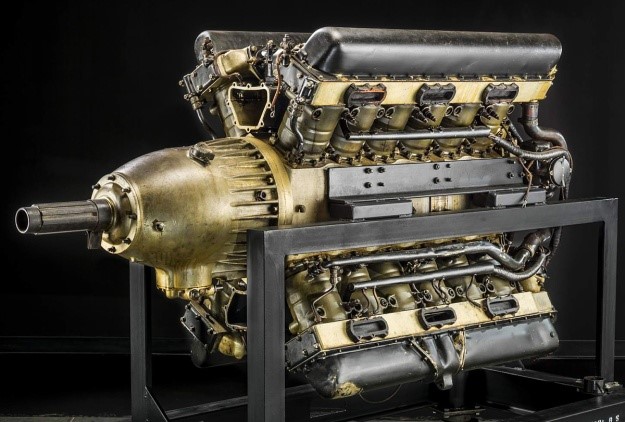
Under the supervision of John S. Kean, work on the racer began in September 1928 at the NAF’s facility in Philadelphia, Pennsylvania. On first glance, the Williams Mercury Racer appeared to be a monoplane version of the previous Kirkham-Williams Racer. While some parts such as the engine mount and other hardware were reused, the rest of the aircraft was entirely new. The Williams Mercury Racer was powered by the same Packard X-2775 engine (Packard model 1A-2775) as the Kirkham-Williams Racer, but the engine had been fitted with a .667 propeller gear reduction, and its induction system had been improved. The 24-cylinder X-2775 was rated at 1,300 hp (969 kW), and it was the most powerful engine then available in the US. The X-2775 was water-cooled and had its cylinders arranged in an “X” configuration.

Packard 1A-2775 Engine No. 1 in its most modified version, with high compression, reduction gear and late type cylinder banks, was used in the Naval Aircraft Factory Mercury racing plane with engine 1A-2775, Serial No. 1, Bureau No. 10960, as a U. S. entry in the 1929 Schneider Trophy.

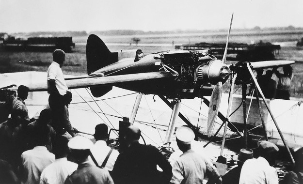
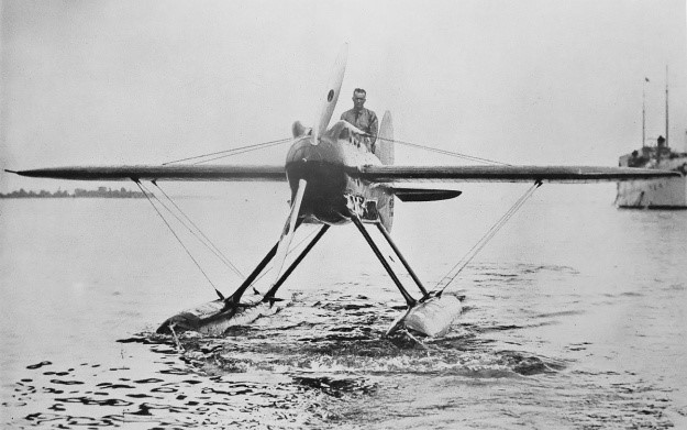
The engine turned a ground adjustable Hamilton Standard propeller that was approximately 10 ft 3 in (3.12 m) in diameter. A Hucks-style starter driven by four electric motors engaged the propeller hub to start the engine. Carburetor air intakes were positioned just behind the propeller and in the upper and lower Vees of the engine. The intakes faced forward to take advantage of the ram air effect as the aircraft flew.

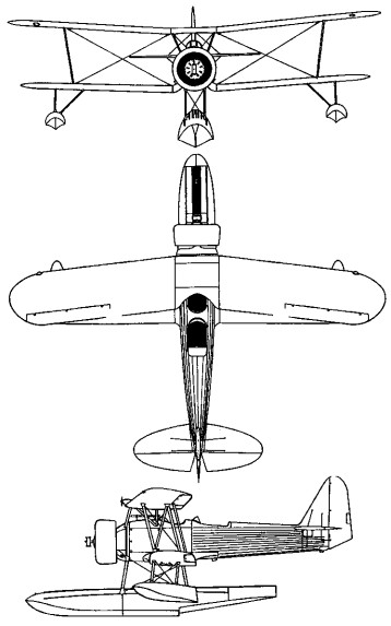
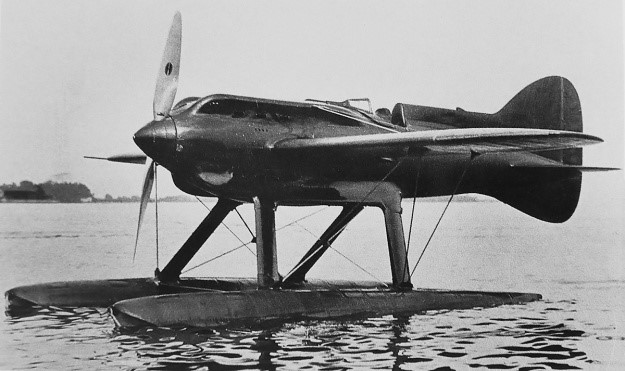
The Williams Mercury Racer consisted of a monocoque wooden fuselage built specifically to house the Packard engine. The racer’s braced mid-wing was positioned just before to cockpit. The wing’s upper and lower surfaces were covered in flush surface radiators. A prominent headrest fairing tapered back from the cockpit to the vertical stabilizer, which extended below the aircraft to form a semi-cruciform tail. A nine-gallon (34 L) oil tank was positioned behind the cockpit. The wings and tail were made of wood, while the cowling, control surfaces, and floats were made of aluminum.

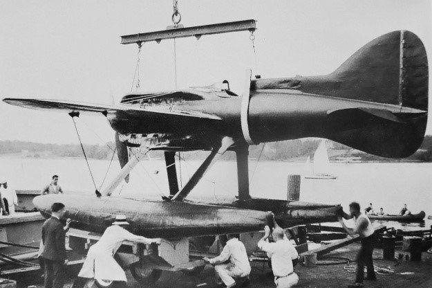
Streamlined aluminum fairings covered the metal struts that attached the two floats to the racer. The underside of the floats had additional surface radiators, which provided most of the engine cooling while the aircraft was in the water at low speed. However, the radiators were somewhat fragile and required gentle landings. The floats housed a total of 90 gallons (341 L) of fuel. Some sources state the fuel load was 147 gallons (556 L). The Mercury Williams Racer had an overall length of approximately 27 ft 6 in (8.41 m). The fuselage was 23 ft 7 in (7.19 m) long, and the floats were 19 ft 8 in (5.99 m) long. The wingspan was 28 ft (8.53 m), and the aircraft was 11 ft 9 in (3.58 m) tall. The racer’s forecasted weight was 4,200 lb (1,905 kg) fully loaded. The Williams Mercury Racer had an estimated top speed of around 340 mph (547 km/h). The then-current world speed record stood at 318.620 mph (512.776 km/h), set by Mario de Bernardi on 30 March 1928.

Lt. Al Williams sits in the cockpit of the Williams Mercury Racer during an engine test. The Hucks-style starter is engaged to the propeller hub of the geared Packard X-2775 engine. Note the ducts above and below the spinner that deliver ram air into the intake manifolds situated in the engine Vees.

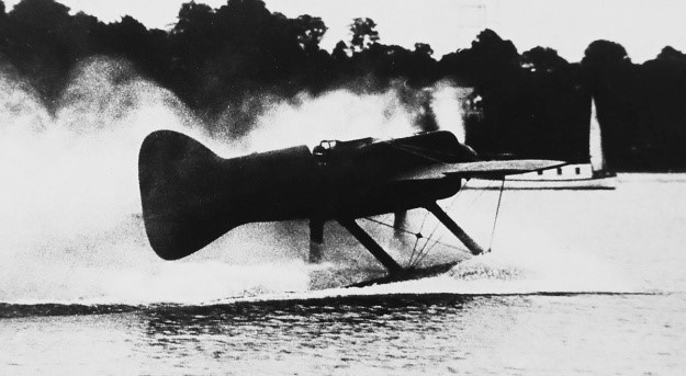
The completed Williams Mercury Racer debuted on 27 July 1929. On 6 August, the aircraft was shipped by tug to the Naval Academy in Annapolis, Maryland for testing on Chesapeake Bay. Initial taxi tests were conducted on 9 August, and a top speed of 106 mph (171 km/h) was reached. The first flight was to follow the next day, and Williams had boldly planned to make an attempt on the 3 km (1.9 mi) world speed record on either 11 or 12 August. To that end, a course had been set up, and timing equipment was put in place. However, it was soon discovered that spray had damaged the propeller. The propeller was removed for repair, and the flight plans were put on hold.

Although not disclosed at the time, the aircraft was believed to be 460 lb (209 kg) overweight. Williams found that the floats did not have sufficient reserve buoyancy to accommodate the extra weight. The spray that damaged the propeller was a result of the floats plowing into the water. Williams found that efforts to counteract engine torque and keep the aircraft straight as it was initially picking up speed made the left float dig into the water and create more spray. Williams consulted with retired Navy Capt. Holden Chester Richardson, a friend and an expert on floats and hulls. Richardson recommended leaving all controls in a neutral position until a fair amount of speed had been achieved. As the aircraft increased its speed, the water’s planing action on the floats would offset the torque reaction of engine and right the aircraft.

The racer being offloaded from the tug and onto beaching gear at the Naval Academy in Annapolis, Maryland. The rudder extended below the aircraft and blended with the ventral fin. Note how the fairings for the lower cylinder banks blended into the float supports.

Weather and mechanical issues delayed further testing until 18 August. Williams lifted the Williams Mercury Racer off the water for about 300 ft (91 m) while experiencing a bad vibration and fuel pressure issues. After the engine was shut down, the prop was found damaged again by spray. Like with Williams’ 1927 Schneider attempt, time was quickly running out, and the racer had yet to prove itself a worthy competitor to the other Schneider entrants. Three takeoff attempts on 21 August were aborted for different reasons, the last being a buildup of carbon monoxide in the cockpit that caused Williams to pass out right after he shut off the engine. Attempts to fly on 25 August saw another three aborted takeoffs for different reasons.

The general consensus was that the aircraft’s excessive weight and insufficient reserve buoyancy prevented the racer from flying. With time running out, one final proposal was offered. The Williams Mercury Racer could be immediately shipped to Calshot, England for the Schneider contest, set to begin on 6 September. While en route, a more powerful engine and new floats would be fitted. It is unlikely that the more powerful engine incorporated a supercharger, as supercharger development had given way to the gear reduction used on the X-2775 installed in the Williams Mercury Racer. The gear reduction was interchangeable between engines, but it is not clear what modification had been done to the second X-2775 engine at this stage of development. Regardless, the improved Mercury Williams Racer would then be tested before the race, and, assuming all went well, participate in the event. However, given all the failed attempts at flight and the very uncertain capabilities of the aircraft, the Navy rescinded its offer to transport the racer to England.

The Williams Mercury Racer was shipped back to the NAF at Pennsylvania. Williams wanted to install the more powerful engine, which had already been shipped to the NAF, and make an attempt on the 3 km record. The Williams Mercury Racer arrived at the NAF on 1 September 1929, but no work was immediately done on the aircraft. The Navy had not decided what to do with Williams or the aircraft. At the end of October, the Navy gave Williams four months to rework the racer, after which he would be required to focus on his Naval duties and go to sea starting in March 1930.

Studies were made to decrease the Williams Mercury Racer’s weight and improve the aircraft’s cooling system. It was estimated that the suggested changes would lighten the aircraft by 400 lb (181 kg). When the four months were up on 1 March 1930, Assistant Secretary of the Navy for Aeronautics David S. Ingalls felt that enough time, effort, and energy had been spent on the racer and ordered all work to stop. Ingalls also ordered Williams to sea duty. This prompted Williams to resign from the Navy on 7 March 1930. Williams had spent nearly all of his savings on his two attempts at the Schneider contest and knew that the MFC and the Navy had also made a substantial investment in the racer. He wanted to see the project through to some sort of completion, even if it did not result in setting any records.

No more work was done on the Williams Mercury Racer. In April 1930, Williams testified before a subcommittee of the Senate Naval Affairs Committee regarding the racer, his resignation, and other Navy matters. During his testimony, he stated that he wanted another year to finish the aircraft. This time frame would have made the racer ready for the 1931 Schneider Trophy contest, but even in perfect working order it probably would not have been competitive. Williams said the aircraft was 880 lb (399 kg) overweight and that this 21% of extra weight was the reason it could not takeoff. The racer actually weighed 5,080 lb (2,304 kg), rather than the 4,200 lb (1,905 kg) forecasted. Williams said he was initially told that it weighed 4,660 lb (2,114 kg), which was 460 lb (209 kg) more than expected. But Williams thought they could get away with the extra weight. It was only when Williams requested the aircraft to be weighed upon its return to the NAF that its true 5,080-lb (2,304-kg) weight was known.

The Williams Mercury Racer being towed in after another disappointing test on Chesapeake Bay. Williams stands in the cockpit, knowing his chances of making the 1929 Schneider contest are quickly fading. Note the low position of the floats in the water.

Williams stated that he wanted to take the Williams Mercury Racer to England even if it was not going to be competitive or even fly. Williams said, “I felt we should see it through no matter what the outcome was. If she would not fly over there—take this, to be specific—I was just going to destroy the ship. It could have been done very easily on the water. I intended to smash it up; but I did intend and [was] determined to get to Europe with it. It made no difference to me what the ship did.”

Ingalls also testified before the committee. He had been involved with the Williams Mercury Racer, was a contributor to the MFC, and had friends who were also contributors. Ingalls said that Williams had informed him about the possibility of crashing the Williams Mercury Racer in England if it was unable to fly. Ingalls said that it was ridiculous to send an aircraft to England that may not be able to fly just so that it could be crashed. It was this consideration that led him to withdraw Navy support for sending the aircraft to England. Ingalls also said that of the aircraft’s extra 880 lb (399 kg), around 250 lb (113 kg) was from the NAF’s construction of the aircraft, and around 600 lb (272 kg) was from outside sources, such as Packard for the engine and Hamilton Standard for the propeller. Ingalls reported that Williams supplied the engine’s and propeller’s weight to the NAF, but those values have not been found. Perhaps the original engine weight supplied to the NAF was for the lighter, direct-drive engine and smaller propeller—the combination installed in the Kirkham-Williams Racer.

On 24 June 1930, the Navy purchased the Williams Mercury Racer from the MFC for $1.00. Reportedly, $30,000 was invested by the MFC with another $174,000 of money and resources from the Navy to create the aircraft. It is not clear if the Navy’s investment was just for the Williams Mercury Racer, as the Packard X-2775 engine was also used in the earlier Kirkham-Williams Racer. The Navy stated they acquired the racer for experimental purposes, but nothing more was heard about the aircraft, and the Mercury Williams Racer faded quietly into history.

Williams taxis the racer in a wash of spray, most likely damaging the propeller again. Note how the floats are almost entirely submerged, especially the left float. The aircraft being very overweight severely hampered its water handling.

NAF PN-12 / Douglas PD-1 / Martin PM-1 / PM-2 / Keystone PK-1

Keystone PK-1

The two PN-12s represented the definitive design. Like its predecessors in the PN-series, the PN-12 was a biplane designed specifically for the patrol/antisubmarine role. Single .30-caliber machine guns were fitted in the bow and amidships, and four 230-pound bombs could be carried under the lower wing. Equally powered by twin 525-hp engines, one PN-12 had twin Pratt and Whitney Hornet R-1850s, and the other Wright Cyclone R-1750s. They gave the aircraft a top speed of 114 mph and a range at cruising speed of just over 1,300 miles. It was flown by a crew of five (in open cockpits), and a relief crew could be carried for long patrols. On 3-5 May 1928, the Cyclone-powered PN-12 set another world seaplane record, covering a distance of 1,243 statue miles in 17 hours, 55 minutes.

The Naval Aircraft Factory was not capable of large-scale production, and the Navy decided to have the PN-12 manufactured by private aircraft companies. Douglas received a contract from BuAer on 27 December 1927 to build twenty-five Naval Aircraft Factory-designed PN-12, under the designation PD-1. Other than the engine nacelles with flat top and bottom profiles, PD-1s were constructed according to the PN-12 specification without variation. The Douglas Aircraft Company produced 25 PD-1 aircraft and the Martin Company built 30 PM-1 variants based on the NAF design.

The first production PD-1s were accepted and placed into service with San Diego-based VP-7 in June 1929. As deliveries proceeded, the type also equipped both VP-4 and VP-6 at Pearl Harbor, Hawaii.

Subsequently, Martin built 25 PM-2 variants and the Keystone Aircraft Corporation built 18 similar PK-1 aircraft, the latter being twin-rudder versions. Thus, the PN-12 gave birth to 98 offspring. These aircraft served in the Fleet until all had ben withdrawn from service by the end of 1936.

In 1927 the Hall Aluminum Aircraft Company developed another PN derivative, the XPH-1. This was the first U.S. Navy flying boat to have all-metal stressed skin construction, which provided a considerable savings in weight. In the event, only ten PH-1s were built as the Navy moved to more advanced flying boat designs. But the Coast Guard procured seven improved Hall PH-2s and seven PH-3s for air-sea rescue missions. Some of these aircraft served into World War II.

Thus, the same basic flying boat design-from the F-5-L to the PH-3-spanned two world wars, a most notable achievement.

PN-12
Engines: 2 x Wright: R-1750D, 525 hp
Prop: 3 blade ground adjustable metal
Max speed: 114 mph
Ceiling: 10,900 ft
Range: 1310 mi
Empty weight: 7699 lb
Loaded weight: 14,122 lb
Span – upper: 72 ft 10 in
Length: 49 ft 2 in
Wing area: 1217 sq.ft
Armament: 2 x .30 mg
Bombload: 4 x 230 lb

Douglas PD-1
5-place naval patrol boat
Engines: 2 x Wright R-1750 Cyclone, 535 hp / later R-1820, 575 hp
Props: 3 blade, ground adjustable metal
Wingspan: 72 ft 10 in
Length: 49 ft 2 in
Wing area: 1162 sq.ft
Max speed: 114 mph
Cruise 94 mph
Ceiling: 10,900 ft
Range: 1309 mi
Empty weight: 8349 lb
Gross weight: 14,988 lb
Armament: 2 x .30 mg
Bombload: 920 lb underwing
Total built: 25

NAF PN-11 / P4N

The PN-11 and P4N were efforts to achieve better perfomance by combining a more streamlined hull with the biplane wings and engines of the PN-12. The new hull was longer, deeper in profile, and approximately 30% narrower in beam. The new hull also introduced a new empenage arrangement
featuring twin fins and rudders on top of a high mounted horizontal staliliser. In 1927 BuAer ordered two aircraft with the new hull as the PN-11, with the same takeoff power as the PN-12, and the first, powered by 525 hp Pratt & Whitney R-1690 Hornet engines, was flown in October 1928, and the second, powered by 525 hp Wright Cyclone, in June 1929. Trials indicated the the PN-11, with the same power as the PN-12, had added a 2500 lb increase in useful load that could mean a 600 mile increase in range.
BuAer placed an order in mid-1929 for three similar aircraft as the XP2N, but changed the designation toXP4N-1 before the first were accepted in December 1930. The XP4N-1 was virtually identical to the PN-11, while the other two, both completed in March 1932 as the XP4N-2s, carried an extra 150 USG of fuel that raised the takeoff weight by 1250 lb. Although the PN-11s and P4Ns never served operationally, the new hull became a key element of new monoplane patrol boats like the XPV/P2Y and 2M/P3M.

NAF PN-9 / PN-10

The subsequent PN-9 (converted from one of the PN-8s) and two newly built PN-10 aircraft were similar to the PN-8. The engines had problems-the Navy always preferred simpler, air-cooled engines-and radial engines were thus used to produce the later PN-12.

The PN-9, however, was a good performer. On 1-2 May 1925, Navy Lieutenants Clarence H. Schildhauer and James R. Kyle, on a test flight over Philadelphia, broke the world endurance record for Class C seaplanes by remaining aloft for 28 hours, 35 minutes, 27 seconds.

The following 1 September, the PN-9 took off from San Francisco for Pearl Harbor. With Commander John Rodgers-Naval Aviator No. 2-in command and navigating, and a crew of four, the aircraft was heavily laden with 1,278 gallons of fuel in its tanks and another 50 gallons in five-gallon cans. The plane nevertheless ran out of fuel and came down several hundred miles short of its destination. Despite an extensive air search, the PN-9 was lost at sea for ten days. Rodgers and his crew, meanwhile, improvised. Relying on their training as sailors, they fashioned a sail out of the lower wing’s fabric and set out for Kauai Island. After covering about 450 miles they were sighted on 10 September by the submarine R-4 (SS-81) about ten miles short of their goal. Still, the aircraft had flown 1,841 statue miles, a record for Class C seaplanes that stood for almost five years.

NAF PN-7

Construction of the PN-7 was begun during 1923, the first being completed in January 1924 and the second in June. While it retained the wooden hull of the PN-5, the PN-7 incorporated an entirely new set of single-bay biplane wings, fabric covered, and metal construction that utilised a muck thicker section USA 27 airfoil in place of the RAF 6 of the PN-5. The increase in lift permitted a significant reduction in both wingspan and area, plus the strength resulting from the deeper spars required only one bay of struts outboard of the engines. In place of the old Liberty engines, experimental Wright T-2 powerplants were tractor-mounted in neat, streamlined nacelles with the water radiators slung under the upper wing centre section.

Trials conducted during 1924 indicated vastly improved performance. Although the wing design was successful, the engines were unreliable, and the wood hull required considerable maintenance.

PN-7
Engines: 2 x Wright T-2, 525 hp
Prop: 2 blade fixed pitch
Armament: 2 x .30 mg
Bombload: 4 x 230 lb
Max speed: 105 mph
Ceiling: 9200 ft
Range: 655 mi
Empty weight: 9637 lb
Loaded weight: 14,203 lb
Span – upper: 72 ft 10 in
Length: 49 ft 1 in
Wing area: 1217 sq.ft

NAF PN-5 / PN-6 / F-6-L

Immediately after World War I, the emphasis in naval aviation was on carrier operations, and patrol-plane development was carried out on a very limited budget. Building on the F-5-L flying boat-developed from the British-designed Felixstowe F.5 aircraft-the Naval Aircraft Factory (NAF) in Philadelphia produced an improved version of the twin-engine flying boat, which was redesignated PN-5 in 1922. 1 The designation PN-6 was used for two modified variants (originally F-6-L). In 1922 the F6L became Naval Aircraft Factory PN-6.

Nakajima MS / E8N

Designed to replace the company’s E4N2 in Navy service, Nakajima’s MS submission was basically an updated version of the E4N2. Of similar biplane configuration, with a central float and underwing stabilising floats, it was powered by a 433kW Kotobuki 2 KAI 1 radial engine, and differed from its predecessor primarily by having revised wings and tail unit.

Seven prototypes were tested from March 1934 and, following evaluation against competing aircraft from Aichi and Kawanishi, the MS was ordered into production in October 1935 as the Navy Type 95 Reconnaissance Seaplane Model 1 (Nakajima E8N1).

An E8N2 with improved equipment and a more powerful engine was introduced before production ended in 1940, when a combined total of 755 had been built by Nakajima (707) and Kawanishi (48).

Used successfully, during the Sino-Japanese War in roles which included artillery spotting and dive-bombing as well as reconnaissance, some were still operating from navy vessels at the beginning of the Pacific war, gaining the Allied codename ‘Dave’. They were soon diverted to second line duties such as communications, liaison and training.

E8N1
Engine: Nakajima Kotobuki II-Kai, 580 hp
Wingspan: 33 ft 0.75 in
Max speed: 183 mph

E8N2
Engine: 1 x Nakajima “Kotobuki-2” KAI 2
Wingspan: 10.98 m / 36 ft 0 in
Length: 8.81 m / 28 ft 11 in
Height: 3.84 m / 12 ft 7 in
Wing area: 26.5 sq.m / 285.24 sq ft
Max take-off weight: 1900 kg / 4189 lb
Empty weight: 1320 kg / 2910 lb
Max. speed: 300 km/h / 186 mph
Ceiling: 7270 m / 23850 ft
Range: 900 km / 559 miles
Armament: 2 x 7.7mm machine-guns, 2 x 30-kg bombs
Crew: 2

Nakajima NZ / NJ / E4N / P-1 Mail / Giyu-11

Nakajima’s first attempt to satisfy the Navy requirement was the E4N1 biplane. This aircraft had a welded chromium molybdenum steel tube structure with fabric covering at the rear and aluminium sheet covering at the front. It was a standard biplane, with fabric covered wings with a wooden structure. The E4N1 was a twin float aircraft, but the two floats were very similar to the Vought design. Bombs were carried on the underside of the fuselage. It was powered by a 420-520hp Nakajima Jupiter VI radial engine, and reached 130mph.

The first prototype Type 90-2 Reconnaissance Seaplane, or E4N1, equal-span biplane reconnaissance aircraft first flew in 1930, company designation NZ. Intended for navy service as the Nakajima E4N1, it had twin floats and an uncowled Kotobuki radial engine.

Two prototypes of the E4N1 were built. They were given the official designation Navy Type 90-2-1 Reconnaissance Seaplane – Aichi had already had a reconnaissance seaplane accepted in 1930, and that became the Type 90-1. The E4N1 was tested by the Japanese Navy early in 1931, but the design was rejected because it wasn’t very manoeuvrable.

A stronger version was produced and in December 1941 was accepted as the Type 90-2-2 Reconnaissance Seaplane, E4N2. It could also be used with wheels, when it became the Type 90-2-3 E4N3.

The NJ or Navy Type 90-2-2 or E4N2, Reconnaissance Floatplane was a complete redesign, with a single main float and twin wingtip stabilising floats and introduced a cowled engine. It closely resembles the US Vought O3U-1 Corsair biplane and, like it, was intended for shipboard use and catapult launching. This time the fuselage structure was a mix of wood and metal. Once again the forward fuselage was metal covered but the rest of the fuselage and the wings were fabric covered. The wings had a wooden structure and were rearward folding.

The E4N2 was much more manoeuvrable than the E4N1. The first prototype was tested late in 1930, suggesting that it was already under development before the E4N1 had been rejected.

Powered by a 336kW Nakajima Kotobuki radial engine, the Type 90-2-2 had a maximum speed of 222km/h and 85 went into service with the Japanese navy as the E4N2 between 1931 and 1933, a version with fixed wheel landing gear going into service as the E4N2-C; 67 of the latter were completed.

E4N2

Nakajima produced eighty E4N2s between 1931 and 1936 and Kawanishi produced another 67 aircraft between 1932 and 1934.

Nakajima also produced five of the E4N2-C carrier variant. This had wheels and carrier arrestor gear. They underwent service trials but weren’t accepted.

In total 153 were built.

In 1933 nine of the E4N2-C landplanes were converted as night mail carriers designated P-1 Mail, for use between the main islands of Japan. A single-seater with the pilot accommodated in an enclosed cockpit.

The E4N2 was the Japanese Navy’s main ship-borne reconnaissance aircraft from 1932 until it was replaced by the Nakajima Type 95 Reconnaissance Seaplane (E8N) in the mid 1930s. It was used on battleships and cruisers and was a popular aircraft with a good combination of manoeuvrability and strength. It saw combat during the Shanghai Incident

In January 1933 Nakajima won a contract for eight mailplanes from Nihon Koku Yuso to fly a new night mail service. Their design, the Nakajima P-1, was based on that of the Nakajima E4N3 (Navy Type 90-2-3), a reconnaissance seaplane. The P-1 was a single seat, landplane biplane of mixed wood and metal structure with fabric covering.

It had two spar, single bay wings with N-form interplane struts between the spars aided by wire-bracing. The central upper wing was joined to the fuselage with outward-leaning cabane struts, inverted Vs to the forward spar and single struts to the rear. The lower wing, slightly shorter in span, was joined directly to the lowest fuselage longerons.

The P-1 was powered by a nose-mounted 420–450 hp (310–340 kW) Nakajima Jupiter VI nine cylinder radial engine though some were later re-engined with the 585 hp (436 kW) Nakajima Kotobuki 2-kai-1, a related nine cylinder radial which had powered the Nakajima E4N3. Both had narrow-chord Townend cowlings. Its cockpit, initially open but enclosed on later aircraft with glazing running aft into a turtle back fairing, placed the pilot well behind the wings. Night flight safety was increased by two landing lights under mid-span and parachute flares. It also had a radio receiver and a radio beacon.

The fuselage was circular immediately behind the large radial engine but became more flat-sided rearwards. The tail was conventional with the tailplane mounted on top of the fuselage carrying elevators with rounded tips and cut-outs for rudder movement. The vertical tail was also rounded, with a full rudder that reached down to the keel.

The P-1 had fixed landing gear with wheels on divided axles, their centres hinged on a short, under-fuselage V-strut pylon. Splayed landing struts and rearward drag struts were mounted on the lower fuselage longerons. The wheels were largely enclosed under narrow helmet fairings.

The first of Nihon Koku Yuso’s eight aircraft was completed in May 1933. The standard night mail route connected Tokyo, Osaka and Fukuoka and began operations in August 1933. Though this service was successful in the sense of increasing mail volume it showed that these night flights were stressful for a single pilot in a single-engined aircraft, especially in bad weather. As a result, the P-1s were gradually retired over two pioneering years, replaced by larger, twin-engined aircraft with a larger crew.

A ninth, specially built, P-1 was used by the Ministry of Communications.

E4N1 / Navy Type 90-2-1 / NZ
two prototypes
twin-float seaplane
Engine: Nakajima Jupiter VI, 420-520hp
Speed: 130mph

E4N2 / Type 90-2-2 / NJ
Engine: 1 x Nakajima “Kotobuki”, 433 kW (580 hp)
Wingspan: 10.98 m (36 ft 0 in)
Wing area: 29.7 m² (319 ft²)
Length: 8.87 m (29 ft 1¼ in)
Height: 3.97 m (13 ft 0 in)
Empty weight: 1,252 kg (2,760 lb)
Loaded weight: 1,800 kg (3,968 lb)
Max speed: 222 km/h / 138 mph
Cruise speed: 148 km/h (80 kn, 92 mph)
Range: 1,019 km (550 nmi, 633 mi)
Climb Rate: 10 min 34 sec to 9,843ft
Service ceiling: 5,740 m (18,830 ft)
Crew: 2
Armament: 1 × fixed 7.7 mm machine gun & 1 × flexible 7.7 mm machine gun
Bombload: 2 × 30 kg (66 lb) bombs
single-float seaplane
85 built

E4N2-C / Navy Type 90-2-3 / NJ
landplane
arresting gear and fixed-undercarriage
67 built

E4N3 / Navy Type 90-2-3 / NJ
Reconnaissance Seaplane

P-1 Mail
9 converted from E4N2-C airframes
Powerplant: 1 × Nakajima Jupiter VI
Propeller: Hamilton Standard fixed pitch metal
Wingspan: 10.97 m (36 ft 0 in)
Wing area: 32.57 m2 (350.6 sq ft)
Airfoil: N-22 upper wing, Clark Y lower
Length: 7.66 m (25 ft 2 in)
Height: 3.70 m (12 ft 2 in)
Empty weight: 1,225 kg (2,701 lb)
Gross weight: 1,992 kg (4,392 lb)
Maximum speed: 243 km/h (151 mph, 131 kn)
Cruise speed: 194 km/h (121 mph, 105 kn)
Range: 1,000 km (620 mi, 540 nmi)
Time to 3,000 m (9,800 ft): 9 m 27 s
Crew: one

Giyu-11
One of the two E4N1 seaplanes converted with a cabin for use by Tokyo Koku Yuso Kaisha between Haneda airport, Shimizu and Shimoda.