Preble-Rekar Airship

A never-completed 250 foot rigid airship, 24 feet in diameter, under construction during 1909-1910 by the Preble-Rekar Airship Company of Portland, Oregon.

Its dimensions were to have been 250 feet in length and 25 feet in diameter. Apparently bankrolled by Oregon investors, the Preble-Rekar Airship Company of C. H. Preble and J. J. Rekar (Rekar of San Francisco, CA), set up shop in Portland. The structure was made of spruce and no nails or bolts were used.

Polzien Blimp

About 1997, Marvin Polzien decided he wanted a homebuilt blimp. There were no quick-build kits for homebuilt blimps, set of plans and a kit of materials for a homebuilt blimp. Marvin, along with friends Dennis Riley and Louie Remondino, decided to design their own. Marvin subleased part of a large military hangar on the Ardmore airport, Oklahoma, and the work began, with other volunteers pitching in.

Their first model was a cylindrical bag of aluminized plastic attached along the bottom to a welded-aluminum truss structure. A simple platform suspended from the truss provided a place for the pilot to sit (in a plastic patio chair) and a place to mount the power unit (a hot-air balloon inflator fan). About that model, Marvin says, “It was a total disaster– the material we used was no good – it leaked like a sieve. We took it out of the hanger once and I made one tethered trip around the ramp, but that was all. Then we deflated it and put it away.”

Using lessons learned from the first model, the team designed the second model. He says, “We just made it up as we went– we didn’t know what we were doing. Our learning curve was pretty wide, so we’ve got a lot of junk lying around that didn’t work.”

The first step was to select a better material for the envelope. Helium is a small molecule that can sneak its way through most materials, so low permeability was a primary requirement. They selected a .009”-thick white heat-sealable polyester plastic with good tear resistance.

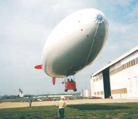
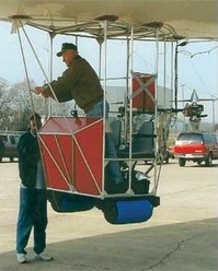
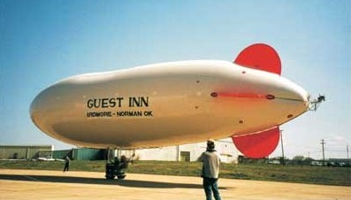
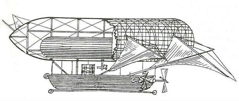
To achieve the desired buoyancy, they decided to make the envelope 82 feet long and 20 feet in diameter, tapered to form a streamlined nose and tail– an estimated 18,000 cu. ft. capacity. A two-place welded-aluminum “car” for a pilot and passenger would be supported from the bottom of the envelope, supported by a “catenary curtain” of suspension lines inside the balloon.

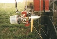
A 12-hp engine/propeller unit mounted on each side of the car would provide the main power. Each engine would be able to tilt up or down to vector thrust for climbing, cruising, or descending.

Pitch and yaw control would be provided by a third engine/propeller unit (24-hp) mounted on a gimbal at the extreme rear of the envelope and controlled from a control stick in the car. Fixed horizontal and vertical stabilizer panels would augment pitch and directional stability.

Inside the envelope would be two “balloonets” – smaller bags inside the large bag immediately forward and aft of the car– that could have air pumped in or out for trim control. Air would be provided from a compressor mounted on one of the engines.

A total of 13 gores of the 60” polyester would be required for the 20-ft diameter. In January 2002, the team laid out the gores on the hangar floor and cut them out. Then they began the monumental task of lapping and heat-sealing the gores together to form the envelope.

In February 2001, the envelope was fully sealed. After a preliminary filling with air (supplied ingeniously by a Shop Vac), the first filling with helium was an adventure. “We tried to fill from the middle first, but suddenly the helium all shifted to the front of the bag and up it went into the rafters! We were lucky we didn’t damage it. Now, we put sandbags across the envelope and fill from the back first. As it fills, the sandbags gradually roll toward the front,” Marvin said.

Of course, with the opportunity to fill with helium comes the necessity to empty it out now and then. But how does one keep from losing $1700 worth of helium? “Simple,” says Marvin, “We just built another storage bag bigger than the envelope and transferred it over!” But, how? “Shop Vac,” he says matter-of-factly. Marvin is a true innovator.

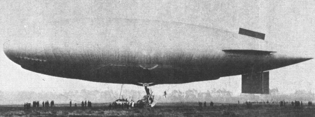
By March, the blimp had been taken outside for its first tethered flight. Finally, on August 3, 2002, the first free flight was accomplished. Watching video of the takeoff, Marvin said, “At that point, I didn’t know doodly about flying that blimp.”

After a short trip around the airport at about 200 feet at what appears to be about 30 mph, the video shows him approaching to land. He continued narrating, “About that time, I was asking myself how I was gonna land! I decided to rotate the engines down to pull me downward, but now I know I can just point the nose down a little to descend.”

Since then, Marvin has flown the blimp “five or six more times– I lose count.” On one flight he had an engine failure and, while trying to restart it, allowed the blimp to drift into some trees, punching a few holes in the envelope.

He has lost the lease on the big hangar and expects to be kicked out at any time. “I don’t know,” he says, “Sooner or later, I’ll have to deflate it, pack it up, and put it in my hangar.”

In December 2009 hundreds watched as a blimp piloted by 79-year-old Marvin Polzien flip flopped across the sky over Ardmore. He says he brought the blimp down near the freeway because a motor that helps steer the blimp failed. “I had three alternatives on how to land that thing. One was in the trees- that was not an option. Next one was in the median on the interstate, which is not good, and the third option which is to just take it up and let the wind blow me northwest of Ardmore,” Polzein said Thursday.

After the members of the FAA showed up wanting to see Polzien’s pilot’s license and medical certificate, which he couldn’t produce, his blimp could be grounded be for good. In order to operate an airship, it must first be certified with the FAA and its operator must have at least a private pilot’s license.

Also working against him is that fact this is not the first time he’s had to make an unscheduled landing. He crashed another home made blimp last May. That same blimp also floated away the next day and managed to make it all the way to North Texas with no one in it.

Polzien, Marvin

Marvin Polzien from Ardmore, Oklahoma, born 1930. Marvin’s interest in flying began early, in a little Iowa country school where he was fascinated with pictures of airplanes in the encyclopedia. His first flight was at age 12 when, defying his mother, he bought a $1 ride in a J3 Cub at a county fair. By 2001 he owned a Piper Malibu DLX, a couple of Bonanza’s, a powered parachute, and a hot air balloon.

Piasecki PA-97 Heli-Stat

The Piasecki PA-97 Heli-Stat project began in the mid 1970s with a view to combining the lift capability of a lighter-than-air vehicle with the precise manoeuvrability of the helicopter, and following support from the US Forestry Service and the US Navy, construction of a prototype Heli-Stat began at Lakehurst, New Jersey, in 1979. The hybrid aircraft uses an airship-based envelope, attached via a skeletal structure to the front fuselage portions of four Sikorsky SH-34J helicopters, each powered by a standard Wright radial engine driving the conventional main rotor system and mounted at the four corners of the aircraft. The tail rotors are replaced by large diameter propellers to provide propulsion and full controllability.

At the beginning of 1984 it was expected that the Heli-Stat would fly in 1985, following a redesign of the structure which had failed under load tests. The following data is provisional

Richard Burke, 29.07.2008
I spent 7 years on this project starting first at the MAIN engineering facility drafting this monster along with 15 other people on Island Avenue in Philadelphia and later moved to Lakehurast during the structural pluck tests. I was there up until the ground manuvering tests where being performed. If you have any questions I can answer them I was over every single part of the airframe / Sh34J’s (Modified) and the aerostat (ZPG2 envelope). [The photo] was a roll out for a photo op dog and pony show note the lack of inverted v fins on the aerostat and the lack of pusher props on the helos also US Forrest Service was not painetd on the envelope yet . I am actually in this photo aft center stern of ship next to the guy with the bike, Joe O’Halleren
It was truly a combination of four SH-34 helicopters and a ZP-3 patrol blimp. It had B-52 landing gear and P-51 reduction gear boxes driving H-3 tail rotors as pusher props.

Piasecki Heli-Stat
Engines: 4 x Wright R-1820-84A, 1525shp
Overall width: 60.05m
Overall length: 74.07m
Empty weight: 24895kg
Gross weight: 50469kg
Maximum speed: 132km/h
Service ceiling: 3810m
Range: 3307km
Range with maximum payload: 80km

Pauly & Egg Fish Airship Dolphin

The creation of two Swiss-borne gunsmiths; eccentric engineer and inventor of the cartridge breech-loader (patented 1812), Jean Pauly, and Durs Egg, gun-maker to King George III – its construction was begun during June 1816 in Knightsbridge, London, and continued into the following year. The rigid craft, Pauly’s second dirigible flying fish – his first being a smaller one that he first flew in 1804 near Paris with little success – had an envelope 90 feet long and was notable for its intended use of trimmable ballast. The device, to have been either a sand-filled box or a water-filled barrel (accounts differ), was to be slung on ropes laid out between the airship’s tail and the rear of the gondola, and by using these ropes the ballast could then be hauled back and forth, thus moving the centre of gravity of the aerostat. For this, and its other innovations in aeronautic navigability, a patent, No.3909 dated April 15, 1815, was granted by the Great Britain Patent Office to Jean Samuel Pauly and Durs Egg. This patent became entangled in a lawsuit between the two gunsmiths, which was ostensibly about pistols. The lawsuit, Egg v. Pauly, lasted from 1817 until 1820 – the year previous to Pauly’s death. During the lawsuit Pauly claimed that Egg had failed to assist with the production of certain firearms in contravention of an agreement dated March 15, 1815, which dealt with the building of the airship. In the end, the venture, aptly named “Egg’s Folly” by those following its lack of progress, failed miserably, proving to be both too complex and too costly, resulting in the financial ruin of its inventors. A decade later, Durs Egg, having gone blind and insane, died in 1831. In January 1844, P. T. Barnum and General Tom Thumb (1838-1883) sailed for England to begin a European tour where at the Surrey Zoological Gardens a captive balloon ascent exhibition was made by the famous dwarf using the Dolphin’s still-existing goldbeater’s skin air bladder, or ballonet rather, capable of lifting fifty or sixty pounds when filled with gas.

Pauly Fish Dirigible Balloon 1804-05

In 1789, Baron Scott, of Paris, proposed an aeronautic fish. Jean Samuel Pauly revived the plan with modifications. Marshal Michel Ney patronised it, and gave nearly 100,000 francs for the construction of an aerostat 50 feet long, and for experiments. Its first trial was made on August 22, 1804 at Sceaux, south of Paris; the success anticipated did not follow.

Patrocínio Aerostato/Dirigivel Santa Cruz

A machine devised by the Brazilian José do Patrocínio. The machine was variously named the Aerostato Santa Cruz or the Dirigível Santa Cruz. It was a mix between lighter and heavier than air. The balloon (hydrogen gas filled) mounted on top of the fuselage lifted the machine in the air, where it paddled along with the “Mississippi-wheels” mounted at the side. To navigate the machine several rudders were installed. It seems the construction at the top were auxiliary wings. Patrocínio started construction in mid-1901, but fate struck as on December 12, 1901 a violent storm hit Rio de Janeiro and destroyed the building hangar completely, killing two of the workforce and wounding five man. In already failing health Patrocínio started all over again, selling everything he had to fund the new project. In the end he lived in a small room next to the building hangar. But his life work was not finished and he passed away in 1905.

Partridge Pneumadrome

This airship appeared in 1848, and was designed by a man named J.M. Partridge. The envelope was cylindrical, tapering at each end, and was composed of a light rigid framework covered with fabric. The envelope was covered with a light wire net, from which the car was suspended. The envelope contained a single ballonet for regulating the pressure of the gas. Planes, resembling sails, were used for steering. In the car, at the aft end, were fitted three propellers driven by compressed air. Several short trips were carried out, but steering was never successful owing to difficulties with the planes and except in calmest weather she may be said to have been practically uncontrollable.

Parseval PL 18

A new non-rigid airship made its first flight in Germany in May 1906: re¬latively small with a volume of only 2300 cu.m (81 224 cu ft), this airship was of technical interest in that the shape of the envelope was maintained by means of pressurized ballonets fore and aft. The craft was to the design of former army officer August von Parseval, later a professor at the Berlin Technical Academy, and improved models con¬tinued to be produced after their con¬struction was transferred from the Motorluftschiff Studiengesellschaft to the Luftfahrzeug Gesellschaft (LFG) organization in June 1913. In this same year an order was placed by the Brit¬ish government for a single example of the improved type, and Parseval PL 18 was delivered for use by the Royal Navy where it received the service designation Naval Airship No. 4 (NA4).

On 5 August 1914 this vessel, by a strange stroke of irony, was the first British aircraft to carry out an active war operation when, flying from its base at Kingsnorth, the first RNAS airship station, it was sent to patrol the Thames Estuary. It was used again on 10 August, this time in company with NA3, the only British airship of the period to be armed, another imported design, an Astra-Torres.

The degree to which Parseval de¬signs had advanced in a short time was evident from the fact that the NA4 was a revised type of vessel, which prob¬ably promoted the order for a further three before the war, to be built under licence by Vickers at Barrow-in¬-Furness. These were given the service designations NA5, NA6 and NA7 at the beginning of their career, which was entirely confined to use for the instruc¬tion of airship crews.

Meanwhile, the NA4 was still em¬ployed on sterner duties, and the first months of World War I found it in use as a submarine hunter, although its effect was entirely psychological, pro¬viding cover for the convoys ferrying troops of the British Expeditionary Force between Dover and Calais.

An order had been placed with the LFG organization for a further three airships of similar design which would have been the PL 19, PL 20 and PL 21 but the outbreak of war prevented their delivery. They would probably also have been used for training, a role to which the NA4 was finally relegated but it is interesting to note that at the time it was in service as a patrol vessel, the German navy had requisitioned the non-rigid PL 6009 August 1914 and also obtained PL 19 on loan on 19 September for sea patrol work over the Baltic from Kiel This was a duty to which they were well suited, being capable of carrying 590 kg (1,301 lb) of bombs and with a maximum flight time of 11 hours.

Type: patrol airship
Powerplant: two 134 2-kW(180-hp) Maybach six-cylinder water-cooled piston engines
Maximum speed 72 kim h (45 mph)
Service ceiling 4000 m (13123 ft)
Range 1000 km (621 miles)
Diameter 15.50 m (50 ft 10.2 in)
Length 94.00 m(308 ft 4.8 in)
Volume 10000 cu.m (353 147 cu ft)