Engine: 1 x 230hp Beardmore-Halford-Pullinger (BHP) 6-cylinder water-cooled in-line Max take-off weight: 1630 kg / 3594 lb Empty weight: 992 kg / 2187 lb Wingspan: 12.50 m / 41 ft 0 in Length: 9.22 m / 30 ft 3 in Height: 3.33 m / 11 ft 11 in Wing area: 56.86 sq.m / 612.04 sq ft Max. speed: 184 km/h / 114 mph Ceiling: 3658 m / 12000 ft Armament: 2 x 7.7mm machine-guns, 4 x 50kg bombs Crew: 2
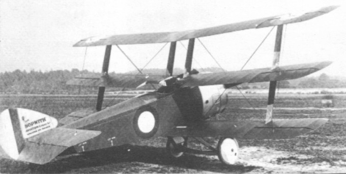
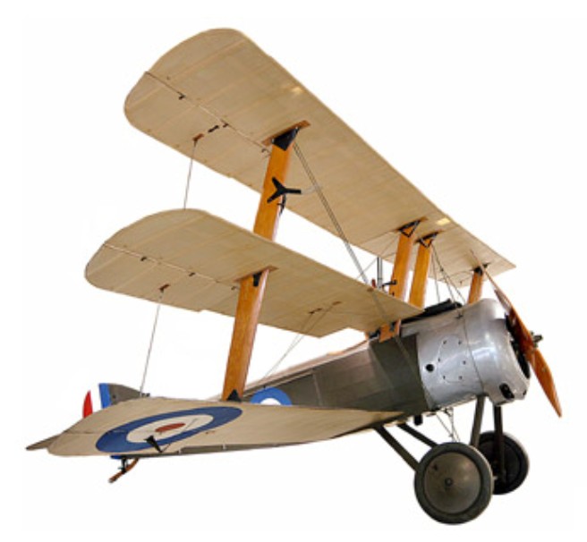
The original Sopwith Triplane, serial N500, was designed as a private venture by Herbert Smith. It had been evolved as a faster-climbing derivative of the Pup, with even better manoeuvrability and improved vision for the pilot. Wing span remained the same as for the Pup, but each wing was of much narrower chord and had an aileron fitted.
The prototype made its first flight on 28 May 1916 with test pilot Harry Hawker at the controls, and so delighted was he with the Triplane’s handling that he looped the aircraft three times within three minutes of taking off.
Both the Royal Flying Corps and the Royal Naval Air Service ordered the type but policy changes led to the Triplane only being used by the Royal Naval Air Service fighter squadrons on the Western Front. The Triplane single-seat fighter was nicknamed ‘Tripe’ or ‘Tripehound’.
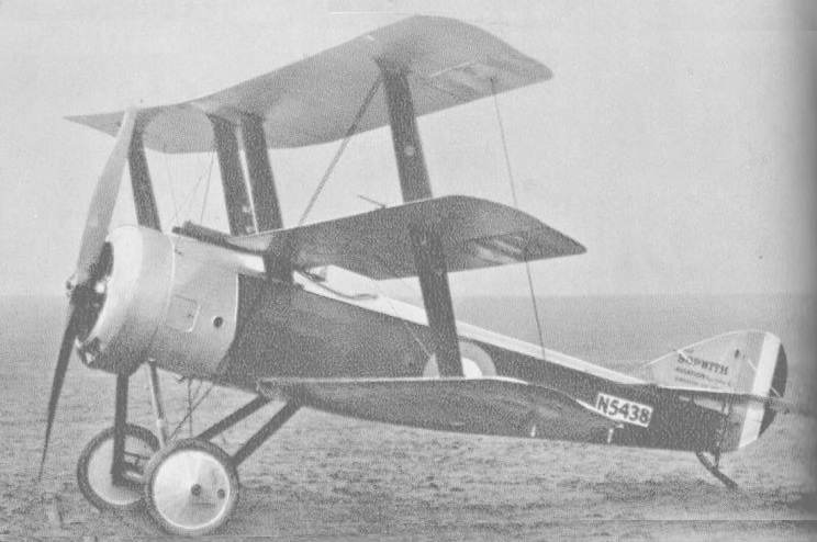
The exact number of Triplanes that became operational with the RNAS is not clear. What is known is that the first prototype was followed by three more fitted with Clerget and Hispano-Suiza engines of 112kW and 149kW. A further 148 aircraft were built, of which five were presented to France, another three were loaned and probably returned, and one went to Russia.
Some production was by Oakley and Co at Ilford.
Initial production Triplanes, with 82kW Clerget rotary engines, had been ordered for the RFC. In the event they were delivered to the RNAS, as were later examples with 97kW Clerget engines fitted and the tailplane span reduced from 10 ft to 8 ft. The last was delivered on 19 October 1917.
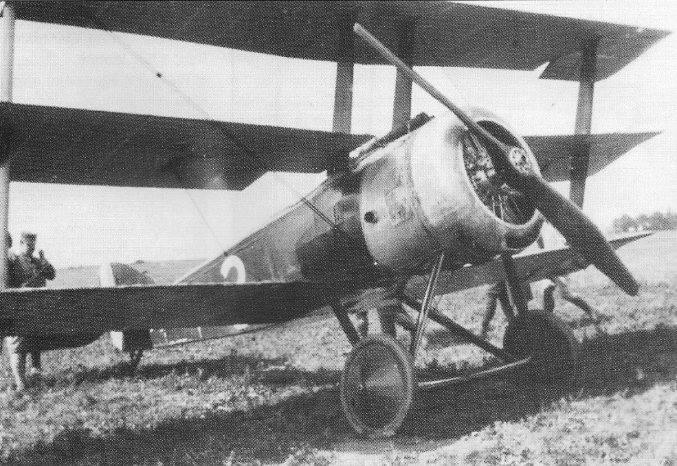
The top exponent of the Triplane was Raymond Collishaw, who commanded ‘B’ Flight of No 10 (Naval) Squadron from April 1917 – a unit which received some of the first Triplanes. Known as the ‘Black Flight’ because of the colour of its Triplanes and the names given to individual aircraft (Black Maria, Black Sheep, etc), it was composed exclusively of Canadian pilots, who accounted for 87 kills between May and July. Collishaw managed to average more than one kill every two days throughout June. He ended the war as the highest-scoring RNAS pilot, with 60 victories.
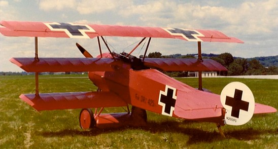
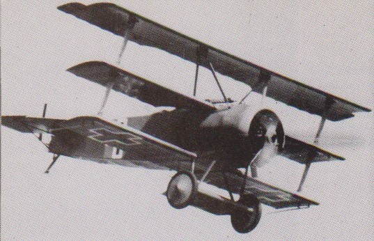
It made such a profound impression on the Germans that a specific request was made to their aircraft manufacturers to design and produce triplane fighters. Only the Fokker Dr1 was built in quantity. The triplane concept had a brief life and in less than two years it had been eclipsed by the new and more powerful biplane fighters on both sides.
Although not so famous as its Fokker counterpart, the Sopwith Triplane achieved impressive success in its brief career, entering service early in 1917 until the autumn of that year, when it was superseded by the Camel. Approximately 150 Sopwith Triplanes were built. No other machine could match its rate of climb, and no other fighter could regularly operate at 6100 m (20,000 ft), a height at which the Triplane frequently patrolled.
Flt. Sub-Lt. Ray Collishaw along shot down 16 German aircraft in 27 days of fighting. His ‘Black Flight’ of No 10 Sqn accounted for 87 enemy aircraft in three months.
A Mr M.Alliot of Godalming, UK, was building an external replica of a Triplane, 80% complete in 1974. It was to be powered by a Lycoming O-290-3 and serialed N5487. It was offered for sale in April 1975 and almost certainly bought by Phillip Mann and taken to Booker for competition.
John S. Penny of Sheffield, UK, was building and external replica in conjunction with Northern Aeroplane Workshops (who were building their own replica). Built to Sopwith plans, it was underway by June 1974, registered with the PFA as 21-10035.
Engine: 1 x Clerget 9 Z, 130 hp / 96kW Length: 18 ft 10 in. (5.72 m.) Wing span: 26 ft 6 in (8.07 m) Height: 3.1 m / 10 ft 2 in Wing area: 24.6 sq.m / 264.79 sq ft Weight empty: 1,100 lb (500 kg) Max take-off weight: 699 kg / 1541 lb Fuel capacity: 20 Imp Gal. Max speed: 117 mph (190 kph) Ceiling: 20,500 ft (6,250m) fully loaded Endurance: 2.75 hours Range w/max.fuel: 450 km / 280 miles Seats: 1 Armament: One 7,7mm Vickers machine gun, firing forward
Engine: Clerget 9B, 130 hp Wingspan: 26 ft 6 in Length: 18 ft 10 in AUW: 1540 lb Max speed: 117 mph
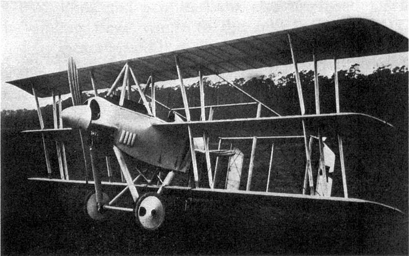
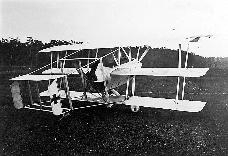
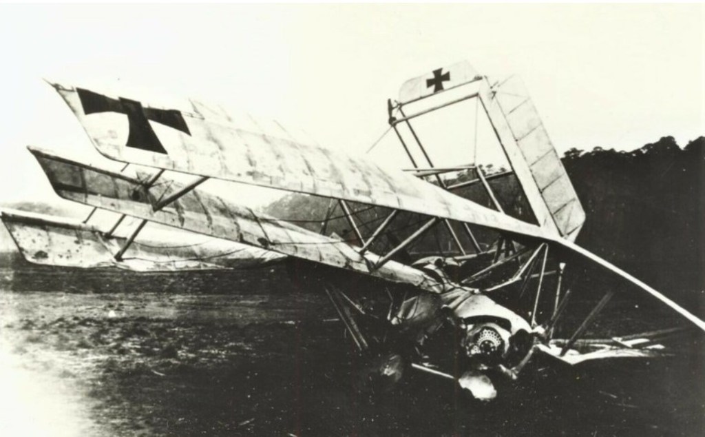
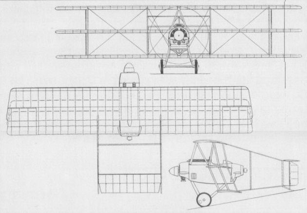
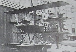
The Siemens-Schuckert DDr.I was a World War I German twin engine, push-pull configuration triplane fighter aircraft.
The DDr.I was one of the first aircraft to have two engines on the same centre line, one in tractor configuration and the other a pusher. It was a triplane with constant chord, straight edged, square tipped wings of equal span and marked stagger. These were divided into two bays by pairs of near-parallel interplane struts. The upper wing was braced over the fuselage with a pair of N-form struts, leaning inward from the upper fuselage to common mountings on the wing centre line. The middle wing of the triplane was positioned at shoulder height on the fuselage and the lower wing passed unbraced below. There were short span ailerons on each wing.
The smoothly faired and contoured short fuselage of the DDr.I positioned the open pilot’s cockpit between two 110 hp (82 kW) Siemens-Halske Sh.I nine cylinder rotary engines, one with a two blade tractor propeller and the other driving a four blade pusher turning just aft of the lower wing trailing edge. The empennage was mounted on four longitudinal, tubular outrigger beams, braced with vertical and transverse members. There were no fixed rear surfaces; the single piece, constant chord elevator reached between the two upper beams and a pair of similarly shaped rudder went from the upper to the lower beams, hinged further aft than the elevator but with their lower ends on a hinged frame that moved with it. The DDr.I had a fixed conventional undercarriage, with its mainwheels on a single axle mounted on wide spread V-struts attached to the lower fuselage at the lower corner points of each engine’s firewall.
Engine control problems and a lack of stability experienced in the first flight, made on 9 November 1917, led to a crash; the aircraft was not rebuilt and plans for a more powerful version, the DDr.II, powered by two 160 hp (119 kW), Siemens-Halske Sh.III eleven cylinder rotary engines were abandoned.
Powerplant: 2 × Siemens-Halske Sh.1, 82 kW (110 hp) each Propellers: 2/4-blade; the tractor propeller had two blades and the pusher four. Wingspan: 10.9 m (35 ft 9 in) Wing area: 30 m2 (320 sq ft) Length: 5.8 m (19 ft 0 in) Empty weight: 680 kg (1,499 lb) Gross weight: 910 kg (2,006 lb) Crew: One Armament: 2×7.9 mm (0.311 in) calibre LMG 08/15 (Spandau) synchronised machine guns
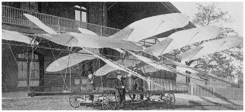
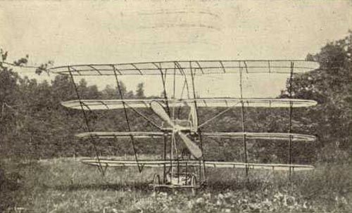
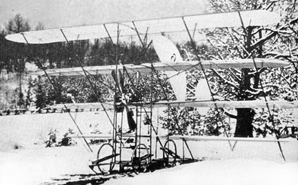
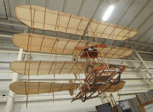
Built and flown by Matthew B. Sellers in somewhat different versions during 1908 and 1913. Engines used were a Kemp G-2 two-cylinder engine of 16 hp and an 8 hp Dutheil-Chalmers.
Sellers Quadruplane No.6
Based on his previous multi-wing glider experiments, the no.6 was originally was a glider with spring-actuated, variable-incidence wings. First flying on 28 December 1908, it flew successfully as late as 1927 with an economy of power, the largest motor being a 10hp two-cylinder Bates, the four positive-staggered wings of 36″ chord provided more than 200sqft of wing area. One built, it was the most prominent of Sellers’ 52 different designs in 22 years to 1914. Of note is a claimed feature invented and used by Sellers as early as June 1908, a four-wheel gear that rose automatically when the plane left the ground, with landings then made on skids. Aircraft empty weight shown in US Patent Office Gazette 11 July 1911 was 110 lb.
Replica
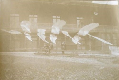
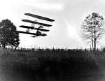
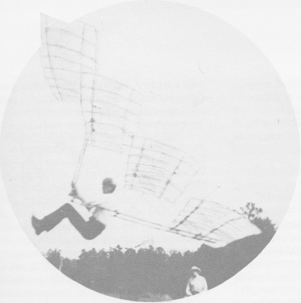
In 1910 Matthew Sellers flew in a 4 hp quadruplane at Grahn, Kentucy. The plane weighed less than 80 lb and was powered with a Duthell & Chamers two cylinder opposed engine.
Circa 1927, Mathew B. Sellers bult and flew multi-plane gliders. These gliders flew well and Sellers went on to fly a steped, quadraplane glider in which each successively lower wing was spaced a chord behind the leading edge of the upper surface.
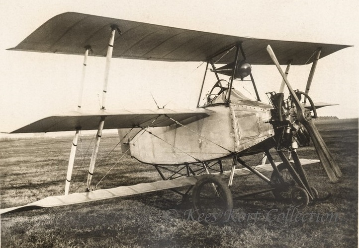
The Sarri Triplano named the ‘Vampiro’ (Vampire) was an unconventional tailless triplane design of engineer Sarri. It came too late to participate in the 1920 Italian ultralight competition, held in Taliedo (Italy).
A triplane, which according to the rules of the contests had to be less than 6,00 m, the engine was an Anzani radial, rated at 35 hp.
It was an unconventional design, with the wings set into a heavy stagger. The tail section had no elevators. The undercarriage had a two-wheel nosewheel and no tailwheel or tailskid.
Not ready when the contest started, nothing was heard of this machine and its designer Sarri since.
Ron Sand built a Fokker Dr.1 replica in 1970, then making plans available for home builders. A metal, wood, tube and fabric full-size replica with all the original detailing. Engine options include Warner 145-185hp and Lycoming 150-180 hp.
The replica drawings are high quality Construction prints, not to be confused with the average homebuilt drawing which usually lack detail on method and parts. The drawings are printed from ink on mylar tracings which result in excellent quality blueprints and show every part as close to full size as possible – with part numbers, specifications and descriptions.
Complete set contains 31 sheets (24″ x 36″) highly detailed prints include a 14 page (8-1/2″ x 11″) materials list. The plans show the complete installations of LeRhone (rotary), Warner (radial) and Lycoming (opposed) engine. This allows that any engine can be removed and changed with a different type at any time by just removing the engine mount bolts and bolt in the other engine. The drawings are complete with instructions on building the jigs required for construction of the wing spars and ribs, with step-by-step assembly instructions. All of the original full size Fokker DR-1 details are shown. Many of these details never presented before or lost by previous artists. For example: Complete LeRhone engine installation Warner engine installation with all plumbing and controls Lycoming opposed engine installation Original Carl Bamberg compass Spandau machine guns Original control stick with throttle and gun-trip levers Hydraulic brakes are shown for safety but the brake system has been designed not to interfere with the original appearance and is actually an add-on feature to the rudder-bar and can be removed at any time. Both the original tailskid and steer-able tail-wheel are shown for your choosing and safety. The only changes made are in the interest of safety of the pilot and reliability of the aircraft. In addition to the brake system, some of the primary fittings and hardware have been increased in size without a weight penalty. Since we are not carrying 150 lbs. of guns and ammunition, it is wise to use some of the weight allowance in making the aircraft stronger and more reliable. The replica Fokker DR-1 is not a difficult aircraft to build nor does it have to be an expensive project providing you don’t rush construction and use common sense in purchasing materials.
Wing Span: 23.50 ft Length: 19.0 ft Max. Gross Wt: 1,600 lb Empty Wt: 1,150 lb Fuel Capacity: 22.5 Usgal Range: 250 sm Takeoff Dist: 300 ft Landing Dist: 200 ft Vmax: 120 mph Vcr: 110 mph Vs1 (stall clean): 42 mph Climb Rate @ msl: 1,800 fpm Serv. Ceiling: 15,000 ft Seats: 1 Cabin width: 28.0 in
Engine: LeRhone, 110 hp HP range: 125-200 Height: 9.4 ft Length: 19.02 ft Wing span: 23.6 ft Wing area: 201.8 sq.ft Fuel cap: 22.5 USG Weight empty: 949 lb Gross: 1406 lb Speed max: 120 mph Cruise: 110 mph Range: 250 sm Stall: 42 mph ROC: 1800 fpm Take-off dist: 300 ft Landing dist: 200 ft Service ceiling: 15,000 ft Seats: 1 Landing gear: tail wheel or skid