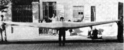
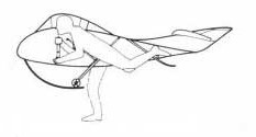
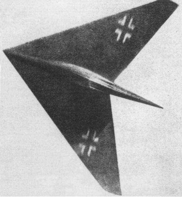
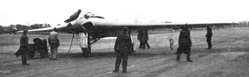
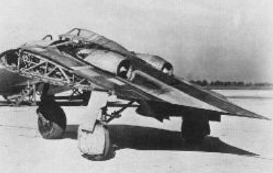
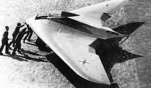
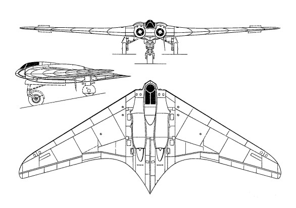
The first Alita designed by Reimar Horton was built by a group of enthusists in Argentina in 1953. It was destroyed in a storm.
The version B was then built, which never flew, and is in the aeronautical museum of moron Buenos Aires, Argentina.
HXa Wing area: 11.2 m² Wing span: 7.54 m Hang glider weight: 39 kg Minimum pilot weight: 75 kg Maximum pilot weight: 75 kg Maximum speed: 150 km/h Max glide ratio: 30 Max glide ratio speed: 50 km/h Maximum speed: 170 km/h Max glide ratio: 18 Max glide ratio speed: 78 km/h Landing speed: 42 km/h
HXb Wing area: 17.5 m² Wing span: 10 m Hang glider weight: 39 kg Minimum pilot weight: 75 kg Maximum pilot weight: 75 kg Maximum speed: 150 km/h Max glide ratio: 20 Max glide ratio speed: 60 km/h Landing speed: 36 km/h
HXc Wing span: 15 m Hang glider weight: 42 kg Minimum pilot weight: 90 kg Maximum pilot weight: 90 kg Maximum speed: 150 km/h Max glide ratio: 30 Max glide ratio speed: 50 km/h Landing speed: 39 km/h
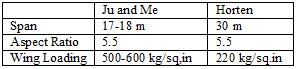
In February 1945 a committee under Professor Bock with representatives from Junkers, Messerschmitt and Horten, deliberated over the optimum design for a 4 jet engined bomber. Designs by Junkers (Ju 287. A swept forward tailed aircraft), Messerschmitt (Project 1107 as swept back tailed aircraft), and Horten (swept back tailless) were considered, and a joint report issued giving the committee’s opinion on the best estimate for relative performance. Junkers published the report. The specification to be noted was for 900 kph at 10 km height and a range of 3,000 km using four H 11 jets. According to Horten the committee decided that his machine, given the same top speed as the others would have more range and less landing speed. (125 kph against the 175 kph for the others.) Alternatively he could carry 8 tons (metric) of bombs against the 4 by his competitors for the same range. The dimensions of the aircraft were roughly as follows:
Horten said the agreed CDo for this aircraft was 0.0078 excluding Mach number correction. In the structural design he reckoned to save 6% of the all up weight (spar and rib weight) compared with the conventional type. He thought the committee a bit unfair because they insisted on increasing his estimate of structure weight by about a ton. All the above figures were remembered by Horton, who used them as a rough illustration. They are not accurate.
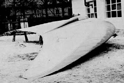
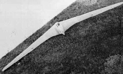
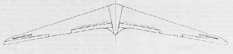
According to Reimar Horten this planform is theoretically the most efficient and has the minimum induced drag. The validity of the theory is not known. The glider was constructed in a burst of enthusiasm but proved rather awkward to make because of its curves and was damaged during transport and never flown.
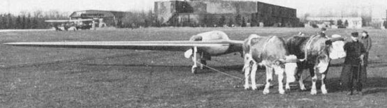
This was a sports sailplane designed to conform to the 1939 Olympic Games specification. It was designed for simplicity and ease of production. The first aircraft was built from sketches and proper drawings for the production type were made later with slight modifications. Construction was carried out at Hersfeld. Span was 15 m and aspect ratio 16.2. The wing had 23 degree leading edge sweep and 8.6 degree total twist. Sections were 4% camber and 17% thickness at the root with 10% thick symmetrical tips. Empty weight was 120 kg giving a flying weight of 225 kg. Controls consisted of one Frise nose elevon per side with rudders and dive brakes of H IV design. The glider trimmed at CL=1.0 with elevons neutral. The pilot was put in a prone position as on the H IV and the undercarriage arrangement was also similar but for the replacement of the rear skid by a wheel.
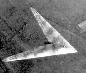
As part of their program on high sweepback, the Hortens built the Ho.XIII to give flight test results on a leading edge sweep of 60 degrees. This increase of sweep reduced the aspect ratio to four. Control deflections were all doubled to compensate for the obliquity of the hinge line and the ends of the control flaps trimmed to run parallel to the new aircraft center line. The pilot had to be carried in an underslung nacelle to give him a reasonable view; the control column was inverted and hung from the roof of the nacelle. Undercarriage consisted of a main wheel inset in the nacelle and a fixed nosewheel mounted on a welded steel tube fork. Flying the H XIII totaled about 10 hours. Trials were interrupted in the middle by Scheidhauer landing in a barbed wire fence. CLmax was found to be 0.9, with the stick right back. In this condition the incidence was larger than expected – about 20 – 25 degrees instead of 15 degrees, but Horten thought that the induced drag was not correspondingly increased. It was thought that the wing was not completely stalled with the stick hard back because the CG was too far forward. Control was moderately satisfactory, but in spite of the increased elevon travel was inclined to be sluggish. Elevator control particularly was much less sensitive than on other Horten aircraft.
Horten H XIII a Wing span: 12m Wing area: 36sq.m Empty Weight: 250kg Payload: 80kg Gross Weight: 330kg Wing Load: 9.2kg/sq.m Aspect ratio: 4 MinSink: 1.1 m/s 60 kph L/DMax: 16 80 kph Seats: 1
The H XII was a light side by side two seater with a 100 hp engine. It was intended as a private owners coupe but R.L.M. were interested in it as a trainer. The first of the type was built and flown at Gottingen (where it was found destroyed in June this year) as a glider; work was also in progress at Kirtorf (sp.) where a mock up of the power center section was found, badly damaged by fire. The wing used a Mustang section at the root graded to a symmetrical section with Mustang fairing shape at the tip. Washout was 3 – 3.5 degrees. Elevon controls were of H VII type with a 20% Frise nose. Plain flaps were fitted with a H IX center section spoiler and “trafficator” drag rudders. The undercarriage was unusual in having two wheels forward and one main wheel aft taking 60% of the weight. All three wheels were retractable. Little flying had been done, but it was found that the same troubles were arising as on the H IVb. The laminar flow sections were causing bad tip stalling and loss of control effectiveness at the stall.
Span: 10 m Aspect Ratio: 8 Wing Area: 32 sp./m (345 sp.ft.) Leading Edge Sweepback: 30 deg Weight: 700 kg (1,550 lb.) Wing Loading: 2.19 kg/sq.in. (4.5 lb/sq.ft.)
The H X was a high speed arrow shaped flying wing inspired by Busemann’s statement in 1936 of the beneficial effect of sweepback on delay of the shock stall. This apparently cheered up the Horten brothers and gave them new proof that they were working on the right lines. Initial work on the H X consisted of experiments with flying models of 10 ft length weighing about 8-10 kg. From these they deduced the CG position needed for satisfactory flight with low aspect ratio and high sweepback, and found that they got good results with 4 degree dihedral and no fin area. The next step was a man carrying glider model weighing 400 kg. The wing section was a symmetrical D.V.L. low drag type with maximum thickness at 45% chord. Wing washout was 12 degrees, dihedral 4 degree. Small Frise nose elevons were fitted but no flaps; a trimmed CLmax of 0.8 was expected with a stalling incidence of 20 – 25 degrees. Rudder control was to be by wing tip “trafficators”. The undercarriage was of tricycle layout giving zero ground incidence but clearance for a 15 degree nose up attitude at takeoff; the front wheel was to be retractable but the rear wheels fixed.
Work on the glider H X was in progress at Hersfeld. On June 4, 1945 it was being used as an M.T. servicing depot and all aircraft components had been dumped in a basement. Only one wing rib and the main spar could be found. All drawings and calculations had gone. After an exploration of low speed control problems on the glider, the next step was to have been a power version with an Argus AS 10C pusher engine. The final development was envisioned as a jet propelled aircraft, with the same general dimensions, weighing 6-7,000 kg. A single H 11 jet engine was proposed and a top speed of 1,200 kph was expected with 1,300 kg thrust; the thrust was to be improved to 1,500 kg. Initial tests on control effectiveness with high sweep were carried out on the H XIII to guide the control design for the H X. No ideas for controls on the final version had emerged but Horten said he intended to stick to Frise nose balance as long as it would work. In general appearance the H X bears resemblance to the Lippisch designs for high speed and supersonic aircraft, particularly the P 13. Horten said he had not heard of Lippisch’s work in Vienna until he came to London. The main difference in design is that Hortens think a fin unnecessary whereas Lippisch favors a very large one.
Horten H X (H XIII b) Wing span: 7.2m Wing area: 37.8sq.m Empty Weight: 600kg Payload: 100kg Gross Weight: 700kg Wing Load: 18.5kg/sq.m Aspect ratio: 1.4 L/DMax: 9.0 97 kph MinSink: 2.0 m/s 88 kph Seats: 1
In 1943, Reichsmarschall Göring issued a request for design proposals to produce a bomber that was capable of carrying a 1,000 kilograms (2,200 lb) load over 1,000 kilometres (620 mi) at 1,000 kilometres per hour (620 mph); the so-called “3×1000 project”. Conventional German bombers could reach Allied command centers in Great Britain, but were suffering devastating losses from Allied fighters. At the time, there was no way to meet these goals—the new Junkers Jumo 004B turbojets could provide the required speed, but had excessive fuel consumption.
The Hortens concluded that the low-drag flying wing design could meet all of the goals: by reducing the drag, cruise power could be lowered to the point where the range requirement could be met. They put forward their private project, the H.IX, as the basis for the bomber. The Government Air Ministry (Reichsluftfahrtministerium) approved the Horten proposal, but ordered the addition of two 30 mm cannons, as they felt the aircraft would also be useful as a fighter due to its estimated top speed being significantly higher than that of any Allied aircraft.
Horten IX
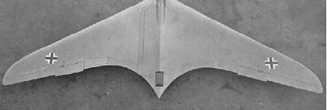
The H.IX was of mixed construction, with the center pod made from welded steel tubing and wing spars built from wood. The wings were made from two thin, carbon-impregnated plywood panels glued together with a charcoal and sawdust mixture. The wing had a single main spar, penetrated by the jet engine inlets, and a secondary spar used for attaching the elevons. It was designed with a 7g load factor and a 1.8× safety rating; therefore, the aircraft had a 12.6g ultimate load rating. The wing’s chord/thickness ratio ranged from 15% at the root to 8% at the wingtips. The aircraft utilized retractable tricycle landing gear, with the nosegear on the first two prototypes sourced from a He 177’s tailwheel system, with the third prototype using an He 177A main gear wheelrim and tire on its custom-designed nosegear strutwork and wheel fork. A drogue parachute slowed the aircraft upon landing. The pilot sat on a primitive ejection seat. A special pressure suit was developed by Dräger. The aircraft was originally designed for the BMW 003 jet engine, but that engine was not quite ready, and the Junkers Jumo 004 engine was substituted.
Control was achieved with elevons and spoilers. The control system included both long-span (inboard) and short-span (outboard) spoilers, with the smaller outboard spoilers activated first. This system gave a smoother and more graceful control of yaw than would a single-spoiler system.
The first two of the type were built at Gottingen.
Four aircraft of the H IX type were started, designated V.1 to V.4.
V.1 was the prototype, designed as a single seater with twin B.M.W. 109-003-1 jets, which were not ready when the airframe was finished. It was accordingly completed as a glider with fixed tricycle landing gear and extensively test flown at Oranienburg during the summer of 1944. D.V.L. instrumented it for special directional damping tests to determine its suitability as a gun platform. First flown on 1 March 1944, flight results were very favorable, but there was an accident when the pilot attempted to land without first retracting an instrument-carrying pole extending from the aircraft.
The design was taken from the Horten brothers and given to Gothaer Waggonfabrik. The Gotha team made some changes: they added a simple ejection seat, dramatically changed the undercarriage to enable a higher gross weight, changed the jet engine inlets, and added ducting to air-cool the jet engine’s outer casing to prevent damage to the wooden wing.
Göring believed in the design and ordered a production series of 40 aircraft from Gothaer Waggonfabrik with the RLM designation Ho 229, even though it had not yet taken to the air under jet power. The first flight of the H.IX V2 was made in Oranienburg on 2 February 1945. All subsequent test flights and development were done by Gothaer Waggonfabrik. By this time, the Horten brothers were working on a turbojet-powered design for the Amerika Bomber contract competition and did not attend the first test flight. The test pilot was Leutnant Erwin Ziller. Two further test flights were made between 2 and 18 February 1945. Another test pilot used in the evaluation was Heinz Scheidhauer (de).
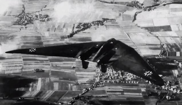
The H.IX V2 reportedly displayed very good handling qualities, with only moderate lateral instability (a typical deficiency of tailless aircraft). While the second flight was equally successful, the undercarriage was damaged by a heavy landing caused by Ziller deploying the brake parachute too early during his landing approach. There are reports that during one of these test flights, the H.IX V2 undertook a simulated “dog-fight” with a Messerschmitt Me 262, the first operational jet fighter, and that the H.IX V2 outperformed the Me 262. Two weeks later, on 18 February 1945, disaster struck during the third test flight. Ziller took off without any problems to perform a series of flight tests. After about 45 minutes, at an altitude of around 800 m, one of the Jumo 004 turbojet engines developed a problem, caught fire and stopped. Ziller was seen to put the aircraft into a dive and pull up several times in an attempt to restart the engine and save the precious prototype. Ziller undertook a series of 4 complete turns at 20° angle of bank. Ziller did not use his radio or eject from the aircraft. He may already have been unconscious as a result of the fumes from the burning engine. The aircraft crashed just outside the boundary of the airfield. Ziller was thrown from the aircraft on impact and died from his injuries two weeks later. The prototype aircraft was completely destroyed after 2-hours flying.
V.3 was being built by Gotha at Friedrichsrodal as a prototype of the series production version. The V3 was larger than previous prototypes, the shape being modified in various areas, and it was meant to be a template for the pre-production series Ho 229 A-0 day fighters, of which 20 machines had been ordered. The V3 was meant to be powered by two Jumo 004C engines, with 10% greater thrust each than the earlier Jumo 004B production engine used for the Me 262A and Ar 234B, and could carry two MK 108 30 mm cannons in the wing roots.
Work had also started on the two-seat Ho 229 V4 and Ho 229 V5 night-fighter prototypes, the Ho 229 V6 armament test prototype, and the Ho 229 V7 two-seat trainer. The Ho 229 V4 two-seat all-weather fighter, was in construction at Friedrichroda, but not much more than the center-section’s tubular framework completed as was the Ho 229 V5 two-seat all-weather fighter. The Ho 229 V6 projected definitive single-seat fighter version with different cannon, mock-up was in production at Ilmenau.
The Ho 229 A-0 projected expedited production version based on Ho 229 V6 was not built. The H.IXb (also designated V6 and V7 by the Hortens) projected two-seat trainer or night-fighter; not built.
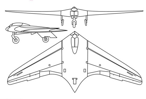
In shape, the H IX was a pure wing with increased chord at the center to give sufficient thickness to house the pilot and the jet units, which were placed close together on either side. The H IX started as a private venture and the Hortens were very anxious to avoid failure so they avoided aerodynamic experiments wherever possible. A lower sweepback was used than on the H V and H VII and laminar flow wing sections were avoided as a potential source of trouble. Wing section at the junction with the center sections was 14% thick with maximum thickness at 30% and 1.8% zero Cmo camber line. At the centerline thickness was increased locally to 16% to house the crew. The tip section was symmetrical and 8% thick. Horten also believed that since the compressibility cosine correction to drag was based on the sweepback of the maximum thickness line, the ordinary section would show little disadvantage. Wing twist was fixed by consideration of the critical Mach number of the underside of the tip section at top speed. This gave a maximum washout of 1.8°. Having fixed this, the CG was located to give trim at CL = 0.3 with elevons neutral. In deciding twist for high speed aircraft, CD values were considered in relation to local CL at operational top speed and altitude (10 km in the case of the H IX). Twist was arranged to give minimum overall drag consistent with trim requirements. The wing planform was designed to give a stall commencing at 0.3 to 0.4 of the semi-span. Wing structure comprised a main spar and one auxiliary spar or wooden construction with ply covering. The center section was built up from welded steel tube. Wing tips were all metal. The undercarriage was completely retractable and of tricycle type the front wheel folding backwards and the main wheels inwards. The nose wheel was castering and centered with a roller cam. When resting on the ground, wing incidence was 7° and the nose wheel took about 40% of the total weight.
The jet engines were installed at -2° to the root chord and exhausted on the upper surface of the wing at 70% back from the nose. To protect the wings the surface was covered with metal plates aft of the jet pipe and cold air bled from the lower surface of the wing by a forward facing duct and introduced between the jet and the wing surface. The installation angle was such that in high speed flight the jest were parallel to the direction of flight. Lateral and longitudinal control was by single stage elevon control flap with 25% Frise nose and compensating geared tap balance. (This system was also used on the H VII, see para. 4.6.) The pilots control column was fitted with a variable hinge point gadget, and by shifting the whole stick up about 2” the mechanical advantage could be doubled on the elevons for high-speed flight. Directional control was by drag rudders. These were in two sections, slight movements of the rudder bar opening the small (outboard) section and giving sufficient control for high speed. At low speeds when courser control was necessary the large movement also opened the second spoiler, which started moving when the small one was fully open. By pressing both feet at once, both sets of spoilers could be operated simultaneously; this was stated to be a good method of steadying the aircraft on a target when aiming guns. The Hortens stated that the spoilers caused no buffeting and claimed an operating force of 1 kg for full rudder, with very little variation in speed. A change was made from the original H VII parallel link system to improve the control force characteristics. With the new system, aerodynamic forces could be closely balanced by correct venting of the spoiler web, leading the main control load to be supplied by a spring. The cover plate of the spoilers was spring loaded to form an effective seal with the rudders closed; this device was used on most Horten spoiler and dive brake designs. On further models of the H IX it was proposed to fit the “trafficator” type rudder tried experimentally on the H VII.
Landing flaps consisted of plain trailing edge flaps (in four sections) on the wings, with a 3% chord lower surface spoiler running right across the center section, which functioned as a glide path control. The outer pair of plain flaps lowered 27° and the inner pair 30° – 35° on the glider version V.1. On V.2 mechanical trouble prevented the inner pair operating and all flying was done with the outer pair only. The center section spoiler could be used as a high speed brake and gave 1/3 g at 950 kph. No dive recovery flap was considered necessary. Proper performance tests were not done on V.2 before its crash and top speed figures were calculated values, checked by Messerschmitts. The following figures were remembered by Reimar Horten: All Up Weight, Including Ammunition and Armour: 8,500 kg (18,700 lbs.) All Up Weight, Excluding Ammunition and Armour: 7,500 kg Wing Area: 52 sq.m (566 sq.ft.) Wing Loading: 33 lb./sq.ft. Fuel (I2 Crude Oil): 2,000 kg (4,400 lbs.) Performance at 7,500 kg (16,500 lbs.) Takeoff Run: 500 m Takeoff Speed (10 deg Flap): 150 kph (95 mph) (Note: This corresponds to a CL of 1.30 which is the stated stalling CL of the aircraft.) Top Speed (at Sea Level): 950 kph (590 mph) (CDo estimated to be 0.011) Calculated ceiling was 16 km (52,000 ft). Engines would not work above 12 km as the burners went out. Rate of Climb at Sea Level: 22 m/sec (4,300 ft/min) In tests against the Me 262 speeds of 650-700 kph (400-430 mph) were obtained on about 2/3 throttle opening. This appears to be the only flight test figure available. Messerschmitt sent performance calculators to the Horten works to check their estimates. The method suggested by D.V.L. for getting the sweepback correction to compressibility drag was to take an area of 0.3 x the root chord squared at the center section as having no correction applied, and then apply full cosine correction over the outer wing. Sweepback angle was defined as that of the quarter chord locus. Test data was available for CDv. for zero sweepback. The Messerschmitt method was to base sweepback on the max t/c locus and to scale Mach number by the square root cos Ø. The H IX V.1 was flown by Walter Horten, Scheidhauer and Ziller. Scheidhauer did most of the flying (30 hours) at Oranienberg, Horten and Ziller flew for about 10 hours. D.V.L. instrumented the aircraft for drag and directional stability measurements. No drag results were obtained because of trouble with the instrument installation – apparently an incidence measuring pole was fitted which could be lowered in flight and glide path angle was obtained from the difference between attitude and incidence measurements. One day they landed without retracting the pole. Directional oscillation tests were completed successfully and an advance report was issued (10 pages of typescript) by Pinsker and Lugner fo D.V.L. The essence of the results was that the lateral oscillation was of abnormally long period – about 8 sec. At 250 kph and damped out in about 5 cycles. At low speeds the oscillation was of “dutch roll” type but at high speed very little banking occurred. Many fierce arguments took place at D.V.L. on desirable directional stability characteristics, the Hortens naturally joining the “long period” school of thought. They claimed that the long period would enable the pilot to damp out any directional swing with rudder and keep perfectly steady for shooting. It was found that by using both drag rudders simultaneously when aiming, the aircraft could be kept very steady with high damping of any residual oscillation. Lateral control was apparently quite good with very little adverse yaw.
Longitudinal control and stability was more like a conventional aircraft than any of the preceding Horten types and there was complete absence of the longitudinal “wiggle” usually produced by flying through gusts. Tuft tests were done to check the stall but the photographs were not good enough for much to be learned. Handling was said to be good at the stall, the aircraft sinking on an even keel. There seems to be some doubt, however, as to whether a full stall had ever taken place since full tests with varying CG and yaw had not been done. Although the stick was pulled hard back, the CG may have been too far forward to give a genuine stall. Directional stability was said by Scheidhauer to be very good, as good as a normal aircraft. He did not discuss this statement in detail as he was obviously very hazy about what he meant by good stability and could give very little precise information about the type and period of the motion compared with normal aircraft. Scheidhauer had flown the Me 163 as a glider and was obviously very impressed with it; he was confident enough to do rolls and loops on his first flight. We asked him how the H IX V.1 compared with the 163; he was reluctant to give an answer and said the two were not comparable because of the difference in size. He finally admitted that he preferred the 163 which was more maneuverable, and a delight to fly (he called it “spielzeug”).
The H IX V.2 with two Junkers 109-004B-1 jet engines was flown at Oranienburg only by Ziller and completed about 2 hours flying before its crash. The redesigned Ho IX V2 demonstrated speeds of up to 960km/h before it was destroyed. This occurred after an engine failure – the pilot undershot, tried to stretch the glide and stalled. One wing must have dropped, for the aircraft went in sideways and Ziller was killed. Before the crash a demonstration had been given against an Me 262; Horten said the H IX proved faster and more maneuverable, with a steeper and faster climb.
In spite of the crash, Horten thought the single engine performance satisfactory and said the close spacing of the jets made single engined flying relatively simple. Such promise encouraged the RLM to instruct Gothaer Waggonfabrik to assume development of the design, and a third prototype, the Go 229 V3, was produced with 1000kg thrust Jumo 109-004C turbojets, but was prevented from flying by the end of hostilities in May 1945.
V3
Work had also started on the two-seat Go 229 V4 and Go 229 V5 night-fighter prototypes, the Go 229 V6 armament test prototype, and the Go 229 V7 two-seat trainer, No progress had been made on 20 pre-production Go 229A-0 fighter-bombers, on order at the end of the war, that were intended to carry two 1000kg bombs and four 30mm MK 103 cannon.
Production was assigned to the Gothaer Waggon Fabrik, which main facilities were placed in the city of Gotha. An initial contract for 20 pre-production aircraft was awarded to the firm and works begun. The Gotha engineers introduced several and extensive modifications to adapt the design to the series production. The construction was subcontracted to the Ortlepp Möbel Fabrik at Friedrichroda. This was a logical solution as the GWF facilities had all their capabilities compromised in the production of parts for other aircraft manufacturers. Besides its management was pushing the RLM to adopt their flying wing designs and this way cancel the Horten IX series production. The Gotha designs were known as the Gotha P-60 with three different versions A, B and C. When the Ortlepp Works at Friedrichsroda were overrun by troops of the American 3rd Army’s VII Corps on April 14, 1945 they found inside of the building three FW in different construction stages: The V3 was nearly complete. The jet engines were installed and most part of the works on the skin had finished.
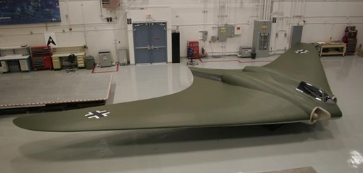
After the end of the war, the V4 and V5 disappeared. In some reports they are briefly mentioned but it’s quite likely that they were scrapped. The V1, the non-powered prototype, was also destroyed and last seen at Kassel Rothwesten airfield. We do not know where in Europe the V3 was taken, where it was crated and loaded in a ship. According to the NASM the HMS Reaper packing list is not known, but there were other vessels with war booty that left Europe. What is sure is that the V3 was shipped to the USA and arrived by train to Freeman. Today, the Horten IX V3 is in store at the Garber Building 22 awaiting a restoration.
Ho-IX V2 Engine: 2 x 2 x Jumo-004, 900kg Take-off weight: 6900 kg / 15212 lb Empty weight: 4844 kg / 10679 lb Wingspan: 16.76 m / 55 ft 1 in Length: 7.46 m / 24 ft 5.75 in Height: 2.6 m / 8 ft 6 in Wing area: 52.8 sq.m / 568.33 sq ft Max. speed: 960 km/h / 597 mph Crew: 1
Horten Ho 229A / V3 manufacturer’s estimates Powerplant: 2 × Junkers Jumo 004B turbojet, 8.7 kN (1,956 lbf) each Wingspan: 16.76 m (55 ft 0 in) Wing area: 50.20 m² (540.35 ft²) Length: 7.47 m (24 ft 6 in) Height: 2.81 m (9 ft 2 in) Empty weight: 4,600 kg (10,141 lb) Loaded weight: 6,912 kg (15,238 lb) Max. takeoff weight: 8,100 kg (17,857 lb) Maximum speed: 977 km/h (estimated) (607 mph) at 12,000 metres (39,000 ft) Service ceiling: 16,000 m (estimated) (52,000 ft) Rate of climb: 22 m/s (estimated) (4,330 ft/min) Wing loading: 137.7 kg/m² (28.2 lb/ft²) Thrust/weight: 0.26 Armament: 2 × 30 mm MK 108 cannon Bombload: 2 × 500 kilograms (1,100 lb) bombs / R4M rockets Crew: 1
Go 229A 0 Engines: two 1000 kg (2,205 lb) thrust Junkers Jumo 109 004C turbojets. Maximum speed 1000kph (621mph) at 6100 m (20,015 ft) Landing speed 130 kph (81 mph) Maximum take off weight: 8500 kg (18.739 lb) Wingspan 16.78 m (55 ft 5/8 in) Length 7.47 m (24 ft 6 1/8 in) Wing area: 51.5sq.m (554.36 sq.ft). Armament: four 30 mm MK 103 cannon and up to 2000 kg (4,409 lb) of bombs.
This was to have been a flying model of a proposed six-engined trans-Atlantic passenger transport weighing 100,000 kg. The span was to be 40 m with an aspect ratio of 10 and sweepback of 28 degrees. Power units were six Argus AS 10 C engines. To make the aircraft attractive to R.L.M. and thus get backing for the project, the Hortens added a rear loading cargo carrying body with an internal space approximately 14’ x 10’ x 6’; this was not part of the design for the full size aircraft. With construction under way, another modification was made (but not disclosed to R.L.M.). This consisted of removing the nose of the cargo body, replacing the nose wheel by wheels on either side of the body and putting a large venturi tube with a 2m x 2.7m throat inside to form a flying wind tunnel. They expected to get about 500 mph airspeed in the throat combined with low turbulence – this they proposed to check by the sphere drag method. Later they hoped to be able to test models of their aircraft which could be made of wood because of the absence of dust in the airstream. Construction was proceeding at Gottingen and was 50% complete at the cessation of hostilities. The steel tube framework for the venturi center section was finished. Estimated Weight and Performance Figures Max. all up weight as a wind tunnel: 9,000 kg Max. all up weight as a cargo carrier
Without takeoff assistance: 15,000 kg
With rocket assisted takeoff: 20,000 kg At 23,000 kg the sea level rate of climb at full power would be zero. At 9,000 kg rate of climb at 180 kph was expected to be 6.5 – 7 m/sec. Estimated trimmed CLmax’s were:
No Flaps: 1.4
With Flaps: 1.6
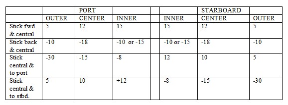
CL for Takeoff: 1.1 The design of the wing and controls was similar to that of the Horten IV. Washout was 7 degrees, to give trim without elevator deflection at cruising CL. Elevons were the three stage type with 35% Frise nose on the outer flap, and 22% on the middle and inner flaps. Compensating geared tabs which could also be used a longitudinal trimmers were fitted to the inner flaps. Maximum control deflections were a follows: (Note: All figures in degrees)
Trailing edge split flaps with a constant chord of 80 cm were to be fitted between the engines. Drag rudders were of the H VII “trafficator” type with vent hole balance plus spring centering. Projection was about 1 meter. Wing Root thickness is about 16%, with the usual reflexed center-line, graded to an 8% symmetrical tip section. Wing structure was in seven parts; a welded steel center section with pilot and co-pilots seat and three outer wooden wing panels per side. The wooden structure was of single spar D-tube form with subsidiary trailing edge ribs. At the factory in Gottingen the center section was found in a semi-complete state, D-noses for the inboard wing panels were finished and spars and ply noses for the outer panels were under construction. Much of the work on components such as engine bearers, petrol systems, undercarriage etc., had been completed and the six engines were in crates at the works, with one spare. Unfortunately all drawings had been taken and many of them seem to have been buried by Horten employees near Kilenburg, in the Russian sector. The fixed main wheels were arranged in tandem pairs on either side of the fuselage and took 85% of the static weight of the aircraft. The castering nose wheel was retractable on the cargo version and had to be mounted on a stalky strut because of the high wing layout. Static ground incidence was 2.5 degrees.
Ho-VIII Max take-off weight: 8000 kg / 17637 lb Empty weight: 5000 kg / 11023 lb Wingspan: 40 m / 131 ft 3 in Length: 16.5 m / 54 ft 2 in Height: 3.85 m / 12 ft 8 in Wing area: 146 sq.m / 1571.53 sq ft Max. speed: 280 km/h / 174 mph Range w/max.fuel: 6000 km / 3728 miles Crew: 3