HWL Pegaz

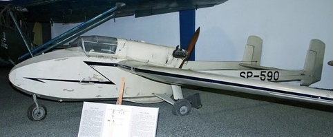
HWL Pegaz SP-590

During 1945 and 1946, Tadeusz Chyliński took part in a competition of the Civil Aviation Department for developing a training motor glider. He won first prize for his project, the HWL Pegaz motor glider. From 1946 to 1947, Tadeusz Chyliński based on an agreement with the Department of Civil Aviation (Departament Lotnictwa Cywilnego) with the help of Bronisław Żurakowski, developed the construction plans for the “Pegaz”. The motor glider was designed to train class “C” glider pilots in stand-alone (without dual-controls) motor piloting, as well as for training and pursuing aeronautic sports in inexpensive aircraft.

The engine for the “Pegaz” was designed by Stefan Gajecki, who was well known for designing skimming boat motors. Construction began on the “Pegaz” at the HWL (Harcerskie Warsztaty Lotnicze – Scouts’ Aircraft Works) in Warsaw.

In 1948, the work was taken over by Warsaw’s Gocław Aircraft Plant 6. The motor glider (one for flying and two unassembled) was finished in spring of 1948. The engineless plane was on display at the Aviation Day in 1948.

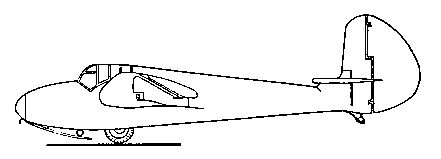
It is a dual-boom monoplane with pusher propeller, three-wheel landing gear with forward steerable wheel, all wood construction. The fuselage is composed of a laminated-wood-sheathed pod containing an enclosed cabin, the engine and two lateral laminated-wood-sheathed boom joining the wing with the directional and diving rudder. The fuselage pod is hexagonal. The instrument panel is fitted with an airspeed indicator, altimeter and vertical speed indicator, a magnetic compass, turn indicator, ignition switch and fuel pump. The cabin also features an air throttle valve and decompressor, a fuel gauge and fuel valve. The motor glider is steered by a stick and rudder bar. The pilot’s seat is made to accommodate a backpack parachute.

The wooden cantilever wing is sheathed in laminated wood and canvas. The wing is a right-angle trapezoid with rounded tips and has three structural sections: a central section and two removable outer sections joined to the central section by three pins. The dual-spar central section is unitized with the fuselage pod and tail booms. The removable monospar outer sections have an oblique auxiliary spar. The canvas-sheathed slotted ailerons are aerodynamically-compensated, differentially displaced 30° upward and 18° downward. The wing has a fixed slot at the edge of attack.

The twin vertical tail is located at the boom tips. The elevator unit is located between them. The monospar fins are sheathed in laminated wood. The control surfaces on the wooden frame are canvas-sheathed.

The three-wheel landing gear has a forward steerable wheel. The main landing gear is tri-strutted with rubber-string shock absorbers. The wheel tires are low-pressured. The aft of the fuselage pod between the wheels is protected against major deflection of the landing gear by an ashwood skin with an inner-tube shock absorber.

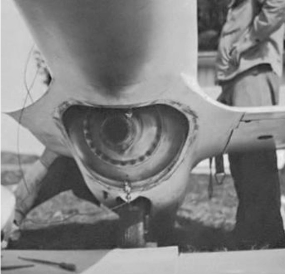
The motor glider is powered by an XL-GAD prototype engine. It is a four-cylinder flat two-cycle air-cooled engine. Two cylinders have a decompressor to facilitate startup. The wooden pusher propeller has a fixed pitch and diameter of 1.42 meters. The 30-liter fuel tank is located to the fore of the engine.

The “Pegaz” was painted a cream color. The wing’s edge of attack, registration number and fuselage arrow were painted navy blue.

“Pegaz” was test-flown on July 16, 1949, piloted by Bronisław Żurakowski and Jerzy Szymankiewicz. The factory and certification test were conducted at the National Aviation Institute in Warsaw and completed in May 1950. “Pegaz” was in three air shows on Aviation Day in 1949, 50, 51.

The “Pegaz” proved to be very safe and easy to pilot during testing and operation. It was stable in every axis with the controls released. By stalling and releasing the stick with the engine running, the motor glider was able to make about decreasing changes in velocity, going into a fixed climb rate of 1.5 m/s with a trajectory speed of 90 km/h. Also by stalling and releasing the stick with the engine throttled, the velocity amplitude changed two to three times, after which the aircraft went into a fixed glide at a speed of 110 km/h and a descent rate of 2.0 m/s. When stalled with the rudder released, the motor glider displayed no tendency to spin. It was hard to get the “Pegaz” to go into a tailspin. The speed necessary to go into a tailspin was 55 km/h, with an altitude loss at one spin of 75 meters. Landing speed was 130 km/h. The motor glider performed acrobatic figures with a gravity load range up to 4 g. It could do loops at a speed of 125 km/h without losing altitude and ended loops with the same speed. The “Pegaz” behaved totally normal in dives at 210 km/h.

At first, the plan was to build 80 “Pegaz” planes for various flying clubs. “Pegaz” passed the National Approval Test with a very good rating, however it was never put into production. There was the order from the USSR to stop work on national aviation projects. The “Pegaz” was assigned the registration number SP-590 and was given to the Warsaw Aviation Club to use, piloted by many glider pilots. It has been on display at Polish Aviation Museum in Kraków since August 1964.

HWL Pegaz (SP-590
Engine: 1 × XL-GAD prototype air-cooled 4-cylinder flat engine, 31 hp (23 kW)
Wingspan: 11.70 m (38 ft 4⅝ in)
Wing area: 14.80 m² (159.25 ft²)
Length: 6.85 m (22 ft 5⅝ in)
Height: 1.60m (5ft 3 in)
Empty weight: 290 kg (639 lb)
Loaded weight: 397 kg (893 lb)
Maximum speed: 129 km/h (69 kt, 80 mph)
Cruise speed: 110 km/h (59 kt, 68mph)
Stall speed: 59 km/h (32 kt, 37 mph)
Range: 275 km (148 nm, 171 mi)
Service ceiling: 3,000 m (9,843 ft)
Rate of climb: 2.0 m/s (394 ft/min)
Crew: 1, pilot
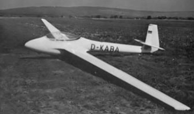
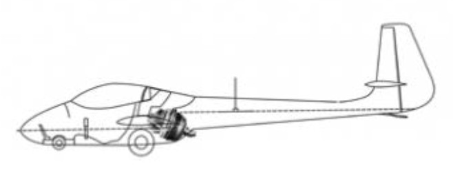
Hutter H30

Hütter 30 TS [Turbinensegler]

In 1954 Eugen Hänle was then Assistant Professor Ulrich Hütter in a company engaged in the manufacture of large wind turbines for electricity production. The design of the 17 meter blades used fiber reinforced plastic glass.

With this experience, Eugen Hänle, established Glasflügel in 1957, to produce helicopter rotor blades for Bölkow.

Meanwhile, he began with his wife Ursula, the construction of a 1946 Wolfgang Hütter H30 glider. The plans were followed, but replacing the plywood – balsa sandwich for all the shell (fuselage, wing, fin) by a balsa sandwich – laminate, and the first unidirectional fiberglass wing and epoxy resin spar .

The H-30, with a 13.60 m wingspan, was started in late 1957 and finished in 1960.

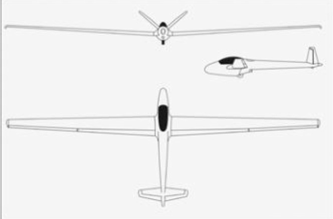
Meanwhile, Eugen Hütter had developed the H-30TS glider, derived from the H-30, with a modified fuselage to accommodate a small BMW turbojet and a new wing of 15 m with plastic flaps, but with glued aluminum sheet metal spar.

Hütter 30 TS [Turbinensegler]

The H30 TS was first fitted with a BMW 6011 (8025) turbojet of 36 kg thrust to 45,000 rev/min in September 1959. Then, in May 1961, following major modification, it was to be equipped with a BMW 6012 (8026) 40 Kp thrust to 46,000 rev / min .

Hütter 30 TS [Turbinensegler]

Due to problems with the turbine and especially the noise it produced, the project was stopped and the unit was re- turned as a pure glider. He was lost in August 1968 following an accident during a winch launch.

Hänle then used the molds to produce wings in the Schempp-Hirth workshop. Two sets of wings with glass fiber spar were made. One of the wings was the first H-301 libel, other than the first Swiss Diamond, with its original 15 m wingspan.

Gallery

Hütter 30 TS [Turbinensegler]
Engine: BMW 6011 (8025), 36 kg thrust to 45,000 rpm
Wingspan: 15.00 m / 49 ft 2.5 in
Length: 5.70 m / 18 ft 8.5 in
Height: 1.02 m / 3 ft 4.5 in
Max rate of climb: 150 m/min / 490 ft/min
Min sink: 0.60 m/sec / 1.97 ft/sec
Practical ceiling: 2500 m / 8200 ft

Hütter 30 TS [Turbinensegler]

Hutter H 17 / Goppinggen 5

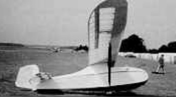
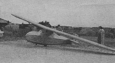
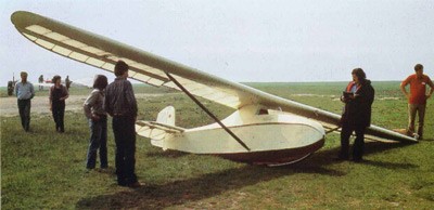
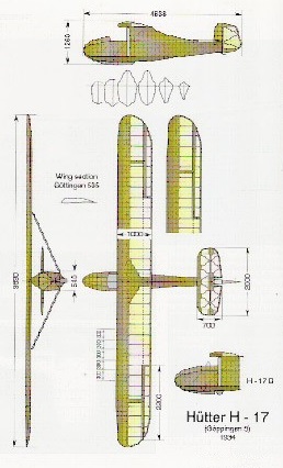
The H 17 was designed by the Hutter brothers, Ullrich and Wolgang, in Salzburg, Austria. The ‘17’ indicated the glide ratio. They sold plan sets until they joined Schempp-Hirth, which then built about five as the Goppingen 5 with the addition of a windshield and main wheel. Many were built from plans worldwide and several are still flying. A post-war version was developed and marketed as the H 17 B with enclosed cockpit, lengthened fuselage and airbrakes. The H 17B has slightly increased span and empty and loaded weights increased about 50%. One H 17 belongs to the National Soaring Museum. The Vintage Sailplane Association has plans.

1938

The structure was all wood, D-tube single-strut wing, plywood over simple frame fuselage, fabric cover.

Wing span: 9.69m /31.8ft
Wing area: 9.2sq.m /99sq.ft
Empty Weight: 65kg /143lb
Payload: 93kg /205lb
Gross Weight: 158kg /348lb
Wing Load: 17.2kg/sq.m / 3.52lb/sq.ft
Water Ballast: 0
L/DMax: 17 64 kph /35 kt / 40 mph
MinSink: 0.98 m/s / 3.2 fps / 1.90 kt
Aspect ratio: 10.2
Airfoil: root, Go 535 tip, NACA M-6
Seats: 1

Huth Kreis-Doppeldecker

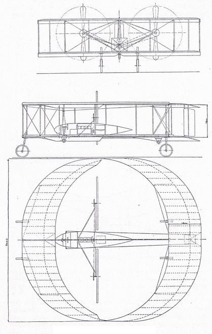
This biplane was designed by Dr. Fritz Huth and built at the Max Schüler Aeroplan-Fabrik (Berlin) in 1909. It had sickle-formed wings, the front pair with points to the rear and the rear pair with points forwards, so that almost ring-formed surfaces of 6 m diameter was formed. It’s reported that two were built, one by Huth’s Deutsche Flugwerft (Huth-Motor), another by Schüler (Aeolus-Motor).

Hurricane Co Hurricane Hauler

Designed for up to 300 lbs and 6.5 ft pilot. Strengthen undercarriage and 30% longer cockpit.

Speed max: 85 mph.
Cruise: 63 mph.
Range: 100 sm.
Stall: 35 mph.
ROC: 800 fpm.
Take-off dist: 200 ft.
Landing dist: 150 ft.
Service ceiling: 12,000 ft.
Engine: Rotax 503, 52 hp.
HP range: 40-65.
Fuel cap: 10 USG.
Weight empty: 600 lbs.
Height: 8.17 ft.
Length: 16.83 ft.
Wing span: 28 ft.
Wing area: 142 sq.ft.
Seats: 1.
Landing gear: nose wheel.

Hurricane Co Hurricane

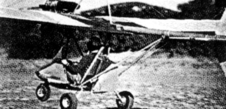
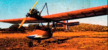
Hurricane 103

Circa 1995.
Suitable engines include the Rotax 447 to 582.
The Rotax 447 powered 103 ultralight kit was priced at US$8499 in 1997.
The Hurricane H.P./Clipwing has a symmetrical wing for mild aerobatics. Designed for +8 / -6 G, the kit price in 1997 was US$10,199.

Experimental
Engine: Rotax 503, 52 hp.
Wingspan: 28.5 ft.
Wing area: 142 sq.ft.
Length: 16.75 ft.
Height: 8.25 ft.
Seats: 1.
Empty wt: 280 lb.
Max wt: 680 lb.
Fuel cap: 10 USG.
Wing loading: 4.8 lb/sq.ft.
Pwr loading: 13.1 lb/hp.
Vne: 105mph.
Cruise: 70mph.
Stall: 30mph.
ROC: 1000 fpm.
TO dist: 100ft.
Ldg dist: 150 ft.
Endurance no res: 2.75 hr.
Range: 200 mile.
Fuel burn: 2.5 USG/Hr.

Ultralight
Engine: Rotax 447, 40 hp
HP range: 40-55
Wingspan: 28.5 ft.
Wing area: 142 sq.ft.
Length: 16.75 ft.
Height: 8.25 ft.
Seats: 1.
Empty wt: 250 lb.
Max wt: 500 lb.
Fuel cap: 5-7 USG.
Vne: 105mph.
Top speed: 100 mph
Cruies: 60 mph
Stall: 25 mph.
Range: 150 sm.
Takeoff distance: 100 ft
Landing distance: 120 ft
Service ceiling; 12,000 ft
ROC: 850 fpm.
Landing gear: nose wheel.

Hurricane H.P./Clipwing
Top speed: 105 mph
Cruise: 75 mph
Stall: 30 mph
Range: 130 sm
Rate of climb: 1000 fpm
Takeoff dist: 150 ft
Landing dist: 150 ft
Service ceiling: 12,500 ft
Engine: Rotax 503, 52 hp
HP range: 40-75
Fuel capacity: 7-10 USG
Empty weight: 275 lb
Gross weight: 650 lb
Height: 8.2 ft
Length: 17 ft
Wing span: 26-26 ft
Wing area: 133 sq.ft
Seats: 1
Landing gear: tailwheel

Hurlburt Hurricane / Camburn Special

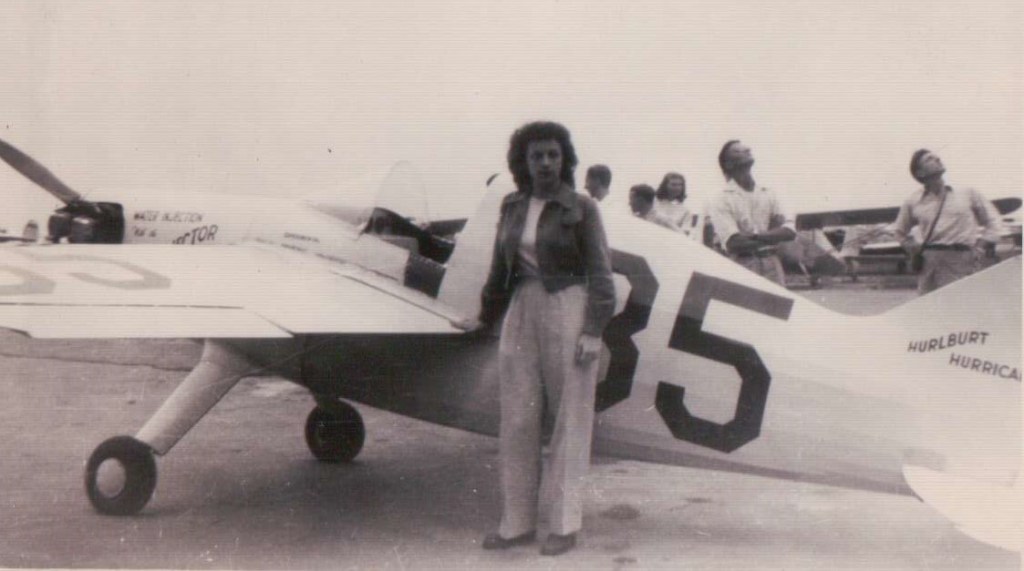
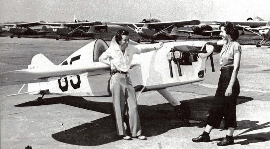
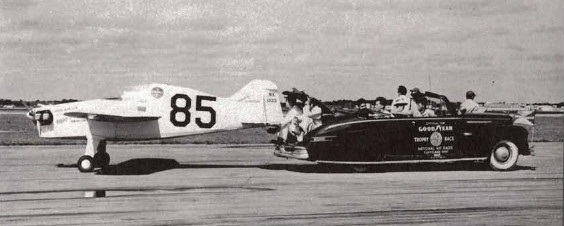
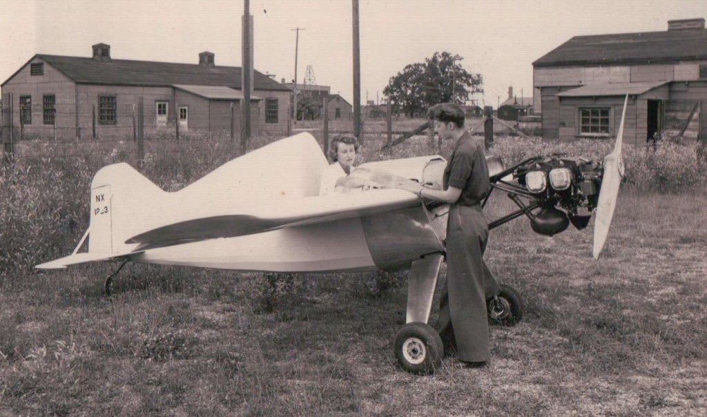
The Hurlburt Hurricane NX1223 of 1947 was designed and built by Marge Hurlburt, Anna Logan, and Duke Caldwell as midget racer #85.

Powered by an 85hp Continental C-85, the Hurricane was barred from Goodyear competition because the event was restricted to male pilots.

1947

Owned by Anna Logan and Mildred Caldwell of Cleveland, Eugene ‘Joe’ Smith flew the Hurricane in 1947.

The craft was later named the Camburn Special after Marge’s death. Eventually it was flown as Camburn Special in some competitions by Eugene “Joe” Smith.