France Developed a very extensive range of light aircraft, available for home construction from plans. These include MJ.2 Tempete single-seat wood/fabric aerobatic monoplane (first flown 1956), MJ.5 Sirocco tandem two-seat aerobatic monoplane (first flown 1962), MJ.8 as 75 percent scale replica of Fw 190 fighter, MJ.9 as 75 percent scale replica of Bf 109 fighter, MJ.10 Spitfire as 75 percent scale wooden replica of Supermarine fighter, MJ.12 as 75 percent scale replica of P-40 fighter, MJ.53 Autan side-by-side two-seater (first flown 1991), MJ.77 Gnatsum as 75 percent scale wooden replica of P-51 Mustang fighter, and a range of full-size replicas of Second World War fighters, including MJ.80/Fw-190, MJ.90/Bf- 109 and MJ.100/Spitfire.
1998: 2, allée des bordes F-94430 Cheneviére France
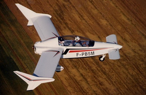
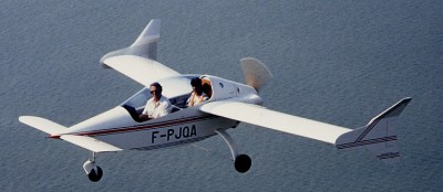
Developed from the RJ.02 Volucelle, the RJ.03 Ibis tandem two-seat canard monoplane, first flown 1991, was offered in plans form for home construction. In March 1992 the Ibis received its French certification at Pau airport in France. Totally enclosed in wood (spruce, douglas fir), it requires no fabric coverings. By utilizing a combination of “Styrodur” (polystyrene) with identically-matching plywood ribs and depression-bonding of surface-coatings, its surface finish matchs that of synthetic-fibre aircraft.
Fitted with “flaperons” on the wings, its approach speed is identical to that of classic aircraft bearing the same load per sq.m. With little nosing-up during approach, rearward and forward visibility is excellent. Due to the use of a nonlaminar surface on the canard, flights are not affected by rain.
The fuel consumption is only 13 l/h at 200 km cruising speed or 10 l/h at 180 km. The rate of climb is 700 fpmat max. take-off weight with only 60 hp.
The IBIS is designed to be used with different types of engines (VW-1830cc, VW-1915cc, French JPX-475T, Australian JABIRU 2200cc, Limbach-2000 EC) and can be fitted with certain types of rotary engines (MID-WEST). The structure comprises 7 frames, 4 longerons and diagonal struts. It is covered with plywood and requires no padding. The fuselage is assembled on the model plane principle, upside down on a table, and after construction of the different frames. The 150 pages handbook, included in the instruction document pack, will give you all the necessary explanations as regards: construction, adjustments and test flight techniques.
The canard wing is rectangular, with no twisting or dihedral angle. It has round tips which are bevelled on the underside. The trailing edge is fitted with a built-in slotted flap, which runs along the whole length of the wing. The canard structure consists of a “box-form spar” the same thickness as the profile and which joins 8 identical plywood former-ribs. The whole structure is filled with “Styrodur” foam, and covered with thin plywood which is glued by suction using the same technique as that employed in the construction of certain model planes. The wing spar is a “box-form” construction and consists of two caps braced together by means of plywood strips on each side. It is in one single piece, at an angle to the airframe. Width and height are constant along whole thickness of the profile. There is no dihedral angle or twisting. All wing ribs are identical, and are in plywood. They are made in a single operation using a metal template and a joiner’s spindle moulding machine. This can be done very quickly. The wing is filled with blocks of “styrodur” foam hollowed out to allow passage of flight control linkages and is covered with thin plywood glued by suction. This method represents a saving of circa 40% on the production time required for standard wood and fabric wing construction. The wing can be dismantled only for major overhaul. Each stabilizer consists of two half-stabilizers made of main plywood longerons and 5 plywood ribs. Thc stabilizers are completely filled with “styrodur”, and covered with glued plywood. The rudders are incorporated in the profile of the stabilizers. The cabin is heated. Internal luggage stowage is behind the passenger’s head. The one-piece canopy, opens laterally. The front undercarriage is mounted on a steering wheel, and is connected to the rudder dual controls; it is not retractable. It is made of steel tubes and fitted with a wheel mounted on a rocker, rubber shock absorbers with brakes on the rear-weels. The main undercarriage is made of glued laminated plywood, for weight, easy assembling and low cost. It is highly efficient even on grass runways. The dual flight control system is the “rigid linkage” type with ball, bell-crank levers and rod connecting joints. The steering and rudder controls are the only system making use of cables. Flight control of the plane is performed through: flaperons (flaps/ailerons) running the whole length of the main wing span, elevator on the canard wing, rudders on stabilizers. The IBIS is flown in a totally classic way. Fuel tanks are in epoxy resin and are incorporated in the leading edge of the wing. They have a capacity of 60 litres; they are equipped with a feed-tank and have a single refuelling point on the wing or on the luggage hold. The tanks are fitted with an electric fuel gauge and with a single pipe leading from the lower part of the feed-tank. There is no manual system for transferring fuel. The IBIS plane has been designed for use with VW (Volkswagen) engines in the 60 to 80 HP range, i.e. engines of at least 1830 CC or any more powerful VW engine. Any four stroke four cylinder engine, without reducing gear, weighing 75 kg or less, in good working order (and roughly equivalent to the VW or up to 20 kg lighter) presently in use or coming on line, can be mounted on the IBIS. It is also possible to use the French engine “JPX 4T 75A” 80 HP, the German “LIMBACH 2000 EC” 68 HP or Australian “JABIRU 2200” 80 HP. All of these engines are without a reduction gearbox. A two-stroke engine is not recommended as its specific consumption is much greater than that of the four-stroke engines. Some rotary engines can also be considered as alternative solutions. The 65 HP Continental engine is too heavy. Plans (set of 12 drawings and a 160 pages contruction handbook) of the IBIS aircraft are available in French and English version. Estimated construction time is put at 2200 hours. The IBIS RJ03 is classified in a “light aircraft category”. It cannot be modified as “ultra-light”.
Engine: VW Wing span: 6.3 m MAUW: 470 kg Empty weight: 260 kg Fuel capacity: 60 lt Max speed: 250 kph Cruise speed: 203 kph Minimum speed: 95 kph Climb rate: 3.5 m/s Seats: 2 Plan price (1998): 3000 F
Engine: VW, 60 hp. HP range: 60-80. Wing span: 6.30 m / 20.66 ft Length: 4.90 m / 16 ft. Height: 5.6 ft. Wing area: 52 sq.ft. Vertical stabilizer height: 1.76 m / 5.6 ft Fuselage width: 0.64 m / 26 in Cabin height: 1.04 m / 3.15 ft Cabin width at pilot elbow: 0.64 m / 26 in. Max. take-off weight: 470 kg / 1034 lbs Weight empty: 260 kg / 572 lbs. Fuel capacity: 60 lt / 16.2 US.G Payload (full fuel): 170 kg / 374 lbs Front pilot weight limits: 65-95 kg / 143-209 lb Vmo / Vne: 161 mph / 260 km/h / 140kts Normal cruise 65%: 200 km/h / 108 kt / 124 mph Long range cruise: 180 km/h / 97 kt / 112 mph Max. range: 900 km (485 nms) + VFR reserves – 559 sm Approach speed: 120 km/h / 65 kts / 74 mph Stall speed: 95 km/h / 52 kts / 59 mph ROC: 650 fpm. Vz: 3.5 m/s Takeoff distance: 1050 ft Landing distance: 1500 ft G-loading: +4.5 and -3.0 Seats: 2 tandem. Landing gear: nose wheel.
Engine: VW 1835 cc Wing span: 6.30 m / 20.66 ft Length: 4.90 m / 16 ft. Height: 5.6 ft. Wing area: 52 sq.ft. Vertical stabilizer height: 1.76 m / 5.6 ft Fuselage width: 0.64 m / 26 in Cabin height: 1.04 m / 3.15 ft Cabin width at pilot elbow: 0.64 m / 26 in. Climb rate: 700 fpm at M.T.O. weight. Fuel capacity: 60 lt / 16.2 US.G
In 1987, Roger Junqua and his son Jean-Claude presented a small, all-wood two seater canard at the International Amateurs Builders air show in Brienne-le-Chateau in France. The “VOLUCELLE”, as it was called, with its futurist lines, after testing, turned out to be an excellent airplane. However, it remained a prototype which was used as a research and test-bed airplane for the development of the “IBIS”.
John M. Larsen immigrated to the U.S. in 1892 from Denmark. As an engineer he designed, produced and sold cooling machines in the U.S.A. In 1919 he intended to sell U.S. aircraft in Denmark, but during his stay in Europe he also saw the Junkers F13 and was interested in selling the Junkers F13 within the USA. Together with Junkers he founded the Junkers Larsen Corporation in 1920, which was responsible for the marketing of Junkers aircraft in the USA. Larsen managed to sell some of the modified F13 as JL6 to the U.S. Army and to the U.S. Postal Office. But due to a series of crashes the JL6 was grounded by both. Larsen also converted one JL6 to a war machine as JL12, but the U.S. Army was not interested in this aircraft and the joint venture was stopped after a few sales, in 1920.
Besides Bachem with the Ba-349 Natter, three other companies submitted proposals for the Jägernotprogramm (Emergency Fighter Program). The front runner was Ernst Heinkel A.G. with their P.1077 Julia which took off from a rail and landed on a skid like the Me-163, the runner up was the Junkers Flugzeug und Motorenwerke’s EF-127 Walli; the Messerschmitt A.G.’s P.1104 was also in the running. As expected, Heinkel won the contract.
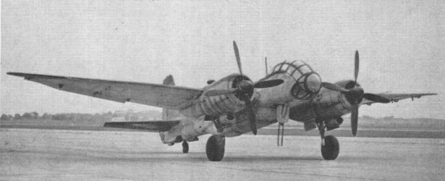
Some sources claim that this was a development of the Ju 388, but it actually was a four-engined long-range bomber, built of Ju 188, Ju 288 and Ju 388 parts. The development of the Ju 488 was ordered from manufacturers in occupied France, who were not very motivated. When the prototype finally neared completion in 1944, it was destroyed by the French resistance with sten guns and grenades.
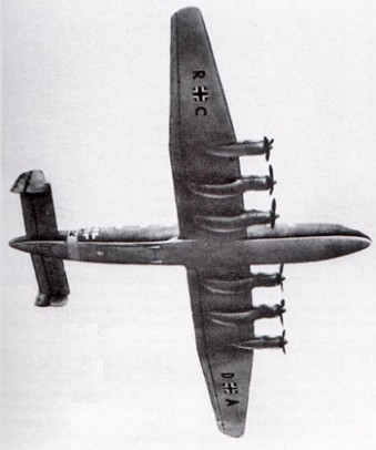
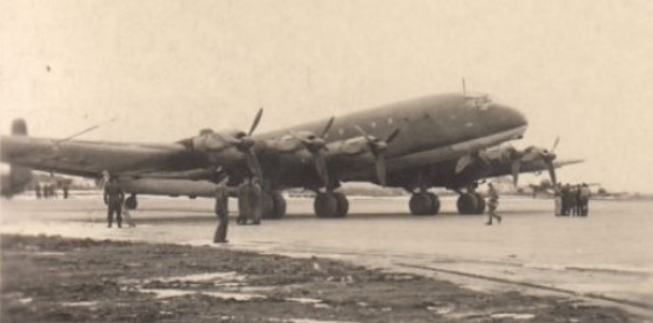
The German Junkers Ju 390 long range heavy bomber aircraft design was intended to be able to strike at locations along the east coast of the United States during World War 2. The Ju 390 itself was a further development of the Junkers Ju 290 and was also tasked to fulfill the roles of maritime reconnaissance and transport in addition to its bombing duties. The Ju 390 – also known under the unofficial name of “New York Bomber” – was developed as two working prototypes, effectively making the idea of transatlantic bombing theoretically possible for Hitler and his Luftwaffe. The Ju 390 was part of the failed “Amerika Bomber” project considered by the Germans, this including the Messerschmitt Me 264 and Focke-Wulf Ta 400 designs.
The Junkers Ju 390 heavy bomber appeared when general German wartime philosophy was still centered around medium-class bomber aircraft. Full developmental resources were never really delegated to the Ju 390 project en mass and the entire program was slow. With origins in the Ju 290 airframe, the Ju 390 basically saw its wings lengthened via extensions fitted to help accommodate the additional engines (three to a wing for a total of six installations). The fuselage was also applicably lengthened for the long-range bombing role. Defense was supplied by a pair of 13mm machine guns in a gondola position as well as 2 x 13mm machine guns in beam positions. A pair of 20mm cannons would have been mounted to a dorsal turret and a single 20mm cannon would have been installed in the tail. Crew accommodations would have amounted to ten personnel made up of the flight crew and dedicated gunners. The heavy transport model was given the proposed designation of Ju 390A-1 while the maritime patrol and long-range heavy bombers would have been assigned Ju 390B and Ju 390C respectively.
Ju.390 V-1 GH+UK
Power for the Ju 390 V01 prototype was supplied by 6 x BMW 801D radial piston engines, of 1,730 hp. Maximum speed was listed at 314 miles per hour with a range of approximately 6,030 miles. The service ceiling was a reported 19,700 feet. Empty weight was in the vicinity of 87,100lbs while maximum take-off weight topped at 166,400lbs. The Ju 390 maintained a length of 112 feet, 2 inches with a span of 165 feet, 1 inch. Her height was 22 feet, 7 inches.
First flight for a Ju 390 V1 prototype occurred on October 20, 1943, and Ju 390 V2 was also flown in October of 1943 with testing believed having gone into 1945.
An initial order of 26 Ju 390s were ordered for serial production, however, the program was cancelled in June of 1944 to allocate critical wartime resources and development to other more pressing projects. Pparticularly those of defensive in nature. The Ju 390 was officially strickened from Luftwaffe contention in 1945. Ju 390 V1 was destroyed on the ground by the Germans as the American Army closed in on the development facility.
A test flight of a Ju 390 is said to have taken the aircraft from Brest, France, to within 200 miles of New York city, and returned.
In the fall of 1944, Japanese authorities were granted local production rights to the Ju 390, though none were ever started before the Empire capitulated in August of 1945.
Junkers Ju 390 V1 (New York Bomber) Engines: 6 x BMW 801D radial, 1268kW. Length: 112.20ft (34.2m) Width: 165.03ft (50.30m) Height: 22.60ft (6.89m) Empty Weight: 87,083lbs (39,500kg) Maximum Take-Off Weight: 166,449lbs (75,500kg) Maximum Speed: 314mph (505kmh; 273kts) Maximum Range: 6,027miles (9,700km) Service Ceiling: 19,685ft (6,000m) Armament proposed: 2 x 13mm MG 131 machine gun in gondola 2 x 13mm MG 131 machine guns in waist beam positions. 2 x 20mm MG 151/20 cannons in dorsal turret 1 x 20mm MG 151/20 cannon in tail gun position Crew: 10
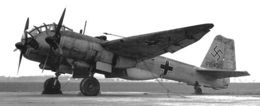
The Junkers Ju 388 was a 1944 development of the Junkers Ju 188. There were three versions, J (hunter), K (bomber) and L (reconnaissance aircraft). The first prototype, the Ju 388 L-0 V 7 with the factory serial number 300,001, PG+YA, developed using of major components of the Ju 188 and flew for the first time in December 1943. The prototypes built were V 1 to V 6 (2 each of the J-1, K-1 and L-1) during 1944. Structural areas and the horizontal tail unit of all versions were taken completely from the Ju 188, the chassis from the Ju 88. In contrast to the Ju 188 the Ju 388 possessed a pressurized cabin for three man crew. In order to improve the aerodynamics and speed, the portion of the cockpit were omitted but a remote controlled tail FHL 131 Z was inserted. The wings were defrosted as with the Ju 188 by warm air by the engines, the snow and ice removal of the horizontal stabilizers took place via a gasoline Kaercher furnace. The only version of this Ju 188 development to enter production before the end of the war was the Ju 388L reconnaissance aircraft, a small number of which were built. Power was provided by two 1,349kW BMW 801TJ engines.
One Ju 388 L-1, 560,049 was captured by the Americans in the Merseburg works. It originated from production from Weser flight in Liegnitz/Schlesien, and parts were manufactured by ATG. It was brought with other German airplanes on the aircraft carrier HMS Reaper in Operation Sea Horse for tests into the USA. These took place in Wright Field, Ohio. The machine carried the identification FE-4010 (later T2-4010).
In 1947 the tests finished, and 560,049 / FE-4010 found its way to the National Air & Space Museum. Unrestored, the cockpit of the Ju is 388 L is nearly in the original state.
Engines: 2 x Junkers Jumo 222E Wingspan 22 m (72 ft. 2.125 in.) Length 14.95 m (49 ft. 1 in.) Height 4.9m (16 ft 1 in) Weight 10,565 kg (23,296 lb.) empty Top speed: 414 mph @ 37,700 ft. Range: 1100 miles Ceiling: 42,200 ft Armament: 3 x 13mm mg
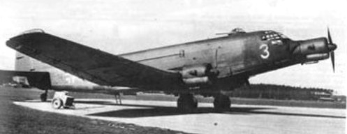
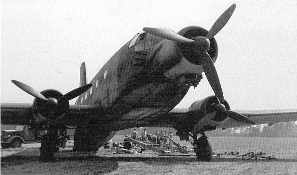
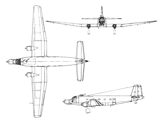
The Ju 352 development was based on wood in order not to use strategic materials. Power was provided by three 894kW Bramo 323R-2 engines. Production of this version totalled 43 or 44.
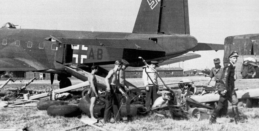
Ju 352 T9+AB at Juvincourt unloading AR234 equipment – Erich Sommer at right
One of the features of the Ju 352 was its Trapoklappe hydraulically-operated loading ramp. Incorporating its own central stairway, this ramp, when lowered, raised the aircraft to a near horizontal position which facilitated easy loading and unloading. Another feature were its reversible pitch propellers.
T9+AB
A total of ten pre-production Ju 352 A-0s and 33 A-1 production aircraft were completed before construction was halted in September 1944.
A number of Ju 352 were delivered to Versuchsverband including T9+AB, T9+MB and T9+AL.
A 1941 flying-wing transport glider, built in competition with the Me 321. The RLM insisted that the Ju 322 would be built of wood, a construction technique not used by Junkers since 1918. Junkers employed a wing like that of the G 38 on a transport glider design, the Ju 322 Mammut (Mammoth) but stability problems showed up on its first test flight.
The RLM had ordered 200, but the Ju 322 was cancelled after the prototype proved unstable. The Me 321 was selected for production.
The 62 m (203 ft) span glider was towed by a Ju 90 towplane (for whose take off 5 km (3 miles) of forest had been cleared from the end of the Junkers airfield at Mersburg) and had to be cast off. It landed in a meadow where it lay for two weeks before it was towed back to the airfield by the two tanks it had been designed to carry. Both it and 99 other Mammuts under construction were sawn up into firewood.