Kolb Firefly

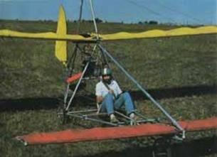
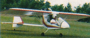
Designed by Homer Kolb, the Firefly was designed to be a legal ultralight with the twin cylinder 40HP Rotax 447 engine installed.
This single seat LSA Firefly features 10 minute wing folding and a Quick-build option. The Quick-buid option represents approximately 50% of the building / assembling time of the aircraft.

Engine: Rotax 447, 41 hp.
Wing span: 22 ft.
Wing area: 117 sq.ft.
Height: 5.83 ft.
Length: 19.5 ft.
Empty weight: 252 lbs
Gross weight: 500 lbs
Fuel tank: 5 USgal.
Speed max: 70 mph.
Cruise speed: 60-65 mph
Stall speed: 30 mph
Climb rate: 1,000 fpm
Take-off roll: 150 ft.
Landing dist: 150 ft.
Cockpit width: 22 in
Landing gear: tail wheel.
Seats: 1.

Kondor D-7

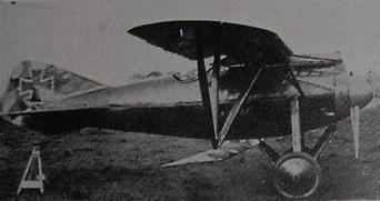
The Kondor Dreidekker, first flown in October 1917, was not a success. Instead, Kondor used the fuselage, empennage and lower wing of the Dreidekker to produce over the winter of 1917-18 a biplane or sesquiplane called the D.7 designed by Walter Rethel.

The common fuselage was a tube steel internal structure with plywood skin, rounded in cross-section. At the front the fuselage reduced smoothly in diameter to a large spinner with a two blade propeller driven by a 160 hp (120 kW) six-cylinder, liquid-cooled upright inline Mercedes D.III engine, though there are hints in the records suggesting an earlier, different engine. The upper part of the engine protruded above the fuselage, enclosed in its own cowling. At the rear the tailplane was mounted at mid-fuselage under a long chord fin with a strongly swept leading edge, carrying a deep rudder. There was a shallow ventral fin. The D.7 had a fixed conventional undercarriage, with each mainwheel’s leg placed vertically and mounted at mid-fuselage, assisted by a forward leaning strut attached under the nose. A long tailskid reached rearwards from the forward edge of the ventral fin.

The wings of the D.7 had constant chord and the upper one was supported just above the fuselage on a cabane. The cockpit was aft of its trailing edge, where there was a central rounded cut-out to assist the pilot’s upward and forward view. The lower wing, narrower in chord, was not directly attached to the fuselage but supported centrally by rear leaning struts from the undercarriage structure. The interplane struts were also unusual; three struts were attached at the same point on the lower wing, spreading out upwards into an inverted tripod or pair of Vs.

The date of the D.7’s first flight is not known though it must have been after October 1917, when the Dreidekker was flying, and before May 1918 when a report from the Idflieg said the D.7 was about to recommence testing with the Mercedes engine. It was not entered into the second D-type (fighter) competition of June 1918, suggesting Kondor were beginning to concentrate on the monoplane designs suggested by the success of the Fokker D.VIII, a process that led to the Kondor E.III.

The D.7 remained a prototype and its development was soon abandoned.

Engine: 1 × Mercedes D.III, 120 kW (160 hp)
Propeller: 2-blade
Wingspan: 8.50 m (27 ft 11 in)
Wing area: 15.70 m2 (169.0 sq ft)
Length: 6.20 m (20 ft 4 in)
Height: 2.30 m (7 ft 7 in)
Empty weight: 590 kg (1,301 lb)
Gross weight: 785 kg (1,731 lb)
Maximum speed: 180 km/h (112 mph; 97 kn)
Endurance: 1.45 hr
Crew: One

Kondor Dreidekker

In the summer of 1917 Kondor followed the lead of Fokker’s Dr.I July 1917 triplane with one of their own. Known only as the Kondor Dreidekker this aircraft, first flown in October 1917, was not a success; its development programme was soon abandoned because of severe vibrational problems. Instead, Kondor used the fuselage, empennage and lower wing of the Dreidekker to produce a biplane or sesquiplane called the D.7.
The common fuselage was a tube steel internal structure with plywood skin, rounded in cross-section.

Konchus Antis

The Lithuania Konchus Antis is a single-seat monoplane with cable braced wing plus canard. 25 hp pusher engine. Tricycle landing gear. Length 20’, wing span 31.3’, wing area 170 sq/ft. with canard. Empty weight 220 lbs. Gross weight 400 lbs. Top speed 38 mph and stall speed 26 mph. Wing and tail structure from tubing and fabric. Fuselage is tubing.

Komta Komta

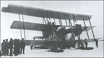
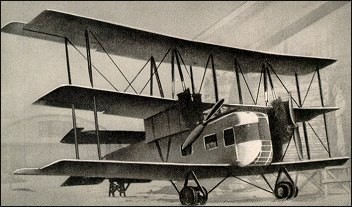
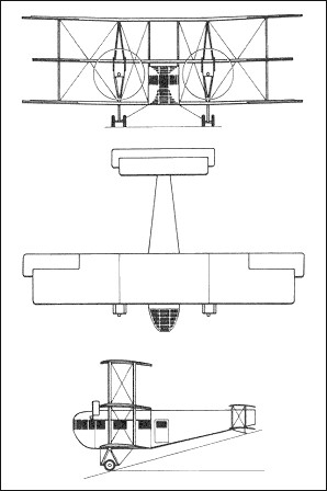
The Komta was not only the name of the aeroplane but also the name of the organisation set up to build it in the first place, under the chairmanship of Zhukovskii he of the ANT, Central Aero and Hydronamic Institute. The name comes from the “KOMissia po Tiazholot Aviatsii or the Commission for a Heavy Aircraft. The plane did not take to the air until late 1923 and by 1924 it had just about had it with the engines worn out. By this time Zhukovskii’s protogee, A.N.Tupolev, had taken over the design of large aircraft at the institute and so the Komta was no more.

Kollman Raptor

A copy of the Fledge with a composite airframe the same platform as a Fledge. The airfoil was a 2412. It is nearly symetrical with a low pitching moment. The first step was to make the D-tube and load test it. The first D-tube weighed 25 lbs. Jim Marske gave the info and the D-tube was successfully loaded to +7 g’s -4g’s.

The original rigid wing design was scrapped. A new design was started named the Raptor. The Raptor would use the same pitch stable airfoil that’s on the Marske Monarch. A new set of D-tubes were completed. These were made of foam and fiberglass with a carbon fiber spar. They weighed 25 lbs each and were load tested to verify the strength.

While waiting for the sail it was decided to build a hard wing version of the Raptor. Using Marske Monarch molds for the D-tubes, the D-tubes were made to Monarch specs with the addition of some twist. The D-tubes weighed 32 lbs apiece. Since they were built to Monarch strength they were stronger than necessary for a hang glider. The ribs were made of fiberglass and spruce. There was also a spruce trailing edge. The airframe was covered with heat shrinkable Mylar. The empty weight was 140 lbs.

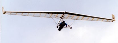
The wing was essentially a Monarch wing swept back with tip rudders. It has a standard control bar with struts and no top rigging. The pilot uses weight shift for pitch. For roll control sliders are used just like on the later Fledge hang gliders.

The plan was to aerotow the Raptor and make short hops and feel it out. The first flights were made in spring of 1994. Ten feet of altitude resulted in a long flat glide. The drag rudders were responsive and predictable. After many hops with the highest being 100′ it was decided to tow to 5000′ and feel it out. The climb up to 5000′ was uneventful. After release the first thing to find out pitch stability. Pulling on the bar, the bar pressure built up steadily. There was very little bar movement but substantial bar pressure. Below 15 mph indicated it felt mushy but wouldn’t break or fall off to one side. The glider never stalled and broke it just goes into a low speed mush with a high sink rate. Direction control is still there because the drag rudders are still working. The slider controls worked well but it was clear I didn’t have enough mechanical advantage on the rudders. When the glider was banked it would tend to tighten up and turn higher unless high side rudder was used. All in all it was a sucessful flight. The Raptor felt stable and controlable. The handling wasn’t great but it was acceptable for a first flight. The Raptor prototype weighed 140 lb.

After a couple months reworking the rudder cables and playing with different dihedral settings the handling got just right. The Raptor was now roll neutral. That means it stays banked at what ever angle it is set at. Deploying a rudder makes the glider roll in that direction. Once the desired bank angle is achieved the rudder is released. The Raptor will continue to turn at that bank angle. To return to level flight the opposite rudder is applied. This was just like weight shifting.

One of the first thing noticed was the Raptor’s ability to turn tight and climb in thermals.

It was decided to set up a production run of three gliders and 6 D-tubes and hardware needed wasn’t available off the shelf. Others wanted collapsible gliders and they wanted smaller gliders. The collapsible was a challenge. The first collapsible glider took almost an hour to put together and it wasn’t easy. It also weighed over 130lbs. To get the smaller size wing and still use the same molds the airfoil was modified. Truck tested the pitch curves were well in excess of what the H.G.M.A. required. By changing the size and modifying the aerfoil the dihedral setting was going to need change. This wing was a lot more sensitive to dihedral settings. The sink rate seemed similar but the glide was definitely better than other hang gliders. This wing isn’t able to generate lift as well at lower speeds.

Through repeated set ups and break downs and modifying the design, at 105 lbs. it set up faster and easier. The sail was made by Dick Cheney. Using the original airfoil with less area than the first prototype, this glider flew great from the first flight. The performance seemed even better than the first glider. The only negative to report is bar pressure. Flying above 45 mph is very difficult because of too much bar pressure.

There was a total of 2 hardwings and 5 collapsible gliders built to September 1999. All of the gliders were load tested and passed. The different D-tubes were all constructed using different techniques and the lightest one was 19 lbs.

The next redesigned was 15 lbs lighter and with the 20 lb D-tubes for a weight of 75lbs. The amount of twist was reduced by 2 degrees, and the also reflex reduced on the airfoil to lessen bar pressure.

The Raptor is now flown by weight shift. The wing is built to cantilever strength with a shifting control bar that is connect to the the rudders. When you shift your weight the control bar shifts deploying the rudders. This is the same system used on other rigid wings except thier cables are connected to spoilers. The beauty of this system is a hang glider pilot gets on it and it flies just like a weight shift glider.

The Raptor 2 appeared in 1994.

Raptor
Wing area: 15.04 m²
Wing span: 12.49 m
Aspect ratio: 10.5
Hang glider weight: 34 kg
Minimum pilot weight: 59 kg
Maximum pilot weight: 112 kg
Max glide ratio (L/H): 18
Max glide ratio speed: 56 km/h

Raptor 2
Max glide ratio (L/H): 18
Kolbanyi I

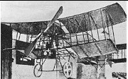
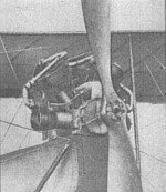
The 1910 Kolbanyi I biplane was designed and built by Geza Kolbanyi in Hungary, who together with Sylvester Golcsek designed and built an innovative 6 cylinder engine producing 60 HP and weighing only 230 lb.

It took to the air, but crashed due to the inexperienced pilot

Span: 33’5″
Length: 26’3″
Take-off Weight: 880 lb

Kokusai Ki-76 / Nippon Ki-76

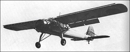
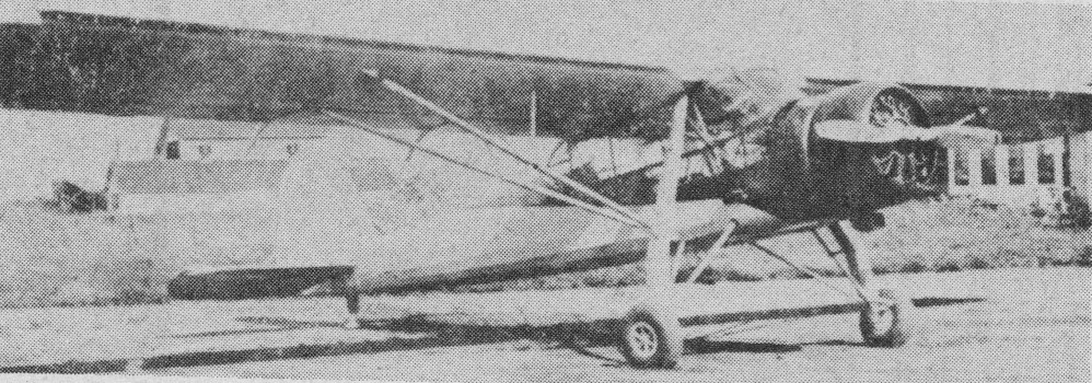
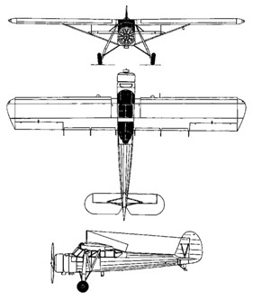
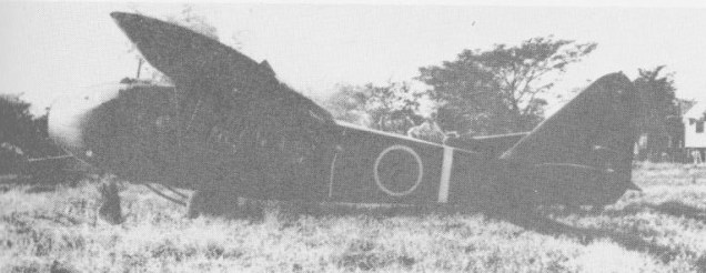
In 1940, the Imperial Japanese Army Air Force ordered the Nippon Kokusai Koku Kogyo to produce an artillery spotting and liaison aircraft. The resulting Ki-76, or Liaison Aircraft Type 3 (in Japanese: 三式指揮連絡機), was inspired by, and similar to, the German Fieseler Fi 156 “Storch”, although not a direct copy. A high-winged monoplane with a fixed tailwheel undercarriage, the Ki-76 used Fowler flaps, and was powered by Hitachi Ha-42 radial engine.

First flying in May 1941, the Ki-76 proved successful when evaluated against an example of the Fi-156, and was ordered into production as the Army Type 3 Command Liaison Plane in November 1942. 937 including a single prototype were built.

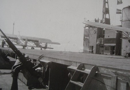
The Ki-76 remained in service as an artillery spotter and liaison aircraft until the end of the war. Ki-76s were also used as anti-submarine aircraft, operating from the Japanese Army’s escort carrier, the Akitsu Maru, being fitted with an arrestor hook and carrying two 60 kg (132 lb) depth charges.

Kokusai Ki-76 spotter planes on deck of Imperial Japanese Army landing vehicle carrier Akitsu Maru

The Allied reporting name was “Stella”.

Some were used by the Royal Thai Air Force.

Ki-76
Engine: 1 × Hitachi Ha42, 231 kW (310 hp)
Propeller: 2-bladed fixed-pitch
Wingspan: 15 m (49 ft 3 in)
Wing area: 29.4 m2 (316 sq ft)
Length: 9.65 m (31 ft 8 in)
Height: 2.9 m (9 ft 6 in)
Empty weight: 1,110 kg (2,447 lb)
Gross weight: 1,530 kg (3,373 lb)
Max takeoff weight: 1,623 kg (3,578 lb)
Maximum speed: 178 km/h (111 mph, 96 kn) at sea level
Range: 750 km (470 mi, 400 nmi)
Service ceiling: 5,630 m (18,470 ft)
Guns: 1× 7.7 mm (0.303 in) machine gun in rear cockpit
Bombs: 2× 60 kg (132 lb) depth charges (some variants)
Crew: 2

Kokusai Ku-8

Near the end of 1941 one Ki-59 was modified into a glider with the removal of the engines and the landing gear replaced by under-fuselage skids. It was designated the Ku-8-I or Army Experimental Glider. This was further developed as the Ku-8-II or Army Type 4 Large Transport Glider which became the only operationally-used Japanese assault glider. It was named ‘Goose’ by the Allies but subsequently changed to ‘Gander’.

Carrying a crew of two and 15-20 armed troops, the Ku-8 jettisoned its main undercarriage after take-off, landing on fixed under-fuselage skids. The tail wheel was also fixed. Small vehicles or artillery pieces, when carried, were loaded from the front, the whole nose section hinging to starboard. Troop entry was via the outward opening door in the fuselage side.

Variants:

Ku-8-I (Army Experimental Glider)
Experimental conversion to glider configuration.

Ku-8-II (Army Type 4 Large Transport Glider) (“Gander”)
Assault-glider variant.

Span: 75 ft 0 in
Crew: 2
Payload: 15-20 troops