Formerly known as the KB-17, this Yugoslav two seater high performance trainer was designed and built by the Letalski Institut Branko Ivanus, Slovenija – LIBIS at Ljubljana.
Of largely wooden construction, with a fabric covered welded steel tube fuselage, the LIBIS-17 has a cantilever single-spar high-set wooden wing, with a plywood covered leading edge torsion box supported by Styrofoam, the remainder of the wing being fabric covered. The fabric covered wooden Frise ailerons are also filled with Styrofoam, and there are Hiittertype wooden plate spoilers in the wing upper surfaces immediately aft of the spar. The angular tail unit is also a wooden structure filled with Styrofoam, and is made up of an all-moving one-piece fin and tailplane, each with a servo tab. The landing gear consists of a non-retractable unsprung Borovo main wheel and nose sheel in tandem, with a LIBIS mechanical brake. The two pilots are seated in tandem under a forward-hinged one-piece blown canopy; a ventilation system is provided and blind flying instrumentation, radio and oxygen equipment can be fitted if required.
It is cleared for looping, spinning and cloud flying as well as normal flight; it is also suitable for flying solo up to the Silver and Gold C standards.
The prototype LIBIS-17 first flew on October 1961, and the first production aircraft flew in June 1963; by 1972 there were 23 examples of the type on the Yugoslav civil register.
Span: 55 ft 9 in Length: 25 ft 1 in Height: 8 ft 11.5 in Wing area: 237.9 sqft Aspect ratio: 13.0 Empty weight: 739 lb Max weight: 1,135 lb Max speed: 138 mph (in smooth air) Max aero-tow speed: 87 mph Min sinking speed: 2.82 ft/sec at 47 mph Best glide ratio: 27:1 at 58 mph
The LIBIS KB-11 Branko was a 1950s Yugoslavian four-seat monoplane. The aircraft design office of the Letalski Institut Branko Ivanus Slovenija brought together teachers and students of the Ljubljana technical high school for the KB-11 Branko.
The KB-11 Branko was a development of the earlier two-seat KB-6 Matajur. First flown in December 1959 the KB-11 was an all-metal cantilever low-wing monoplane with retractable tricycle landing gear and an enclosed heated and ventilated cockpit for four persons. Intended for use as an air-taxi our business use but only small numbers were built.
Engine: 1 × Lycoming O-435-1, 138 kW (185 hp) Wingspan: 10.59 m (34 ft 9 in) Length: 8.23 m (27 ft 0 in) Height: 2.45 m (8 ft 0 in) Wing area: 1.152 sq.m (12.40 sq ft) Aspect ratio: 7.76:1 Airfoil: NACA 3415 at root, USA 35B at tip Empty weight: 800 kg (1,764 lb) Gross weight: 1,250 kg (2,756 lb) normal loaded without tip tanks Maximum speed: 214 km/h; 116 kn (133 mph) at sea level Cruise speed: 171 km/h; 92 kn (106 mph) at 1,525 m (5,000 ft) and 75% power Stall speed: 98 km/h; 53 kn (61 mph) Range: 950 km (590 mi; 513 nmi) Service ceiling: 5,334 m (17,500 ft) Rate of climb: 4.3 m/s (850 ft/min) Crew: 1 Capacity: 4 total
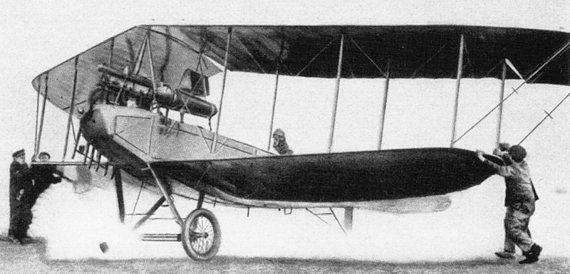
A swept wing, single engine, two seat biplane built in 1914 by the Luft-Fahrzeug-Gesellschaft in Reinickendorf (Berlin). Before the outbreak of World War I Bernard Langer flew the machine shown, equipped with a 100 hp Mercedes D.I engine and an extra tank above the fuselage in place of the passenger, on a non-stop sixteen hour flight. During WW1 at least one Pfeilflieger served with the Schutztruppe (Protection Force) in German South West Africa, now Namibia, between 1914 and 1915.
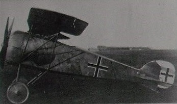
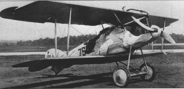
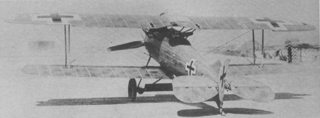
Late D.VIb tested at McCook Field post-war. Engine cowling removed for cooling
Late in 1917 the prototype D.VI appeared. The D VI followed the D II series and was built for the January 1918 German fighter competition. Two versions, one with a 160 hp water cooled Mercedes DIII engine and another with an improved 180 hp Mercedes, were entered in the fighter design competition of January 1918. There they lost to the Fokker that was to become the D.VII.
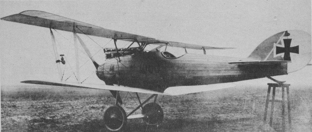
Prototype with original tail configuration and 160-hp Mercedes engine
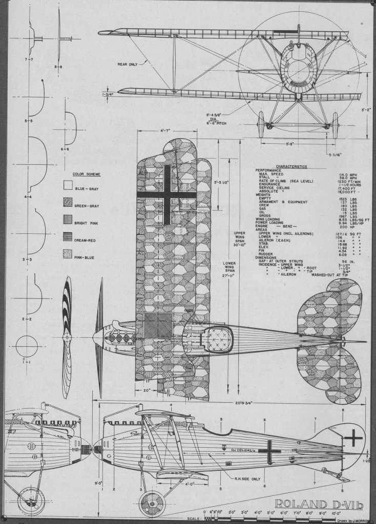
There was little to distinguish the standard production D.VIa from the earlier D.VIb other than the designation lettering on the side of the fuselage and the visible details of the different engines. Early models in each series had the radiator filler cap on the centre line of the upper wing while later models had it at the right side of the radiator. Late V.VI’s and all production S.VIb’s had a diagonal brace wire running from the lower rear wing strut to the upper wing overhang. Late model D.VIb’s were mostly identified by the installation on wider elevators which had aerodynamic balance areas extending forward to the hinge line. Serial numbers were not accurate because many D.VIb’s had earlier serials than late D.VIa’s.
Late D.VIa 5012/18
The D.VI wings were built up of wood spars and ribs, fabric covered. While the stabiliser was wood and fabric, the vertical fin on all but a few of the experimental prototypes was plywood covered. A unique feature was the fuselage construction. Roland used longitudinal strips of solid wood tapered to conform to the fuselage lines and planed to a wedge-shaped cross section to allow overlapping of adjacent strips exactly like shiplap in a “clinker-built” boat. This was officially termed “Klinkerkonstruction” and was exclusive with Roland.
Centre section bracing consisted of two welded steel tube assemblies instead of individual struts; outer wing struts were wood. Landing gear struts were streamlined steel tubing cross-braced with wire. The axle, secured to the landing gear struts with rubber shock cord, was carried inside a streamlined spreader bar fairing hinged at its top to allow upward movement of the axle when under load. The lower wing was not attached to the bottom of the fuselage but mounted on a narrow external keel that projected below the fuselage proper. The rear landing gear struts also attached to this keel where it joined the rear wing spars.
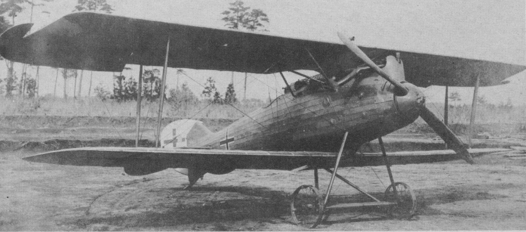
D.VIb – one of thirteen taken to USA
Installation of the radiator in a flat position in the centre section of the upper wing was standard practise. This type of installation was adequate in northern an central Europe but postwar tests of a C.VIb at McCook Field, Dayton, Ohio, revealed the cooling inadequate under American climatic conditions.
The aileron control system was adapted from that of the French Nieuport 11 and 17 in that a steel torque tube projected from the hinge line of the aileron to the centre section over the cockpit. Cables from control horns on the tube connected directly to a rocking beam under the control stick. The D.VI was the first German fighter to feature a horizontal stabiliser that could be adjusted for in-flight trim. The entire stabiliser pivoted about the rear spar. Other fighters with trim control had bungee springs or set screws attached to the stick.
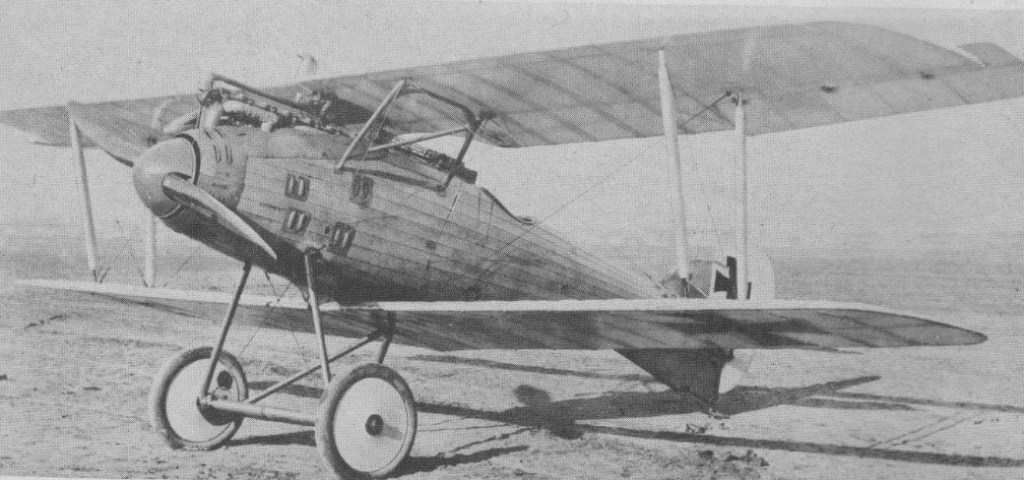
Early production D.VIb 2216/18 shows unbalanced elevators common to all A’s and early B’s.
Later evaluation resulted in production orders for two improved Rolands, the D.VIa with the 180 hp Mercedes and the D.VIb with a new model 185-200 hp Benz, another six cylinder. Both of these engines had been tested in experimental D.VI, which were themselves undergoing considerable aerodynamic refinement, and no special designations were applied to identify the various prototypes by powerplant or other feature.
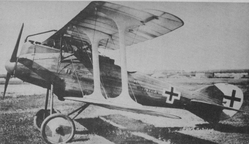
Experimental modification of early D.VIb 2217/18 with double-bay wings and I-struts
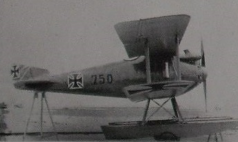
The Roland D.VI reached the front in service quantities shortly after the Fokker D.7. A few D VIs were used over the Western Front, while others went to the German navy for the defence of seaplane bases.
D.VI with original 160-hp Mercedes, vertical tail has added balance area. Balanced ailerons also installed.