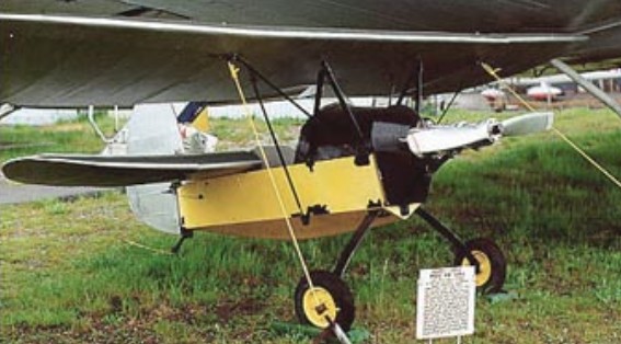
Mijelson-Morschikhin U-4

The MU-4 (Russian: Михельсон/Никитин МУ-4) amphibious flying boat was designed and built by NG Mijelson at Leningrad Factory No.23. The initials MU correspond to Morskaya Uchebnaya or Marine Trainer.

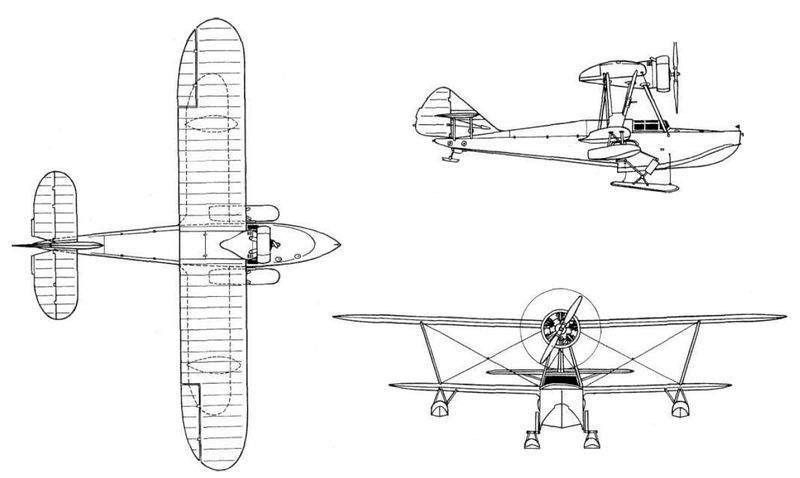
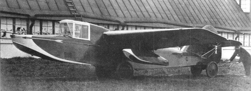
The MU-4 was designed as a flying-boat with a single hull and amphibious capacity. The hull was made entirely of wood and was made up of five watertight departments.

The wing configuration was sesquiplanar with the wing box braced by V-shaped struts made of duralumin. The wooden wing featured a double spar structure with a slim profile and constant chord. The covering was fabric. The lower plane was inserted into the fuselage, while the upper one was located high above the cabin, from where the engine supports started. The drop-shaped stabilization floats were located in the lower wing.

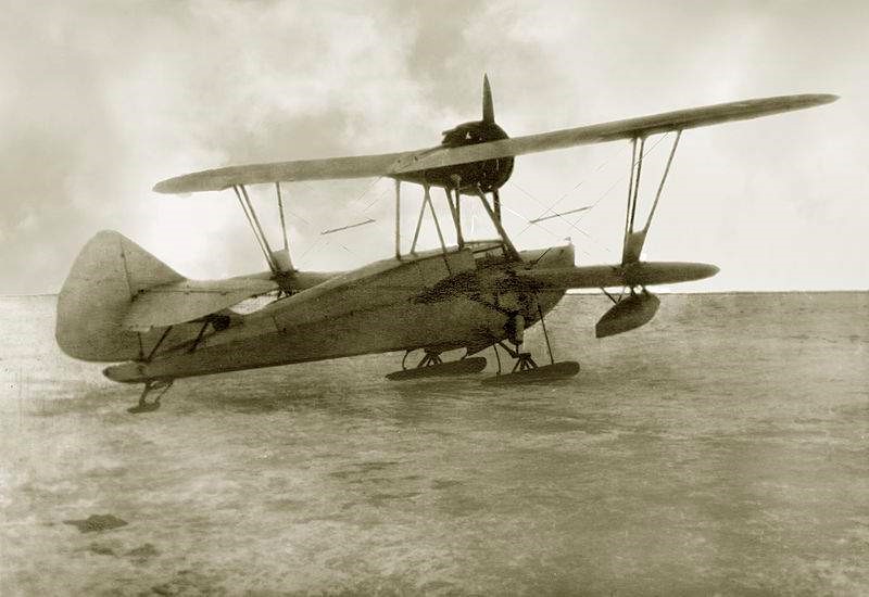
For operations on land, the MU-4 had a conventional landing gear with oleo-pneumatic shock absorbers and a tail skid. The main units retracted forward on the sides of the hull by means of a manual drive system. To allow winter operations the wheels could be replaced by skis.

The MU-4 tested with skis in the winter of 1937 – 1938.

The tail unit was of the conventional monoplane type with the stabilizers located high on the empennage and fixed by parallel struts in its lower part.

The MG-11F engine was installed on the upper wing in a tractor configuration protected by a Townend ring hood and moving a two-blade propeller. For winter, a special “winter” cowl was designed.

The MU-4 could carry two people, seated side by side in an enclosed, dual-control, glazed cabin.

The first prototype was finished in August 1937. Tests showed that the plane had good flight characteristics and could perform aerobatics. During the manufacturing tests this example was destroyed due to a construction defect. The engine fixing brackets to the gunwales were glued with a poor quality glue that ended up coming off. A short time later Mijelson would be imprisoned so the responsibility for further development passed to VV Nikitin.

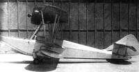
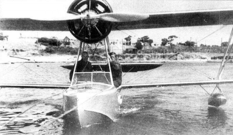
Mijelson MU-4/2 at Factory No.23.

The second prototype was submitted for testing in May 1938. Model tests were carried out at the NII GVF hydrostation located in Konstantinovska Bay in Sevastopol. The flights were carried out by test pilot GI Sergueyev. The MU-4 was presented as a simple plane to fly and capable of taking off and landing in small aquatic spaces.

MU-4/2 during factory tests in 1938.

It was proposed to build a series of 30 examples at Factory No.23, but after Mijelson ‘s conviction this decision was reversed. The Shavrov Sh-2 was produced in series, covering the same needs.

MU-4
Powerplant: 1 x 190 hp MG-11F
Wingspan of upper plane: 12.00 m
Wingspan of lower plane: 9.00 m
Wing area: 33.00 m²
Length: 8.70m
Height: 3.70m
Empty weight: 989 kg
Normal takeoff weight: 1255 kg
Wing loading: 36.4 kg/m²
Power load: 4.2 kg/hp
Fuel + lubricant capacity: 80 + 20 kg
Top speed: 173km/h
Cruising speed: 154 km/h
Service ceiling: 3400 m
Accommodation: 2

Mijelson-Morschijin U-3

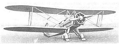
In the mid 1930’s Leningrad Factory No.23 was producing versions of the Polikarpov U-2 trainer. In parallel with the development of the serial versions U-2, AP and others, NG Mijelson and AI Morschijin proposed in 1934 the development of a version with a similar layout, but with larger dimensions and a more powerful M-48 engine of 200hp. The objective of this model was to obtain a medium training aircraft in which the students could continue after finishing the initial classes with the U-2.

Construction of the U-3 (Russian: Михельсон/Морщихин У-3) included a number of bolted duralumin aggregates. These aggregates were generally lighter. This, together with some decrease in the reserves of structural resistance, lightened the model. Other minor modifications were introduced with a view to improving performance.

The M-48 engine was protected by a hexagonal-shaped Townend cowling constructed of “Enerzh-6” stainless steel.

The U-3 was tested in 1935 but the results obtained were not much higher than those of the U-2, and the M-48 engine was not produced in series.

Mijelson PT/PSN Valk / Nikitin PT/PSN Valk

PT

Starting in 1933, a series of projects began to be developed in the USSR under the common name of PSN, acronym for P laner S petsialnovo N aznachenya or Gliders for Special Missions. Among these projects was SF Valk’s idea of using a glider with a torpedo and an infrared or radio guidance system to attack surface ships and naval bases.

This idea had its development in a series of projects known as:
LTDD – Letayushaya Torpeda Dalnevo Dieztvya (Long Range Flying Torpedo);
DPT – Dalni Planerni Torpedo (Long Range Glider Torpedo);
BMP – Bozduzhni Minni Planer (Airborne Mine Glider);

As a development of this conception, Mijelson would receive the task of building an experimental manned hydrofoil glider capable of carrying a torpedo and intended primarily to test remote flight control systems. This glider, called PT, was followed by a small series of copies that received the name PSN (Russian: Михельсон / Никитин ПСН).

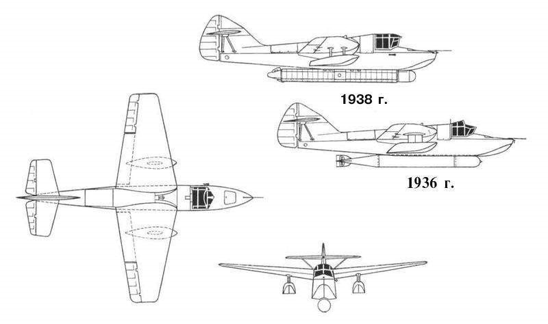
The PSN was designed as a small single-seater hydrofoil glider with stabilization floats located approximately halfway across the wingspan of each half plane. The entire construction was made of wood.

The wings presented high implantation with a trapezoidal shape in the plane. Louvered ailerons and flaps were included as control surfaces. The tail unit featured the outriggers braced by double struts high on the keel.

The pilot was located in a glass cockpit in front of the wing leading edge. At the bottom of the glider was fixed a torpedo.

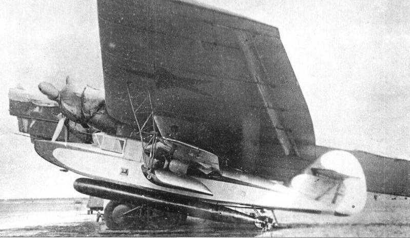
The PSN was carried by a Túpolev TB-3 or TB-7 mother bomber and was released at a pre-calculated height and distances between 30 and 50 km from the target. After launching its torpedo, the glider would land on the water.

A PSN hydrofoil glider with a torpedo under the wing of the Túpolev TB-3 mother plane.

In 1934 the first PT copies and their equipment were built and tested. The first 4 units were built in 1935 at factory No. 23 in Leningrad. In this case, it was a piloted glider version designed to evaluate the infrared guidance piloting system known as Kvant (Quanto). This project was developed under the direction of Mijelson and Nikitin was in charge of the production.

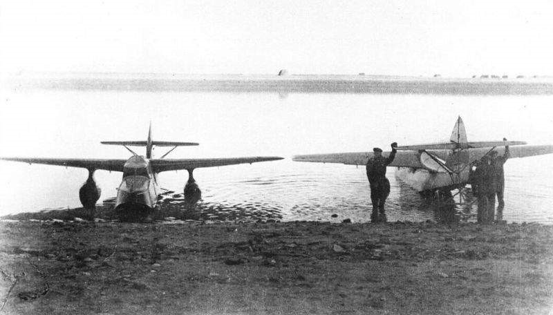
Two PT gliders during the water tests.

From June until October of August of 1936 at the Naval base Krechevits the first fixation tests PT were performed under a bomber Tupolev TB-3. During these tests the PT was piloted by N N. Ivanov.

Between 1937 and 1938 the construction of a small series of PT without a pilot was requested, which received the name PSN (or PSN-1 in some literature).

In general, 10 copies of the PSN-1 were built, which were used in different tests of the Kvant guidance system and an autopilot system developed at that time.

In March 1938, after the arrest of Mijelson, the works were interrupted. All produced copies of the PSN were destroyed.

PSN
Wingspan: 8 m
Wing area: 13.2 sq.m
Length: 8.9 m
Height: 2.11 m
Empty weight: 970 kg
Loaded weight: 1970 kg
Speed: 150 – 350 km / h
Dive speed: 500 km / h
Range: 30 – 35 km
Accommodation: 1

Mijelson, Nikolai Gustavovich

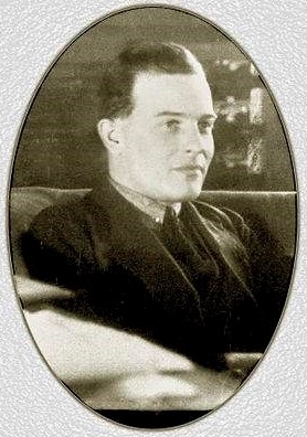
Nikolai Gustavovich Mijelson (in Russian: Николай Густавович Михельсон) was born in 1895 in Bielovostok, Grodnienski governor.

The first references to Mijelson appear after joining the construction bureau “Gamayún” in Saint Petersburg, directed by Schetinin and specialized in the design and construction of hydrofoils. Starting in 1912, after the incorporation of DP Grigorovich to the factory as technical director, Mijelson became his main collaborator, participating in the creation of all his designs during the pre-revolutionary period. Mijelson’s participation was decisive in the development of the famous M-5, M-9 and M-11 hydrofoils, participants in the First World War.

During the events of October 1917 Mijelson was in Krasnoyarsk where he met MM Shishmariov, Grigorovich’s former assistant. Together in 1920 and not without running into great dangers, he managed to move to Taganrog, as they had heard that the “Lieved” factory run by B. Levediev had been created there. The years of civil war ran and the friends were forced to avoid the white and red troops in combat.

The following year, together with Shishmariov and the engineer of the “Liebed” factory, formerly a naval pilot of the Denikin troops, VL Korvin-Kerber, he won a competition promoted by the VVS leadership for the project of a single-seater naval fighter with a Hispano-Suiza 200 hp engine. Construction of the prototype began in Taganrog. The new fighter, called MK-1 “Ribka” (Fish), was designed as a biplane with a monocoque structure that completely hid the engine. This structure used four plywood stringers and frames with holes to lighten the weight. The radiator was located in the center plane of the upper wing.

For the spring of 1922 the VVS made the decision to continue the construction of the experimental MK-1 “Ribka” in Petrograd, at the “Krasni Liotchik” factory. As a result, Mijelson headed there with the details and built components of the new fighter. The other co-authors were sent to Moscow to make themselves available to DP Grigorovich.

In Petrograd Mijelson completed the construction of the plane, but during the tests the prototype refused to take off from the water. The floats were too heavy for the low power of the engine. Measures to lighten the plane did not bring positive results either. Only when Mijelson removed the floats and replaced them with a train of wheels did pilot LI Giks manage to lift it up into the air. The aircraft proved to be well designed, but the low power of its engine did not allow it to go into series production. While waiting for a new engine, the plane was stored in a hangar at the small airfield on Kretovski Island where it was destroyed during a flood in 1924.

Mijelson continued to work at the “Krasni Liotchik” factory until the Department of Experimental Shipbuilding (OMOS) led by DP Grigorovich was transferred there from Moscow. From that moment on, Mijelson joined the group led by his former boss. During this period, he participated in the development of all OMOS works, including the SUVP passenger plane, the MRL-1 naval reconnaissance plane, the I-2bis fighter, the ROM-1 and ROM-2 open sea explorers. and the MUR-1 training scout. Many of these designs were unsuccessful, which was reflected in the collective’s psychological climate. For this reason, when it was decided to return Grigorovich with his collective to Moscow, Mijelson and another group of collaborators made the decision to remain in the “Krasni Liotchik” . Mijelson was in charge of the drawing department.

In 1929 Mijelson was arrested. This happened unexpectedly and was a continuation of the process that began with the arrest of DP Grigorovich and involved a significant number of OMOS workers. For a whole year Mijelson had been summoned to answer as a witness in the trials of DP Grigorovich, AN Sidielnikov, VL Korvin-Kerber and other colleagues, until his time finally came. Judged by article 58, Mijelson was sent to the first Sháraga TsKB-39 of the OGPU, where builders of the Grigorovich and Polikarpov collectives were already working. This collective in a very short time and under a strict supervision system managed to develop the I-5 fighter, the IZ gun fighter and the TB-5 bomber. In all these works Mijelson had an active participation.

In 1931 Mijelson was released and returned to Leningrad. Here at Factory No.23 (new designation of “Krasni Liotchik”) he began working as director of the construction department. In 1935 with the help of IV Chasovikov he created the PV-23 light seaplane and later devoted himself to improving the Polikarpov U-2 by creating the U-3 and U-4 trainers with improved aerodynamics.

Soon after, Mijelson would work on the MU-4, MU-5 and MU-6 training amphibians. The projects looked very promising, which was confirmed during testing of the second MU-4 prototype in Sevastopol. Almost parapelled Mijelson developed a lightweight torpedo boat named MP and was designed to be transported to the attack area under the wings of a TB-3 bomber. Once the torpedo was released, this aircraft was able to return by its own means to its base and land there.

These designs Mijelson could not finish. At the end of 1937 he was arrested again. Mijelson was charged under article 58 and on January 17, 1938, he was sentenced to the maximum penalty. The next 12 days were torture awaiting the announced end. Nikolai Mijelson was shot on January 29, 1938. His remains rest in an unidentified grave in Leningrad, presumably in the NKVD special cemetery “Levashovskaya Pustosh”.

The continuation of these projects was originally assigned to VL Korvin-Kerber and later to the young architect VV Nikitin, but soon they all ended up being closed. In the opinion of the NKVD an “enemy of the people” could not build anything good.

Mignet HM 1100 Cordouan

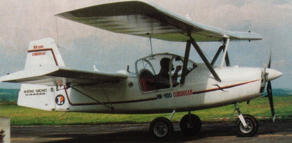
Avions Henri Mignet HM.1100 Cordouan first flew in 1998.

The type was not intended to be sold as a kit, but it meets the French ULM or ultralight category, having a maximum take-off weight under 1000 lb.

The fuselage is steel tube framed with a composite shell, and it seats two, side by side. It has a nose wheel undercarriage and although retaining the tandem wings (which traditionally do away with the need for ailerons) Mignet has incorporated ailerons on the rear wing, giving a classic three-axis control via rudder pedals and a single central control stick. If requested a two control model can be made.

Fitted with a Rotax 912, the prototype maximum speed is 117 mph and normal cruise 93 mph. It won’t stall, and it can take off fully loaded from a 260 ft grass strip, and land even shorter. Rate of climb is about 900 fpm.

The Cordouan’s forward wing is entirely free of pitch, control being effected through aerodynamic compensator. The ailerons are on the trailing edge of the rear wing. The fuselage is moulded in composite.

Mignet Aviation HM 1100 Cordouan
Engine: Rotax 912, 80 hp
Wing span: 7.30 m
Wing area: 18.50 sq.m
MAUW: 450 kg
Empty weight: 260 kg
Fuel capacity: 50 lt
Max speed: 190 kph
Cruise speed: 160 kph
Minimum speed: 65 kph
Climb rate: 5 m/s
Seats: 2
Fuel consumption: 14 lt/hr
Price (1998): 260 000 Fht

Mignet HM 1000 Flying Flea

Used by the French military for surveillance.
By 1998, 130 had been sold, including 25 to the French Army.

Mignet Aviation HM 1000 Balerit

Mignet Aviation produced the HM 1000 Balerit two seat side-by-side pusher entirely in dural, with the fuselage of welded tube and the wings in riveted sheet. The wings fold up for transport.

Mignet Aviation HM 1000 Balerit
Empty weight: 174 kg
Wing span: 8.55 m
Wing area: 19.25 sq.m
Fuel capacity: 42 lt
Certification: BCAR S
Engine: Rotax 582, 64 hp
MAUW: 450 kg
Seats: 2
Max speed: 150 kph
Cruise speed: 110 kph
Minimum speed: 60 kph
Climb rate: 4 m/s
Fuel consumption: 14 lt/hr
Price (1998): £23,265

Mignet HM 300 Flying Flea / HM 310 / HM 360 / HM 380

HM380

Mignet Do Brasil was formed early 1950s to build Mignet H.M.310 Estafette two-seat modernised version of the designer’s earlier Pou-du- Ciel light aircraft. A new development flown 1951 with Continental A90 engine.

The HM 360 is a single seater with very detailed plans in French, and English translation manuals supplied.
The HM 380 is a two seater side-by-side, with a wood fuselage. It is supplemental to the HM 360 set, redrawn in English, with added detail.

Options include Cosandey flap, ailerons, swept fin & rudder, tricycle gear and HIPEC® covering.

The HM380L is a set of plans in English for a steel tube fuselage version of the 380. Instructions are on plans. Flap plans included (Cosandey flap not required). Set is very complete showing engine installation, fuel system, wiring diagram, exhausts, engine mount, full size wing ribs, tailwheel, main undercarriage (Wittman type), etc. Hardware is AN standard. Materials are SAE and US standard. The Ladybug 380L ia a 2 seat side by side tandem wing aircraft that is great for training and familiarization for these type of aircraft.

The two seaters are flown from the front.

A considerably modified version of the two-seat HM.380 was developed by Mr Lederlin in France as the Lederlin HM.380L Ladybug. The prototype of this version on 14 September 1965, powered by a Continental C90.

Prototype Lederlin HM.380L Ladybug, Old Warden 1973.

Falconar Mignet HM 360 plans cost US$150 in 2010, with the 380 supplemental plans and additional US$50. Falconar 380L Ladybug plans sold for US$175 in 2010.

On June 30, 2019, Falconar Avia Inc closed for business and assets dissolved. The Master Sets (Original Drawings, Plans, Info Kits, Documentation) were available for sale and full transfer of rights included the MIGNET HM 360, HM 380, and 380 L for $2500 USD.

Mignet HM 360
Engine: 60 hp Continental or similar
Cruise speed: 80mph
Empty weight: 390 lbs
Wing Span: 21 feet
Gross weight: 700 lbs
Wing span folded: 8 feet

HM 360
Engine: Continental, 65 hp.
HP range: 65-100.
Length: 13 ft.
Wing span: 21 ft.
Wing area: 138 sq.ft.
Weight empty: 390 lbs.
Gross: 700 lbs.
Fuel cap: 14 USG.
Cruise: 95 mph.
Range: 330 sm.
Stall: 28 mph.
ROC: 1500 fpm.
Take-off dist: 130 ft.
Landing dist: 130 ft.
Seats: 1.
Landing gear: nose or tail wheel.

HM360
Engine: Continental C-65, 65 hp
HP range: 65-100
Height: 6 ft
Length: 13 ft
Wing span: 21 ft
Wing area: 138 sq.ft
Empty weight: 390 lb
Gross weight: 700 lb
Fuel capacity: 14 USG
Top speed: 124 mph
Cruise: 95 mph
Stall: 28 mph
Range: 330 sm
Rate of climb: 1000 fpm
Takeoff dist: 130 ft
Landing dist: 130 ft
Seats: 1-2
Landing gear: nose or tail

Mignet HM 360
Engine: 100 hp Continental or similar
Cruise speed: 100 mph
Empty weight: 390 lbs
Wing Span: 21 feet
Gross weight: 700 lbs
Wing span folded: 8 feet

Mignet HM 380
Engine: 60 hp Continental or similar
Cruise speed: 80mph
Empty weight: 580 lbs
Wing Span: 27 feet
Gross weight: 1100 lbs
Wing span folded: 10 feet

HM380
Engine: Continental C-65, 65 hp
HP range: 65-100
Height: 6 ft
Length: 13 ft
Wing span: 21 ft
Wing area: 138 sq.ft
Empty weight: 390 lb
Gross weight: 700 lb
Fuel capacity: 14 USG
Top speed: 124 mph
Cruise: 95 mph
Stall: 28 mph
Range: 330 sm
Rate of climb: 1000 fpm
Takeoff dist: 130 ft
Landing dist: 130 ft
Seats: 1-2
Landing gear: nose or tail

HM 380
Engine: Continental C-90, 90hp.

Mignet HM 380
Engine: 100 hp Continental or similar
Cruise speed: 100 mph
Empty weight: 580 lbs
Wing Span: 27 feet
Gross weight: 1100 lbs
Wing span folded: 10 feet

380L Ladybug
Engine: Continental C90
Wing span front: 26 feet
Wing span rear: 19.08 feet
Wing area: 180 sq. feet
Length: 15.07 ft
Empty weight: 795 lbs
Gross weight: 1330 lbs
Vne (never exceed speed): 124 mph
Cruise speed: 113 mph
Range: 130 miles
Stall: 28 mph
Takeoff distance: 500 feet
Landing distance: 500 feet

Mignet HM 290 Flying Flea / HM 293 / HM 295 / Falconar Avia 290E/293E / Rodolphe Grunberg HM 293

HM290

Development has continued since World War 2, the basic post war single seat version being the HM-290 with a 25 hp Poinsard engine.

The HM 290 Series included:
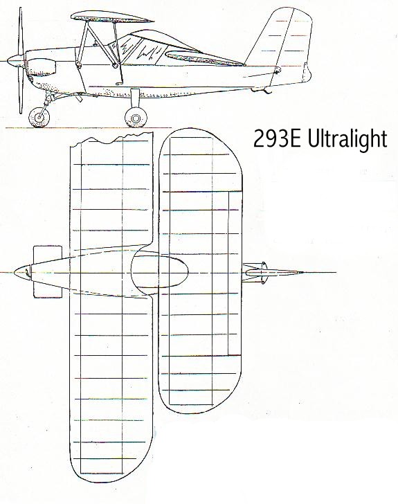
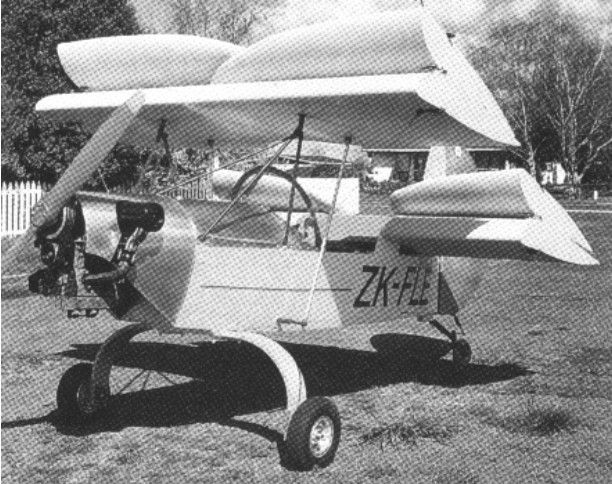
F293E ultralight model- for medium size pilot
F295E ultralight model- for medium size pilot (with simplifications)
HM290 amateur built model – for small pilot
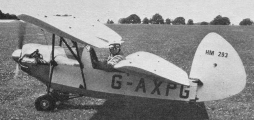
HM293 amateur built model – for medium size pilot

HM293

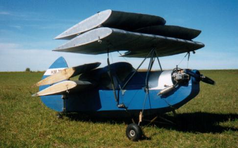
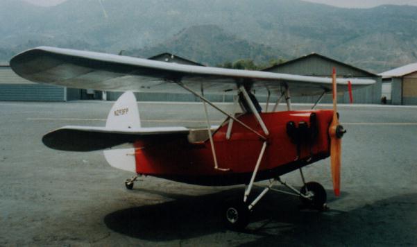
These tandem wing aircraft feature a large speed range, stall resistant, and spin proof. Both wings lift and being small size, minimal space is needed to build. Landing gear arrangement: tail dragger or tri-gear.
Options include swept fin and rudder.

Falconar devised design changes for easier construction, modern materials, Delrin bearings, tri-gear and HIPEC® covering.

Rodolphe Grunberg has redrawn the 1940s HM.293 plans, updated them for 1990s materials, and fitted new light weight engines. Over 40 Grunberg HM.293s were reported either flying or close to completition in France in 1998.

Rodolphe Grunberg HM 293

In 2010 Falconar MIGNET “Flying Flea” plans cost: HM290E, HM293E, HM290, HM293 cost US$65. Falconar Avia produced kits as an LSA.

HM 293

On June 30, 2019, Falconar Avia Inc closed for business and assets dissolved. The Master Sets (Original Drawings, Plans, Info Kits, Documentation) were available for sale and full transfer of rights included the MIGNET “Flying Flea” HM 290/293, 290/293 E, F295 E, and 295 F for $4500 USD.

Gallery

“Flying Flea”
HM 290E/293E ULTRA LIGHT
Engine: 25/30 hp Hirth or Rotax
Cruise speed: 60 mph
Length: 13 ft
Empty weight: 246 lb
Gross weight: 476 lb
Wing span: 20 ft

HM290/HM293 amateur built
Engine: 50/60 hp Little Demon (VW) or similar
Cruise speed: 90 mph
Length: 12-13 ft
Empty weight: 360 lb
Gross weight: 580 lb
Wing span: 18-20 ft

HM290/293
Engine: VW, 60 hp
HP range: 50-60
Height: 5.5 ft
Length: 13 ft
Wing span: 20 ft
Wing area: 113 sq.ft
Cruise: 90 mph
Stall: 28 mph
Range: 300 sm
Rate of climb: 800 fpm
Takeoff dist: 150 ft
Landing dist: 150 ft
Fuel capacity: 10 USG
Empty weight: 350 lb
Gross weight: 600 lb
Seats: 1
Landing gear: nose or tail

HM 293
Engine: VW, 60 hp
Speed max: 110 mph
Cruise: 90 mph
Range: 300 sm
Stall: 28 mph
ROC: 1400 fpm
Take-off dist: 150 ft
Landing dist: 150 ft
Fuel cap: 10 USG
Weight empty: 350 lbs
Gross: 600 lbs
Height: 5.5 ft
Length: 13 ft
Wing span: 20 ft
Wing area: 113 sq.ft
Seats: 1
Landing gear: nose or tail wheel.

Falconar Avia 290E/293E
Engine: Kawasaki, 30 hp
HP range: 25-35
Length: 13 ft
Wing span: 20 ft
Wing area: 117 sq.ft
Empty weight: 246 lb
Gross weight: 476 lb
Fuel capacity: 5 USG
Cruise: 55 mph
Stall: 28 mph
Range: 290 sm
Rate of climb: 500 fpm
Takeoff dist: 180 ft
Landing dist: 150 ft
Cockpit width: 23 in
Landing gear: nose or tail

Rodolphe Grunberg HM 293
Engine: 30-40 hp
Wing span: 6.10 m
Wing area: 12 sq.m
MAUW: 250 kg
Empty weight: 117 kg
Fuel capacity: 30 lt
Max speed: 130 kph
Cruise speed: 90 kph
Minimum speed: 30 kph
Seats: 1
Plan price (1998): 295 Fnc

HM293E

Mignet HM 14 Flying Flea

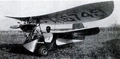
The first Flying Flea took to the air back in 1933 and quickly earned a reputation for being temperamental. Mignet was a furniture manufacturer, and named his creation “Le Pou de del,” or Louse of the Sky. It started out to be Everyman’s Airplane, something you could build for $500, complete, in the Depression years. Mignet’s Flea carried a 17-hp engine and had a speed range from 25 to 62 mph.

Mignet HM 14 Flying Flea Article

The Pou de Ciel (Flying Flea) was introduced to the public during the Paris Aero Salon in 1935.

For simplicity the top wing pivoted about the front spar and was tilted up and down for longitudinal control. There were no ailerons, turns being made by the rudder alone. Mignet’s Pou and his book Le Sport de l’Air started a craze for do it yourself aircraft in the 1930s. Translated to English by the British Air League which did not include a true and correct C of G situation. This resulted in numerous crashes. Flea fever swept France, Britain and America. In 1935 some 600 Flying Fleas were under construction in the British Isles alone. Most stayed firmly on the ground. Ignorant of the ways of aircraft, they built their Fleas too heavy, or used unsuitable engines, so that the machines would do little more than tear around re¬fusing even to hop like their namesakes. Most were fitted with the 25 hp Scott or Douglas engine. It was a blessing in disguise, for the Pou du Ciel had an inherent design fault. The trouble lay in Mignet’s tan-dem wing configuration: the rear wing was fixed while the incidence of front surface could be varied to give control in pitch. If the front wing was allowed to stall, the nose would drop and because of an obscure inter¬ference effect between the two wings the aircraft would dive ever steeper until it either became stabilized in an inverted posi¬tion from which recovery was impossible, or struck the ground. Accidents showed that the aircraft became uncontrollable if the wing incidence exceeded 15 degrees, and British Fleas were promptly grounded. It became illegal to fly unmodified Flying Fleas after June 1937.

Mignet fixed the problem and continued to build and develop Poux until his death in 1965.

Douglas developed an engine model specifically for aircraft, with longitudinal finning; the Scott company brought out their 750cc inline model A.25; and Sir John Carden set up in production with a modified version of the reliable Ford 10 engine.

E.D.Abbott Ltd coachbuilders of Wrecclesham, Farnham, Surrey, UK, set up production of kits (at £90) and complete aircraft (at £198). Flight test took place at Heston.

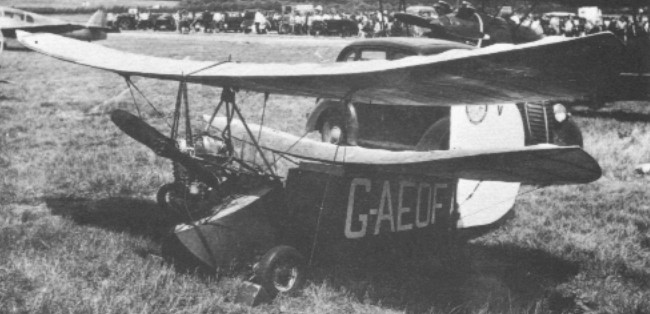
G-AEGD cn CP.1 was modified to ‘Cantilever Pou’ design of L.E.Baynes with strut-braced wings and fitted with an enclosed Carden-Ford engine. It was registered on 15 April 1936, sold in January 1936, and cancelled in February 1943. Following G-AEGD were G-AEJC cn CP.3 and G-AEJD cn CP.4. G-AEJC was registered on 27 July 1936 and cancelled in December 1937. G-AEJD was used for stall investigation.

Gallery

Mignet HM 14 Pou de Ciel / Flying Flea
Engine : Bristol, 35 hp
Length : 11.483 ft / 3.5 m
Height : 6.562 ft / 2.0 m
Wingspan : 16.732 ft / 5.1 m
Max take off weight : 441.0 lb / 200.0 kg
Weight empty : 242.6 lb / 110.0 kg
Max. speed : 65 kt / 120 km/h
Crew : 1

Mignet Pou-du-Ciel (Flying Flea)
Engine: 75 hp McCulloch horizontally opposed
Maximum speed: 91 mph (146 km/h)
Empty weight: 421 lb (191 kg)
Maximum weight: 643 lb (292 kg)
Span: 18 ft 2 in (5.5 m)
Length: 12 ft 6 in (3.8 m)
Height: 5 ft 8 in (1.7 m)
Wing area: 108 sq ft (10 sq m)

Engine 22-38 hp.
Gross Wt. 700 lb
Weight empty 350 lb (160 kg.)
Fuel capacity 12 USG
Top speed 56 mph
Stall 35 mph
Climb rate 500-600 fpm
Ceiling 16,400 ft
Seats: 1
Length 13 ft. (3.96 m)
Wing span 22 ft. (6.7 m)
Max cruise 60 mph (96 kph)
Range 200 miles (320 km)

Engine: ABC Scorpion, 35 hp
Top speed: 80+ mph
Cruise speed: 70 mph
Landing /TO speed: 30 mph
Landing dist: 150 ft
TO dist: 200 ft
Fuel capacity: 7 USG
Range: 280 mi
Empty wt: 316 lb