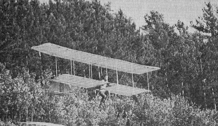
In the ski areas of New England, USA, Terry Sweeney of New Hampshire experimented with some Chanute typ. He and some friends made many flights, learned much and had fun. Their gliders replaced the older airfoils with more modern versions.
In the ski areas of New England, USA, Terry Sweeney of New Hampshire experimented with some Chanute typ. He and some friends made many flights, learned much and had fun. Their gliders replaced the older airfoils with more modern versions.
On the east coast, USA, in the summer of 1970, Robert G. Mixon of Miami, Florida, built and flew a Chanute-type biplane based on a plan found in a 1909 Popular Mechanics.
The local paper ran a front page headline “Those Magnificent Men In Their Flying Machine” on 15 June 1970. A local TV station even took some footage of a cliff launch. Mixon did it out of frustration due to the high cost of conventional flying.
Later, he offered plans, because of a large number of requests for his story which appeared in the February 1971 issue of Sport Aviation.
Pelzner was a builder of doppeldecker hangegleiter. In 1921 and 1922 he carried off many prizes. He built all his own craft and developed a simple structure that proved strong enough to carry him safely on flight after flight without serious mishap, yet light enough for him to control flight by bodily movements, changing the centre of gravity to trim the aircraft and overcome the upsetting effect of gusts or turbulence.
Pelzner’s gliders were astonishingly cheap despite financial trouble and inflation in Germany they cost him less than 20 marks to build. Derigged, they were small enough to be loaded onto a passenger train as traveller’s luggage at no extra charge; the parcel measured about 2.7m long, 1.3 m high, but only 50 cm thick.
The various Pelzner gliders differed a good deal in size and detail, although all were built roughly to the same basic scheme. The earlier models were built smaller and very light; 5.4 m span with total wing area of 14 sq.m. The weighed less than 10 kg. The later types spanned up to 7 m with areas of 16.5 sq.m, and weighed twice as much. Probably as Pelzner’s skill improved he was able to control bigger and more efficient gliders.
The framework was two tapered longerons, a shoulder width apart, running fore and aft with the lower wing main spars running cross wise and attached with bolts. At the rear these two main members were drawn together to support the tail unit, and from the tail to the upper end of the main wing struts two diagonal members ran. This basic framework was of oval or streamlined section timber, 2.5 cm by 4 cm in cross section where the loads were greatest, thinning down to 2 x 3 cm elsewhere. The upper and lower wings both had two spars, the front spars being 4 cm by 0.5 cm section, the rear spars 3.5 x 0.8 cm on the lower wing and 3.6 x 1.1 cm on the upper. Light curved ribs were bound to the spars, and the two wings were joined by light vertical struts, the outer ones being spindled I section to save weight. The whole structure was braced with wire.
Pelzner covered his surfaces with oiled paper, glued onto the underside of the ribs of wing and tail. The leading edge of the lower wing was formed by the front spar, but the upper wing apparently had a light front member of wood or wire which gave a stiff entry to the primitive aerofoil. Some models had double thickness paper covering around the leading edge. The earliest models had no movable control surfaces at all, but later Pelzner fitted a rudder which he controlled by means of a sling around his right hand – a forward movement for a left turn, a backwards push for a right turn.
To manage these craft Pelzner worked out an athletic style of flying. At the 1921 meeting he accumulated a total flying time of 38 minutes, higher than any other pilot. He did this in a total of 62 flights aeraging over a half a minute each, some of them covering 400 and 500 m at his best glide ratio of about 6 to 1. In cash prizes he paid for his gliders hundreds of times over.
After monoplane glider flights the future was clearly not biplanes. Pelzner played little in the subsequent development of gliding.

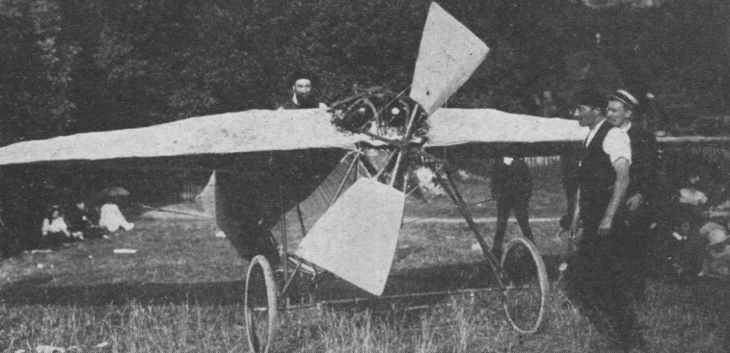
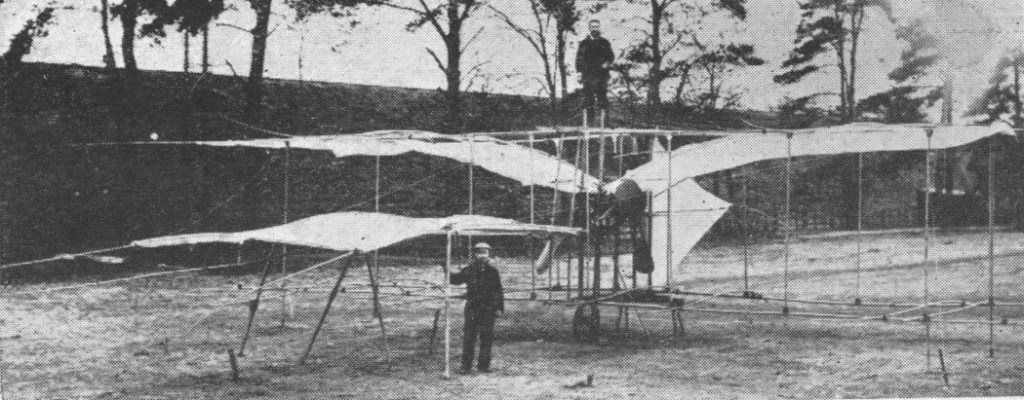
Bellamy’s later tailless monoplane, tested at Petersham Meadows in August 1908 did not fly, but taxied quite quickly along the ground.
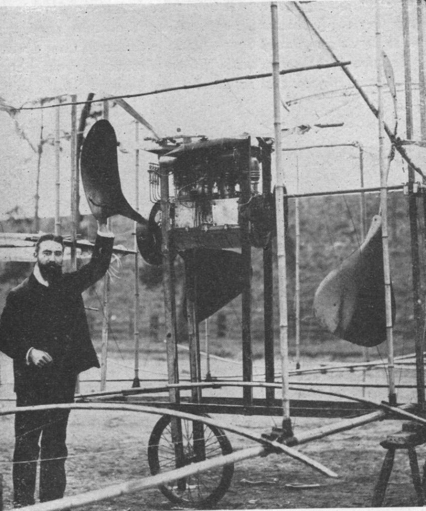
An early enthusiast at Weybridge, UK, Mr Bellamy built the bamboo and canvas-covered biplane.

In the late 1930s, Belgian aircraft maker Constructions Aéronautiques G. Renard developed the R.35, a sleek, pressurised airliner built for long-distance travel. Designed to serve SABENA’s route to the Belgian Congo, the R.35 featured a low-wing monoplane layout with three engines and retractable landing gear.

Alfred Renard initiated the design in 1935. SABENA requested a three-engine configuration, prompting a metal monoplane that could seat 20 passengers in a pressurised cabin. On April 3, 1936, an order for a single prototype was confirmed. Though compatible with more powerful engines, the prototype used less powerful Gnome-Rhône 9Ks.
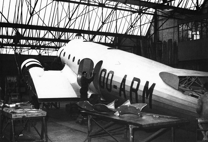
By early 1938, the R.35 was ready for testing. On April 1, it stood on Evere airfield, poised for high-speed taxi trials before a crowd of VIPs and journalists. After one ground run, it unexpectedly lifted off during the second. The pilot, Georges Van Damme, tried to complete a circuit, but the aircraft dove suddenly and crashed, killing Van Damme.
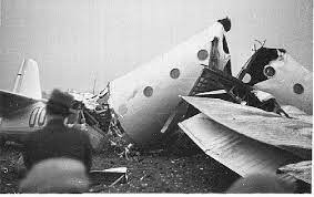
With the cause undetermined, SABENA withdrew its support, and the R.35 project was abandoned.

Powerplant: 3 × Gnome-Rhône 9K, 560 kW (750 hp) each
Wingspan: 25.50 m (83 ft 8 in)
Length: 17.50 m (57 ft 5 in)
Wing area: 87 m2 (940 sq ft)
Height: 5.50 m (18 ft 1 in)
Empty weight: 6,100 kg (13,448 lb)
Max takeoff weight: 10,500 kg (23,149 lb)
Capacity: 20 passengers or 2,000 kg (4,400 lb)
Crew: 3 (2 pilots and radio operator)
Maximum speed: 435 km/h (270 mph, 235 kn) at 5,000 ft (1,500 m)
Cruise speed: 350 km/h (220 mph, 190 kn)
Range: 1,800 km (1,100 mi, 970 nmi)
Service ceiling: 9,000 m (30,000 ft)


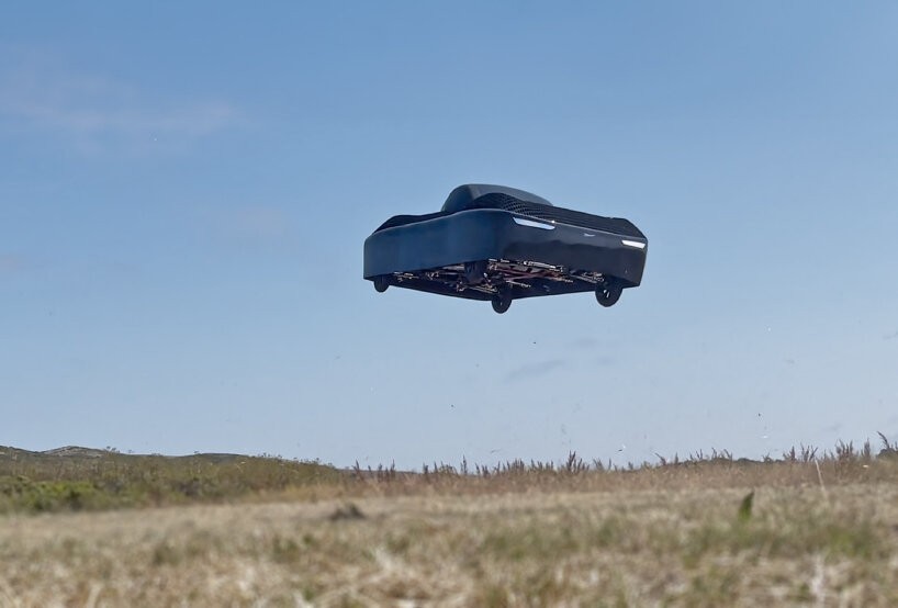
Alef Aeronautics offers its own eVTOL A flying car, a concept flying car that would have a driving range of 200 miles and a flight range of 110 miles.
The design has a car-like exterior, and does not have any exposed propellers for added safety and to drown the loud whirring sounds and also save space. The Alef flying car is all-electric and anchor key components such as Distributed Electric Propulsion (DEP) – which helps the airflow be evenly distributed – triple to octuple redundancy of all key components, real-time and pre-flight diagnostics to always keep the drivers informed of their drive or flight, glide landing, and even a full-vehicle parachute in case of emergencies.

Alef Aeronautics shares in the release that the 300,000 USD (2025) Alef flying car would be developed using the latest hardware and software technology and end up being lightweight packs with long-lasting components, software simulators and analysis, and rigorous flight testing. The team is planning to begin production and deliver the first batch in 2025.

Alef Aeronautics’ drivable flying car takes its maiden flight in a city field. On February 19th, 2025, its test model takes off, even flying over another vehicle. In a LinkedIn post, Alef Aeronautics CEO Jim Dukhovny writes that the video showcasing the flight is ‘the first documented, verifiable flight of a flying car (an actual car, with vertical takeoff, non-tethered).’
The vehicle comes with a gimbaled cabin design to keep it stable as it moves through the air as well as an elevon system to control the vertical and horizontal movement of the Alef Aeronautics flying car and its tilting.
Presently, the Alef Aeronautics flying car is the first vehicle with vertical takeoff to receive FAA permission to fly in the US (FAA Special Airworthiness Certificate).
While the Alef Model A is the commercial version, the test model is the Alef Model Zero. It is solely used for research and development in the hopes of becoming the actual Alef Model A.
Aero Gare
Mojave CA.
USA
1987
Aero Composite Technology Inc
Somerset PA.
USA
LSA builder
The 1921 V.B.L.-1, built by Aerial Transport Corp, was an open cockpit biplane described as an “express transport of three-ply construction.” 1922 Eaton Chronicles reported that Rogers Construction Co “… takes over the building of a Sport Biplane designed by C H Day of the defunct Aerial Transportation [sic] Corp.” Then in 1925, “Charles ‘Pop’ Dickinson buys the C D Air Express from Rogers,” which is described as a C H Day design. This would be conclusive proof that VBL-1 and CD Express are one and the same.
New York NY.
USA
Built the V.B.L.-1 in 1921
