Richard TOM-1

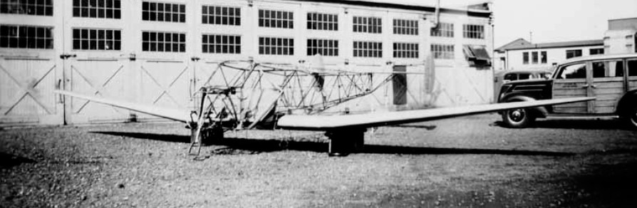
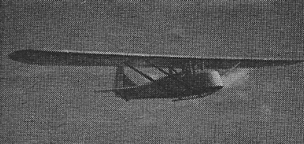
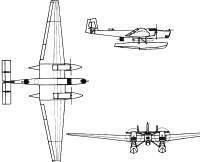
During his years in the USSR, French aircraft builder Paul Aimé Richard designed and built the Richard TOM-1 (Russian: Ришар ТОМ-1) Naval float bomber and torpedo boat. Only one prototype was built that was not produced due to the introduction of a navalized version of the Tupolev TB-1 with similar features and capabilities, but cheaper and easier to build.

The projecting task of the Open Sea Torpedo Boat or TOM was assigned to the KB led by Richard in late 1928. Several Soviet engineers participated in its development, who would soon achieve international renown for their creations. Notable among them were: II Artamonov, DM Jomnski, D. Samsonov, SA Lavochkin, IV Ostoslavski, MP Mogilievski, AL Gimmelfarb, GS Yelenievski, ZI Zhurbin, NI Kamov, MI Gurevich, SP Koroliov, IV Chetverikov, NK Skrzhinski, GM Beriev, IA Berlin, DA Mikhailov, VB Shavrov, GM Mozharovski, among others.

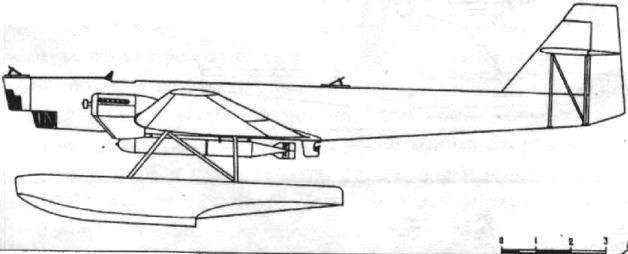
The TOM-1 was envisioned as a large monoplane of all-metal construction with floats. All the coating was made with smooth duralumin sheets of 0.5 – 0.6 mm, which gave it good aerodynamics. The structure was also designed entirely in duralumin, which was uncharacteristic of Soviet aircraft construction for those years.

The very thick wing with a 33 meter span had a rectangular midplane that was joined to consoles with a trapezoidal shape in the plane and marked narrowing towards the ends. The wing had a Sen-Sir-60 profile, with two skeletal spars and laminated ribs with large circular and oval holes to reduce weight. These ribs were located at a distance of 0.4 meters (quite compact for Soviet standards of the time). The segments of the stringer structure were achieved by joining two grooved pieces to form a kind of rectangular tube. Louvred flaps, capable of tilting downward at 40º angles, were located along the entire span of the trailing edge on the consoles.

The fuselage was a monocoque structure with the frames every 0.4 meters. The stringers were located every 150 mm, both in the fuselage and in the floats.

The tail unit was located high with triple empennage and was braced by means of N-pillars. The tail rudders incorporated trimmers to reduce the effort on the controls.

The large floats were fixed to the fuselage by means of 4 struts with tensioners between them.

The whole construction of the TOM-1 was quite light and very strong, but it was very technically demanding and expensive, almost twice that of the similar TB-1, and required a great deal of expensive sheets of duralumin, of which a considerable part was lost when drilling to reduce weight.

The two 680 hp BMW VI engines located on the wings.

The armament consisted of three firing points with PV-1 machine guns. These points were located fore and aft and a third in a retractable turret located in the lower section of the fuselage.

In the ventral zone, between the floats, one or two torpedoes could be fixed, developed by the OsTex Byuró.
The model was developed by the workshops located in the same KB building. On July 3, 1929 the project was completed and signed by PA Richard, his deputy DM Jomski and specialist SA Lavochkin.

In the fall of 1930, the plane was built and on January 1, 1931 it was transferred to Sevastopol for testing.

Assembly and preparation for testing were extremely lengthy. The plane was only ready in August. During the tests, carried out by pilot NI Kamkin with NI Kamov as engineer in charge, the aircraft presented acceptable performance. However, the new torpedo bomber was similar in capacity and performance to the TB-1 bomber and Tupolev was already successfully projecting a navalized version of this giant known as the ANT-4P. Building a similar plane, expensive and developed with unusual materials, was considered little objective. Only the prototype was built.

In 1931 Richard left the USSR due to the lack of new orders.

TOM-1
Engines: 2 x 680 hp BMW VI
Wingspan: 38.00 m
Length: 19.95m
Wing area: 120.00 sq.m
Empty weight: 5255 kg
Normal takeoff weight: 8030 kg
Top speed: 210km/h
Cruising speed: 182 km/h
Practical ceiling: 5500 m
Armament: 3 x 7.62mm PV-1 machine guns
Bombload: 1000 kg of bombs or two torpedoes
Accommodation: 4-5
Richard Commuter

The Commuter, a high-wing cabin monoplane, features all metal construction with no complicated double-curvature skin panels. The two-place taildragger carries 125- to 150-hp Lycoming powerplants. Persons sit in side-by-side fashion.

Wingspan 25’
Length 19’9”
Gross Wt. 1500 lb
Empty Wt. 805 lb
Fuel capacity 50 USG
Top speed 150 mph
Cruise 140 mph
Stall 40 mph
Climb rate 900 fpm
Takeoff run 1200 ft
Landing roll 1500 ft
Range 900 sm

N.B.Rich Airplane Co .Twin 1-X-2 / Rich-Twin

Since soloing in 1931, Bud Rich had owned and flown many aircraft, and frequently considered the advantages of continuing flight should one of two engines cut out. He put ideas and sketches down on paper.

At that time, Nelson Barnard Rich was instructing a course in practical-applications for aircraft students at M.I.T. He found three graduate students shared his enthusiasm for his basic plan for a twin-engine airplane. Soon, they were supplying the needed engineering. Bud provided materials, mechanical skills and space at his “Government Approved Aircraft Repair Station #226” at the Boston Airport.

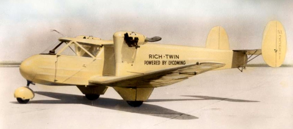
Those three young engineers were James (Jim) Kendrick (later with Lockheed); Holden (Bob) Withington (later V.P. of Boeing); and, in particular, William (Bill) Cook (also V.P. with Boeing and author of the incomparable book: “The Road to the 707”). The name “Rich-Twin” was given to it in Ohio by men from Lycoming who had generously provided its 75 hp engines and worked with Sensenich for efficient propellers. They had this name painted on the ship’s smooth, yellow fuselage when Bud and his wife Alberta (Berta) had flown it to Cleveland’s last Air Show before World War II.

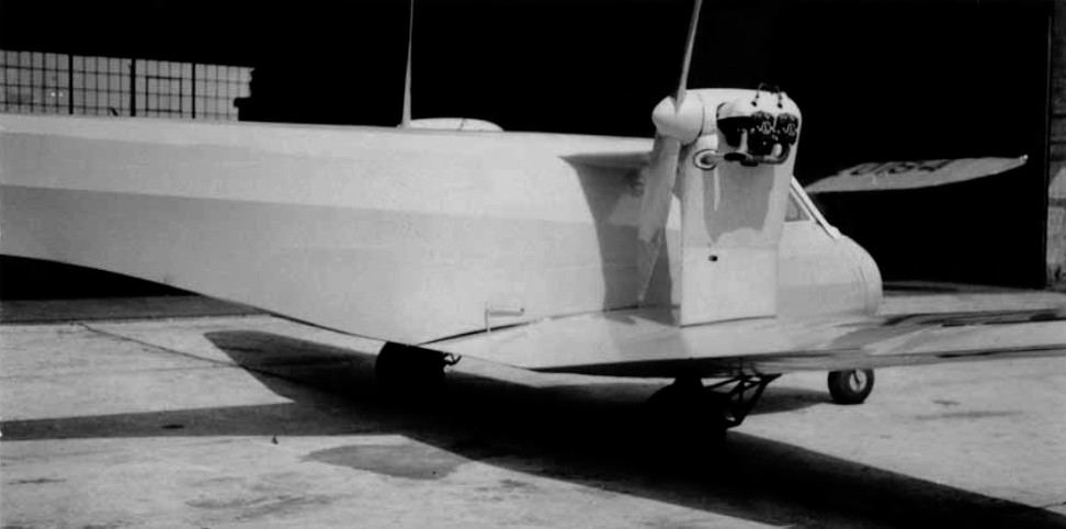
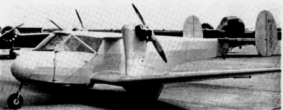
A low wing cantilever monoplane. the fuselage is a fabric-covered welded steel tube structure, with an enclosed cabin. Rectangular welded-steel framework fuselage covered with fabric. The cabin is in the nose of the fuselage seating two side-by-side with dual controls. Large entrance door on each side of the cabin. Baggage space behind seats. The wings are full cantilever, semi-monospar of plywood with rigid box spar and nose section, nine-foot wing flap with three positions. Tail Group; fabric covered welded steel tube structures, twin fins and rudders, tail plane braced by Vee struts. Landing gear; tricycle type, steerable nose wheel, partly retractable landing wheels. Plexiglas windshield.

A rectangular centre-section carries at its extremities two pylons for the engines, which are braced to the top of the fuselage longerons, and the main landing-wheel housings. Outer tapered wing sections. Wing structure of wood with two spruce and plywood box-spars and plywood covering. Single three position landing flap of duralumin construction under centre section.

Braced monoplane type tail unit with twin fins and rudders, Welded steel framework with fabric cover.
Tricycle type undercarriage. Mainwheels enclosed in streamline housings, are semi-retractable. Goodrich tires. Steerable nosewheel. Oleo-pneumatic shock-absorber struts. Hayes hydraulic brakes.

Two engines mounted on welded chrome molybdenum steel-tube pylons, one on each side of the fuselage , at the extremeties of the centre-section and driving pusher airscrews.

Instruments: Compass, airspeed indicator, rate of climb indicator, sensitive altimeter, turn and bank indicator, electric clock, fuel pressure gauge and a standard group of engine instruments, including Waltham tachometers and oil gauges.

Test Flight – 1939
Bud presses RIGHT rudder pedal. The ship’s response begins another twisting summersault. This time Bud makes an immediate correction. He is aware that the airplane had tried to fall to the left. Close to laughing, he knows an answer is being revealed to him.

By pressing LEFT rudder pedal very lightly he is not surprised that his previously recalcitrant X-Ship responds immediately to correction of an attempted tumble to the right. No further tests are needed. It’s evident that the near fatal lack of control had occurred because during final checkup before the test flight, a trusted mechanic had too smartly thought that the fuselage interior’s carefully engineered CROSS-LINED control cables, should be more normally straight-lined. So, he changed – from correct to incorrect! Although now knowing that control cables are at fault, Bud faces the need to use right pedal for left turns, and left pedal for right turns. He manages an approach to landing, but is dismayed to have to abort it … a learning experience.

Far from easy, he again circles the airport, and is delighted with a short landing run due to its design incorporating one of the world’s first landing wheel on the nose. He taxies carefully back to the hangar. Many well wishers and reporters rush to greet him, but, scarcely noticing them, he immediately goes into the fuselage and returns the rudder cables to proper cross-line position.

Gasping surprise ripples through the onlookers as he re-enters the cockpit, starts the engines, taxies out on a runway and with notably short take-off run is again airborne.

Bud resumed his experimental airplane’s test flight. Comfortably circling the field twice, he landed with ease and taxied back to the relieved group of onlookers. This time he talks good-naturedly with them, expressing appreciation for their interest.

After Bud had successfully test-hopped it in April of 1939, it was featured in publications such as Janes, Aerosphere, Aero Digest, and others. All of their original blue prints and drawings have been preserved.

Bud passed on peacefully at home in Titusville, Florida on March 15, 1998.

Gallery

Rich-Twin 1-X-2
Engines: 2 x Lycoming GO-145-C1, 75 hp at 3100 rpm
Propellers: Sensenich
Span: 35 ft / 10.67m
Length: 22 ft / 6.7m
Height: 6 ft 8 in / 2m
Wing area: 140 sq.ft / 13 sq.m
Empty weight: 1,000 lb / 454 kg
Useful load: 600 lb / 272.4 kg
Gross weight: 1,600 lb / 726.4 kg
Wing loading: 11.5 lb/sq.ft / 56.1 kg/sq.m
Power loading: 10.7 lb/hp / 4.85 kg/hp
Fuel: 26 USgal
Oil: 2 USgal
Max speed: 135 mph / 216 kph
Cruise: 115 mph / 184 kph
Landing speed: 48 mph / 77 kph
Initial ROC: 850 fpm / 260 m/min
Service ceiling: 14,000 ft / 4270m
Cruise range: 405 miles / 648 km

Ricci R.6

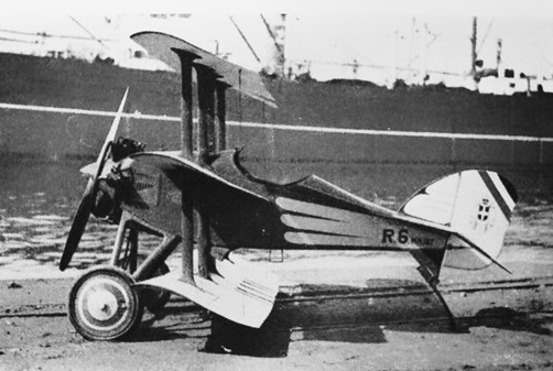
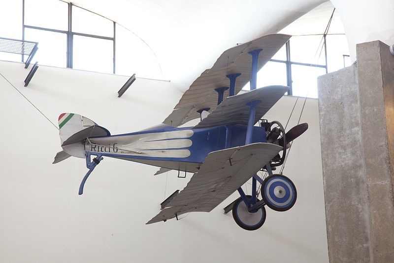
The Ricci 6 was a small triplane designed by Umberto and Ettore Ricci. It flew for the first time in 1918 in Bagnoli piloted by B. Albertazzi. It was simple and robust; it had a wingspan of just 3.50 m when it was first presented in 1920 at the Paris motor show. During the demonstration for the anniversary of the 1920 victory, he took off from the Pincio in Rome, throwing leaflets over the city. A second R 6 with Anzani engine was built with a 6-cylinder engine from the Bacini e Scali Company in Naples. Completing military tests, the R6 was delivered to the Air Force receiving the MM167 serial number.

A replica, made with original pieces of the first example in 1967, is exhibited at the Leonardo da Vinci National Museum of Science and Technology in the aeronaval pavilion.

Engine: 40 hp Anzani
Wingspan: 3.50 m
Wing area: 11 m²
Length: 3.75 m
Height: 2.4 m
Empty weight: 150 kg
Loaded weight: 260 kg
Max speed: 150 km / h
Endurance: 3 hr

Rhӧn-Rossiten-Gesellschaft / RRG Prüfling

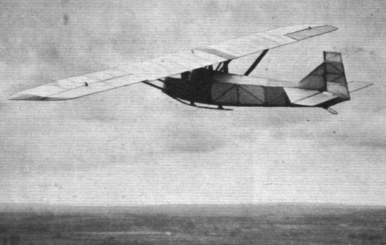
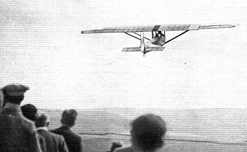
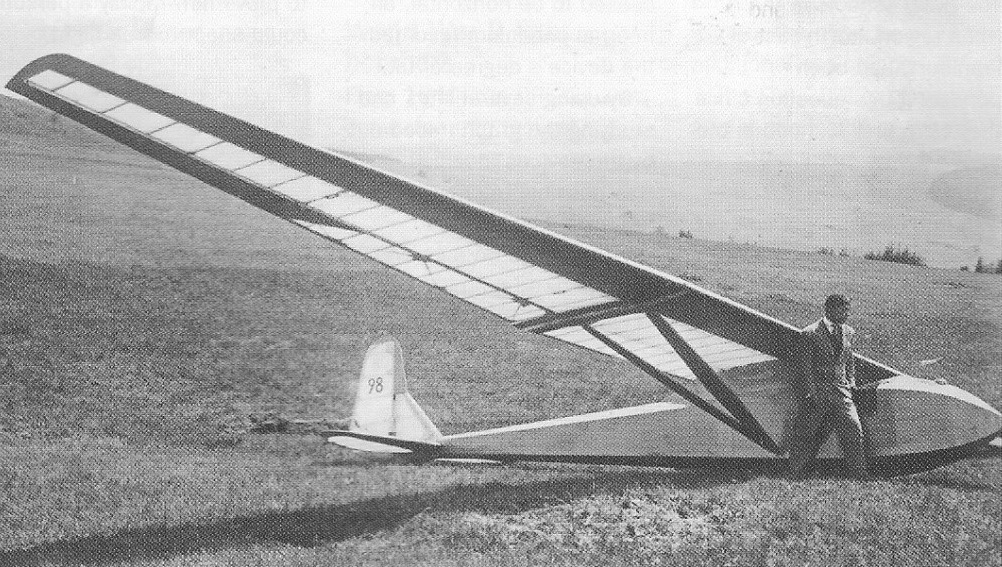
At the end of 1925 at the Martens gliding school on the Wasserkuppe into Rhön-Rossitten Gesellschaft (RRG), Martens chief instructor Fritz Stamer and Alexander Lippisch were brought together to produce two such gliders and within a few days the Zögling (English: Pupil) and the Prufling designs were complete. Some parts, for example the wings and to a lesser extent the horizontal tails, of the two aircraft were similar.

Both had almost rectangular, two-spar, wooden structured, two piece wings with fabric covering everywhere except the leading edges, which were plywood covered. The Prüfling’s wing tips were more rounded and its span 500 mm (19.7 in) greater. They both had simple ailerons reaching to the tips, where they were cropped, though the Prüfling’s were a little longer. Both had triangular tailplanes, carrying elevators that were rectangular apart for a cut-out for rudder movement, though the Prüfling’s tailplane was more strongly swept and was broader in chord.

The major differences between the two were in the fuselages. The Zögling had a very simple open frame girder fuselage, the Prüfling a more conventional hexagonal cross section, wood-framed structure, ply covered forward from under the wing and fabric covered aft. The wing was supported over the fuselage with a pair of parallel lift struts on each side, bracing it at almost mid-span at the spars to the lower fuselage longerons. The open cockpit was below the wing centre section which was supported by two pairs of cabane struts to the upper fuselage longerons. The forward pair, placed just in front of the cockpit were single, upright struts but the rear ones, just behind, were each an inverted V-pair. At the centre there was a noticeable gap between the wings, bridged by a short chord wooden link. The horizontal tail was positioned on the upper longerons. with a triangular fin carrying an upright, straight edged balanced rudder which was slightly angled below the heel and extended down to the keel. The Prüfling landed on a rubber sprung skid below the whole forward, ply skinned fuselage, assisted by a very small tailskid.

It first flew in 1926 and was soon in use with the RRG related Rhön and Rossitten gliding clubs. Plans were sold and many were built inside and outside Germany.[ As examples, one was flying with the Lancashire Aero Club and another with the London Gliding Club in the early 1930s. Despite such success, the Prüfling was something of a disappointment as a secondary training aircraft, for its performance was not much better than typical primaries. Its handling was also not good, with a lack of inherent stability. Lippisch returned to the design of secondary gliders four years later, after exploring tailless types, resulting in the RRG Falke.

A Prüfling was the first glider used by the United States Navy. A single German-made aircraft was purchased from a U.S. civil glider school, assigned serial number A8546, and used for airship launch tests; the first such launch was made from USS Los Angeles (ZR-3) on 31 January 1930. The Prüfling was never assigned a formal U.S. military aircraft designation.

Wingspan: 10.50 m (34 ft 5 in)
Wing area: 15.24 sq.m (164.0 sq ft)
Length: 5.484 m (18 ft 0 in)
Aspect ratio: 7.23
Empty weight: 105 kg (231 lb)
Gross weight: 195 kg (430 lb)
Wing loading: 12.8 kg/m2 (2.6 lb/sq ft)
Capacity: One

1938 Proefling
Wingspan: 42 ft
Length: 19.5 ft
Wing area: 230 sq.ft
Aspect ratio: 7.7
Empty weight: 320 lb
Gross weight: 500 lb
Mn sink: 3 ft/sec
Glide ratio: 15-1