Saab MFI-17 / Pakistan Aeronautical Complex / PAC Mushshak

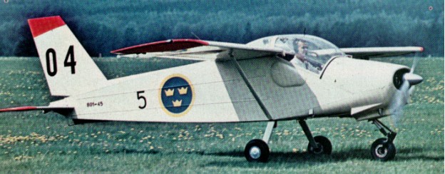
MFI had then been de¬veloping the MFI¬ 15A when Saab acquired Malmö Flygindustri (MFI) in 1968. The airplane made its maiden flight on 11 July 1969. As then flown it was powered by a 119kW Avco Lycoming IO-320-B2 flat-four engine and had a conventional low-set tailplane, but this was modified subsequently to T-tail configuration to minimise damage when operating from rough airfields. Later renamed Safari and then further developed into MFI-17 Supporter armed ground-support version. The plane was converted into an efficient weapons carrier by increasing the engine power and making some structural modifica¬tions – measures which greatly enhanced its military potential. The new version – the MFI-17 – made its first flight on 6 July 1972.

The prototype was flown on 26 February 1971 with a more powerful Avco Lycoming engine, which became the standard powerplant for the production version, which was re-designated Saab Safari. A braced shoulder-wing monoplane with fixed tricycle landing gear, available optionally with tailwheel landing gear, it provides side-by-side enclosed accommodation for two and has dual controls as standard.

A military version designated originally Saab-MFI 17 was flown on 6 July 1972 and differed from the Safari by being equipped more specifically for use as a military trainer, or for such duties as artillery observation, forward air control and liaison; this version was later named Saab Supporter.

The first purely military version, named the Supporter, was sold to Pakistan (where it was built under license as the Mushshak) in 1974. Further sales to Denmark, Norway and Zambia followed. A civilian version named the Safari was also sold to countries including Norway, Sierra Leone and Ethiopia. Counting both versions, more than 200 of the aircraft were built.
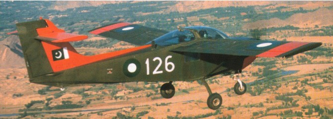
Pakistan Aeronautical Complex Super Mushshak

Licence production of the Saab MFI-17 Supporter two/three-seat piston-engined trainer and liaison aircraft continued at Kamra for the Pakistan Air Force and Army in 1987 by the Pakistan Aeronautical Complex, as the Mushshak.

Two MFI-17Bs were shipped to the PAF Academy in September 1974 for evaluation by trainer pilots and the Pakistan Army signed a contract with Saab in June 1974 to acquire five MFI-17B Supporters along with supply kits. The contract was signed to supercede the obsolete Howard L-19 trainer aircraft. A licence agreement was also obtained to build an indigenous aircraft based on the MFI-17B.

Assembly of Swedish-made kits began in 1976, but complete aircraft are manufactured in Pakistan using imported raw materials, engines, propellers, and avionics equipment. Licence-production of this aircraft was started in Pakistan during 1976, initially from kits supplied by Saab, but there has been a gradual change to indigenous manufacture from raw materials. Designated Mushshak in Pakistan, more than 150 have been built.
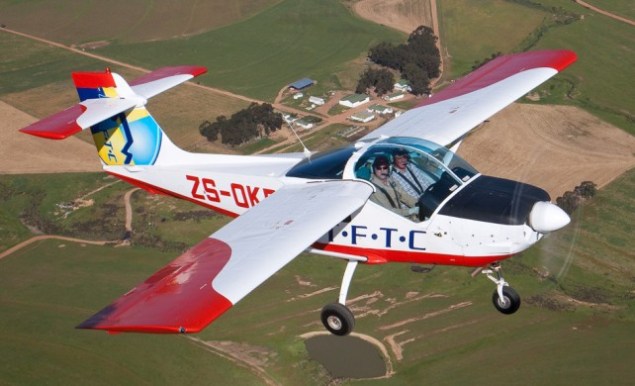
Upon taking the required suggestions from the Academy, the PAC started the development of MFI-17 Mushshak in June 1975 at its facility in Kamra, Pakistan. Saab ceased the supporter aircraft parts supply in 1982. The maiden MFI-17 Mushshak production aircraft was introduced in December 1983. The aircraft has been accredited by the Pakistan Civil Aviation Authority, and has obtained Type Acceptance certification from the South African Civil Aviation Authority.

The MFI-17 features two integral fuel tanks that carry 48gal of fuel. It also houses an electrical fuel pump for emergency missions. The aircraft is fitted with a Bendix fuel injection system, dual flight control systems, tricycle type landing gear, electrical trim, rudder pedals, ailerons and environmental control system.

It boasts a large luggage compartment on the rear side of the cockpit, which can be easily accessed through a door on the port side of the fuselage.

The glass cockpit of the Mushshak accommodates two crew members, a student pilot and an instructor. It is fitted with two adjustable seats integrated with lockable inertia reels, and there is an option for a third seat on the rear side. The round glass canopy offers clear visibility to the crew. An Enviro R-134 air conditioning system maintains constant temperature in the cockpit.

The cockpit is equipped with UHF radios, GPS, a voice-over recorder, automatic direction finder, rate of climb indicator, attitude heading reference system and an information friend or foe transponder.

The aircraft comprises six hardpoints. It is armed with two 7.62mm cannons, two 75mm unguided rocket pods, four 68mm unguided rocket pods and six anti-tank missiles.
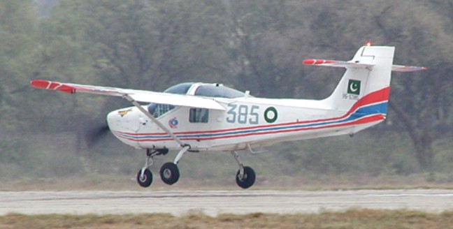
The Mushshak is powered by an AEIO-360A1B6 horizontally opposed four-cylinder piston aircraft engine, which generates 149kW of output power. The engine is designed and manufactured by Textron Lycoming. It is a fuel injected engine driven by two bladed constant speed hartzell propeller made up of aluminium.

The time between overhauls of the engine is 2,000 hours.

Orders of the MFI-17 include: the Egyptian Air Force (54), the Islamic Republic of Iran Air Force (25), the Royal Air Force of Oman (Eight), the Pakistan Air Force (149), the Royal Saudi Air Force (20) and the Syrian Air Force (Six).

The Danish airforce chose in 1974 Saab Supporter as their new trainer.
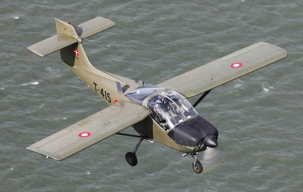
The MFI-17 was designed to train pilots of the PAF Academy located at Risalpur. The aircraft is fitted with a blind flying screen allowing for instrument flying missions. It was designed to meet the US FAR23 certification standards in utility and aerobatics classes.

The Mushshak was designed to operate on rough airfields even in adverse weather conditions. It can execute a wide range of ground attack missions including forward air control, border patrol, reconnaissance, artillery fire observation, liaison, camouflage review and transportation.

Some Mushshaks, promoted as very light strike and weapons training aircraft, served with the Iranian Revolutionary Guards.

Most of the Pakistan Aeronautical Complex Mushshak were upgraded to the more powerful Super Mushshak with a Lycoming 260 hp engine.
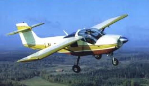
Variants:
Pakistan Aeronautical Complex MFI-395 Super Mushshak

Saab-Safari
Engine: 1 x Avco Lycoming IO-360-A1B6, 149kW / 200 hp
Max take-off weight: 1200 kg / 2646 lb
Loaded weight: 646 kg / 1424 lb
Wingspan: 8.85 m / 29 ft 0 in
Length: 7.0 m / 22 ft 11 in
Height: 2.6 m / 9 ft 6 in
Wing area: 11.9 sq.m / 128.09 sq ft
Max. speed: 235 km/h / 146 mph
Cruising speed: 208 km/h (129 mph)
Landing speed: 90 km/h (56 mph)
Range: 1050 km (650 miles)
Ceiling: 4100 m / 13450 ft

Pakistan Aeronautical Complex MFI-17 Mushshak
Engine: Textron Lycoming AEIO-360A1B6, 149kW
Propeller: two bladed constant speed hartzell
Climb rate: 5.2m/s
Maximum speed: 238km/h
Cruise speed: 210km/h
Stall speed: 100km/h
Range: 800km
Service ceiling: 4,100m
Endurance: 5 hr 10 min
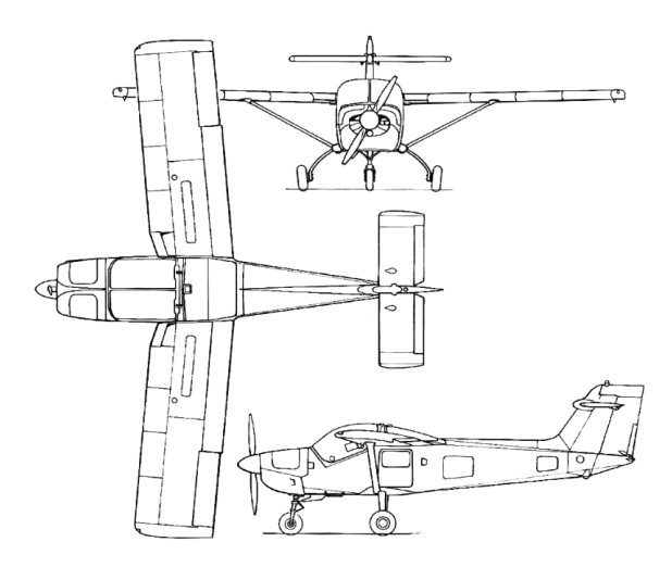
Saab-MFI 15/17 Safari-Supporter

SAAB

Svenska Aero
AB Svenska Järnvägsverkstäderna (ASJA)
Svenska Aeroplan Aktiebogalet (SAAB)

Svenska Aero, as a subsidiary of Heinkel, was taken over by AB Svenska Järnvägsverkstäderna (ASJA) in 1932.

The Bofors Company at Trollhattan formed in 1937 Svenska Aeroplan Aktiebogalet (SAAB). Following its merger in 1939 with the AB Svenska Jarnvagsverkstadernas Aeroplanavdelning (AJSA). In 1939 amalgamated with Aircraft Division of Svenska Jarnvagsverkstaderna and moved main establishment to Linkoping. From 1950 acquired other important facilities, including underground factory at Linkoping.

Built 82 Tiger Moth, 43 Hawker Hart, 11 NA-16-4M, FW-44, and Northrop 8A-5 under licence.

In 1945, in the hope of a lasting peace, the Company decided to scale down its production of military aircraft and to develop its civilian operations – a change in policy signified by the ap¬pearance of the Saab 90 Scandia airliner and the Saab 92 car.

Name changed to Saab Aktiebolag May 1965; Malmo Flygindustri became a subsidiary in 1967; in 1968 merged with Scania-Vabis group to became Saab-Scania. Current name Saab Group, comprising five main divisions: Saab AB, Saab Dynamics AB for guided weapons and electronics, Saab Training Systems AB, Saab Aircraft AB for marketing and supporting commercial aircraft, and Saab Combitech AB. Saab AB parent division established January 1997 to combine activities of previous Saab Military Aircraft, Saab Aircraft and Saab Service Partner, and develops and manufactures military and commercial aircraft within business units known as Gripen, General Military Aircraft, Future Products and Technology, Operations Commercial Aircraft, and Collaborative Programs.

First airplanes were license-built Junkers Ju 86K twin-engined bombers, Northrop-Douglas dive-bombers (Douglas 8A-1, similar to the US Army Air Corps’ A-17) and North American NA-16 trainers. First own-design production aircraft was Saab 17 dive-bomber of 1940, used widely and 60 delivered to Ethiopia from 1947. Saab 18 was twin-engined bomber of 1942, some late examples of which had ejection seats. Saab 21A of 1943 was piston-engined single-seat fighter, and 21-R was jet development of the same aircraft. Saab 29 was the so-called “flying barrel” swept-wing jet fighter, in production until 1956, while Saab 32 Lansen of 1952 was swept-wing fighter/attack/reconnaissance two-seater. Saab 35 Draken “double-delta” fighter appeared in 1955, and a squadron remained active as interceptors until 1999. Saab 105 of 1963, a twin-jet light side-by-side two-seater armed multipurpose aircraft, still in use as a trainer in 1999; Swedish Air Force aircraft have just undergone an upgrade with new engines and thus redesignated Sk 60W. Saab 37 Viggen multirole combat aircraft, first flown February 1967, has foreplane and delta wings, and with its STOL capability remains a very potent weapon system. Produced for service between 1971 and 1990, it has been continuously upgraded; redelivered in latest upgraded form 1998 for continued service in JA 37 interceptor and AJS 37 attack/interceptor/maritime-reconnaissance variants. Latest combat aircraft is Saab AB Gripen JAS 39 Gripen, first flown December 1988 and taken into Swedish Air Force service from 1996. Grippen is the world’s first combat aircraft of the new-generation type and the first to combine the roles of interceptor, attack, and reconnaissance in a single aircraft (all as primary roles) by the adoption of push-button control to select the required function in the computer programs of the totally integrated avionics suite.

Civil types have included Saab 90 Scandia twin-engined 32-passenger transport (first flown November 1946); Saab 91 Safir all-metal 3/4-seater (first flown November 1945); two/three-seat high-wing Safari (first flown in July 1969) and its military Supporter development (first flown 1972). In production until 1999 has been the Saab 340 turboprop regional transport (first flown January 1983, and finally produced in 340B and BPIus variants with accommodation for up to 37 passengers) and the Saab 2000 50/58-seat turboprop regional airliner (first flown March 1992). Saab has also developed an airborne early warning and control variant of the 340B airliner as the S100B Argus (first flight of AEW&C prototype with overfuselage radar July 1994), plus a search-and-rescue variant for the Japanese Maritime Safety Agency as the SAR-200 (delivered 1997).

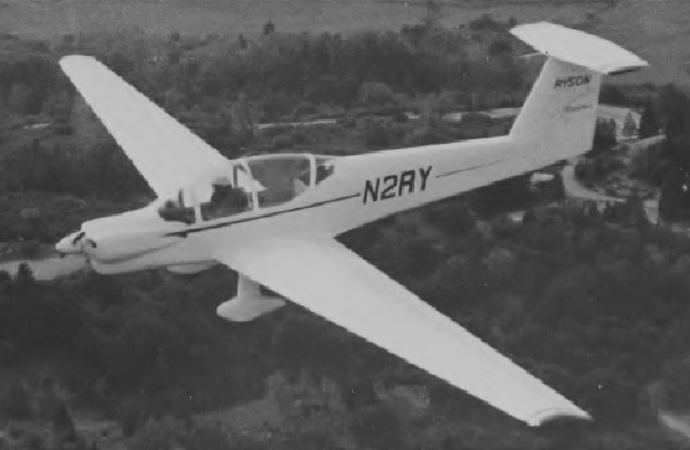
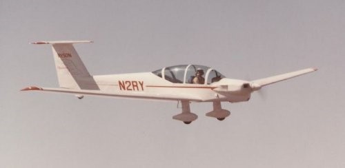
Ryson ST-100 Cloudster

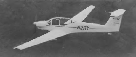
The ST-100 Cloudster tandem two-seater motor glider is believed to be the first American type in this category to be designed for production, and was created by the Ryson Aviation Corporation. A Pazmany designed self launching sailplane called the Cloudster, in mem¬ory of the original flagship of Ryan Airlines. The work Pazmany did designing the Cloudster’s landing gear led him to write the book “Landing Gear Design For Light Aircraft”.

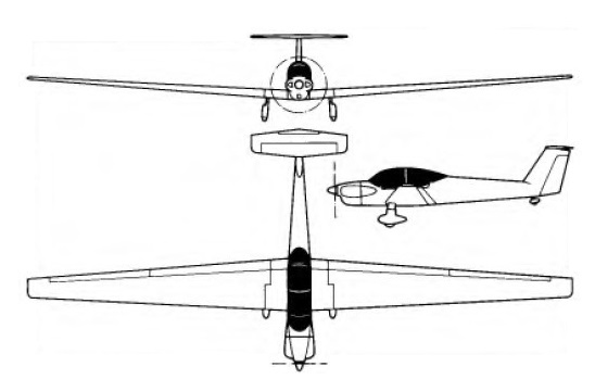
Design work started on 18 March 1974 as a cantilever low-wing monoplane of all-metal construction, with a T-tail, a fixed spatted undercarriage and a conventional engine installation with a Continental O-200, and of all-metal construction. The wings are all-metal safe-life structures, with some fail-safe features, and have a single main spar located at the 40% chord line, the point of maximum thickness, and an auxiliary spar at 80% chord; dihedral is 4°. Both ailerons and trailing edge flaps are of aluminium with a foam core, the flaps being electrically-operated and can be lowered to 72° when used as air brakes; the ailerons, like the flaps, can be raised 12° and they can be drooped 8° in conjunction with the flaps. After that, the flaps continue down to any desired position. No spoilers or trim tabs are fitted, and the wings can be folded back alongside the fuselage, leading edges down, for hangarage or transportation. The fuselage is a semi-monocoque structure with extruded aluminium longerons, and sheet metal frames, bulkheads and skinning. The pilots sit in tandem under a one-piece Plexiglas canopy that opens sideways to starboard; there is baggage space aft of the rear seat, and the rear occupant has flight controls but not an instrument panel, as he can see the instruments over the front pilot’s shoulders. Both seats are designed to accommodate parachutes, and the cockpit is heated and ventilated. The cantilever T-tail has a sweptback fin and rudder, a fixed-incidence tailplane and a one-piece balanced elevator. The rudder and elevator are aluminium-covered, with sheet metal and foam ribs, and the elevator tips can be removed when the aircraft is being transported; the elevator has an anti-servo and trim tab. A conventional fixed tailwheel landing gear is featured, with streamlined glassfibre fairings on the main gear legs, main wheels and tailwheel, which is steerable. The main wheels have Cleveland hydraulic disc brakes and Ryson oleo-pneumatic shock absorbers. Powerplant is a 100hp Continental 0-200-A ‘flat four’ engine driving a two-blade three-position Hoffman HO-V-62 feathering propeller with composite blades. There are two integral fuel tanks in the wing centre section leading edges with a total capacity of 32 US gallons (26.6 Imp gallons.)

Construction of the prototype, registered N2RY, began on 11 July 1974; it made its first flight on 21 December 1976 in the hands of test pilot Ray Cote.

The ST-100 is designed to be aerobatic and to meet the FAR Part 23 gust load requirements. It can also be used as an aero-tow aircraft for unpowered sailplanes. It has towed a Schweizer SGS 1-26 single-seater to 13,000ft with an initial climb rate of 450ft/min and, with two people aboard, it has also towed a Schweizer SGS 2-33 with two occupants at an initial rate of climb of about 400ft/min.

In the summer of 1977 Ray Cote made a notable economy-record flight in the ST-100 from El Mirage, California, to the EAA display at Oshkosh, Wisconsin, covering the 1,676 miles on 28 of the 32 available US gallons of fuel in 18 hours of soaring flight and 13 hours of powered flight. This was followed by a 4,300 mile flight around the perimeter of the United States. Only 20-percent power is required to keep the Cloudster in level flight. As a touring airplane, it cruises at 135 mph (75-percent power) using just 6 gph to yield a range of 690 miles. At lower power settings, the range can be greatly increased.

Production of the ST-100 by a licensee was planned when FAA type certification was awarded.

Engine: Continental O-200, 74.5 kW / 100 hp
Span: 57 ft 8 in / 17.58 m
Length: 25 ft 6.5 in / 7.78 m
Height: 5 ft 10 in / 1.78 m
Wingarea: 213.0 sq.ft / 19.79 sq.m
Aspect ratio: 15.61
Airfoil: Wortmann FX 67-170/17
Empty weight: 1,212 lb / 550 kg
Max weight: 1,650 lb / 748 kg
Water ballast: None
Max wing loading 7.74 lb/sq ft / 37.8 kg/sq.m
Max speed at sea level: 150 mph / 130 kt / 241 km/h
Max cruising speed: 135 mph
Stalling speed 69 km/h / 37 kt
Min sinking speed: 2.93 ft/sec / 0.89 m/sec
Best glide ratio: 28:1
T-O run: 570ft / 174m
Take-off run to 50ft: 950 ft
Max rate of climb at S/L: 895 fpm / 273 m/min
Range 595 nm / 1,103 km
Range with max fuel: 900 miles

Ryan 410

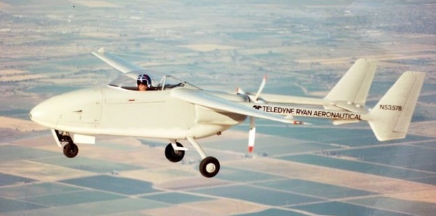
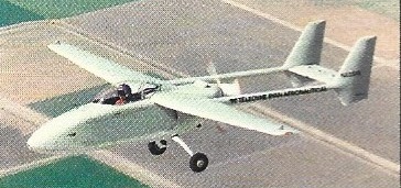
The Teledyne Ryan Model 410 was a surveillance UAV designed in the United States in the late 1980s. In configuration, it was a high-wing cantilever monoplane with twin tails carried on booms and linked by a common horizontal stabilizer. The engine was mounted pusher-fashion at the rear of the fuselage, between the booms. The nosewheel of the tricycle undercarriage was retractable. Construction throughout was of composite materials.

The Model 410 was Ladislao Pazmany’s last design before he quit Ryan. First flying on 27 May 1988, the sole prototype entered its flight test phase at Holtville, Calif, in October 1987. It was converted to manned operation for safety reasons, and completed its manned flight tests early in June 1988. It retained this configuration for the whole of the testing and development phase.

In 1993, the Model 410 was submitted to the UAV Joint Projects Office in response to an RFP for a Tier II system. In January 1994, the contract was awarded to General Atomics for what would eventually become the RQ-1 Predator.

Nothing is known about its fate or current whereabouts of the sole prototype, N53578, but it was deregistered. According to a Northrop Grumman employee, the Model 410 eventually proved overweight.

Powerplant: 1 × Lycoming TIO-320-C1B , 160 hp (120 kW)
Wingspan: 31 ft 0 in (9.45 m)
Empty weight: 1,450 lb (657.7 kg)
Capacity: 300 lb (140 kg) sensor payload carried in internal bay
Range: 1,200 mi (1,931.2 km, 1,000 nmi)
Endurance: 16 hours

Ryan VZ-11 / XV-5 Vertifan

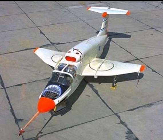
Developed with possible Army operational applications in view, the Ryan VZ 11 uses a totally different concept to obtain VTOL performance. The outcome of several years’ work on lift fans by General Electric Corporation, the VZ 11 derives its vertical lift from two ducted fans, one in each wing.

Unlike other ducted fans, above the General Electric version is powered by the jet exhaust from a turbojet engine which is directed on to turbine blades at the tips of the fan blades.

The VZ 11 layout has two 2,658 lb.s.t. General Electric J85 GE 5 turbojets in the fuselage, fed by a dorsal intake over the two seat cabin. For vertical operations, the fans are powered, together with a third fan in the nose which provides a small lift increment but is primarily for pitch control. For roll control, the thrust developed by the wing fans can be varied differentially by means of ‘butterfly’ doors over the inlets. Louvres under the outlets provide yaw control.

Once the VZ 11 is airborne, the louvres are moved to deflect the fan flow rearwards. This gives the aircraft a forward thrust component. As speed builds up the undercarriage is retracted. At about 120 knots, the wings provide sufficient lift to sustain flight and the exhaust flow from the two engines is then switched from the fans to direct propulsion nozzles. The butterfly doors and louvres close over the fan ducts and the aircraft continues as a conventional jet propelled type.

Two prototypes of the VZ 11 were ordered from Ryan in November 1961 as part of a U.S. Army research contract to investigate lift fans which was placed with General Electric. The designation was changed to VZ-5A in July 1962 and flight trials began in 1963. The XV-5 first flew in May 1964.

Ryan XV-5A Article

Republic Aviation joined GE and Ryan in XV-5A development and was directing flight tests at Edwards AFB in 1964. Republic would share in building additional prototypes if the craft met Army and DoD expectations.

XV-5A
Engines: 2 x 1200kg General Electric J85-GE-5
Max take-off weight: 7690 kg / 16954 lb
Empty weight: 5450 kg / 12015 lb
Wingspan: 9.25 m / 30 ft 4 in
Length: 13.75 m / 45 ft 1 in
Height: 4.5 m / 15 ft 9 in
Max. speed: 880 km/h / 547 mph
Ceiling: 12200 m / 40050 ft
Range: 1600 km / 994 miles

Ryan X-13 Vertijet

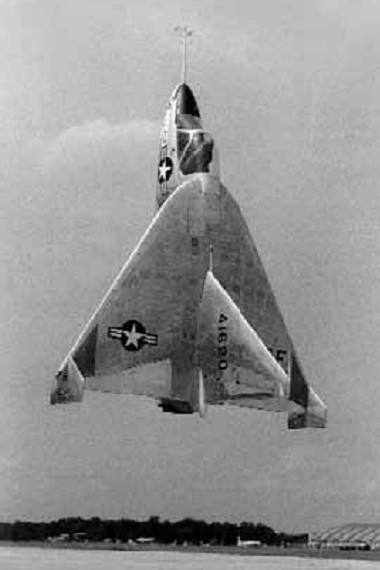
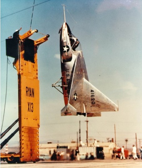
The X-13 was designed to explore the feasibility of building a pure-jet vertical takeoff and landing (VTOL) fighter aircraft. Secondary purposes included validating several Ryan designed VTOL control system concepts.

Ryan produced the X-13 Vertijet and XV-5 VTOL aircraft for the USAF. The X-13 was a ‘tail-sitter in the mould of the Convair XFY-1 and Lockheed XFV-1, though in this instance configured as a pure research type powered by a single 10,000-lb (4536-kg) Rolls-Royce Avon turbojet. The aeroplane first flew in conventional mode with temporary wheeled landing gear on 10 December 1955, and in ‘tail-sitter’ mode during May 1956.

The seat tilted forward 45 degrees to give the pilot a more comfortable position during vertical flight. Many early flights were made with no canopy. As first built, the X-13 had a huge fin, its height nearly as great as the wingspan. This was shortened during later testing.

The success and efficiency of the X-13 flight test program provided a significant amount of data to the designers of subsequent VTOL aircraft designs. The X-13s proved that vertical flight, on jet thrust alone, was both technically feasible and practical. The ease with which the aircraft routinely transitioned from vertical to horizontal attitude, and back again, left little question as to the flexibility and operational utility of such flight modes.

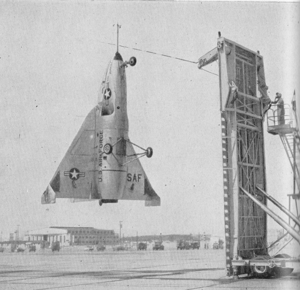
The delta-winged X-13 used a unique landing method, involving a special trailer, a hook and a striped pole. To land the pilot had to approach the trailer’s vertical base board without being able to see it. A pole marked with gradations protruded from the board and the pilot had to use this to judge his ‘altitude’ from the landing wire. In one demonstration at the Pentagon, the X-13 flew from its trailer, crossed the Potomac River, destroyed a rose garden with its thrust and landed in a net. Although this impressed the top brass, further funding was not forthcoming and the project petered out.

The last flight was made on 30 July 1957.
Fastest Flight: 483 mph (approx)
Highest Flight: 10,000 feet (approx)

Both X-13s survived their test program. The first aircraft is on loan from the National Air and Space
Museum to the San Diego Aerospace Museum in California. The second aircraft is on display at the Air
Force Museum in Dayton, Ohio.

Gallery

Engine: 1 x 4540kg Rolls-Royce Avon RA.28-49 turbojet
Max take-off weight: 3317 kg / 7313 lb
Wingspan: 6.40 m / 21 ft 0 in
Length: 7.13 m / 23 ft 5 in
Height: 4.60 m / 15 ft 1 in
Max. speed: 777 km/h / 483 mph

Ryan 92 / VZ-3 Vertiplane

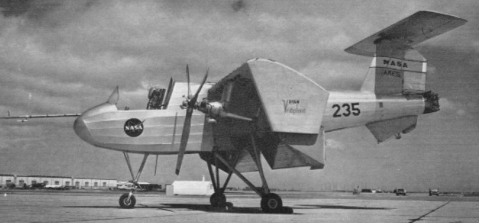
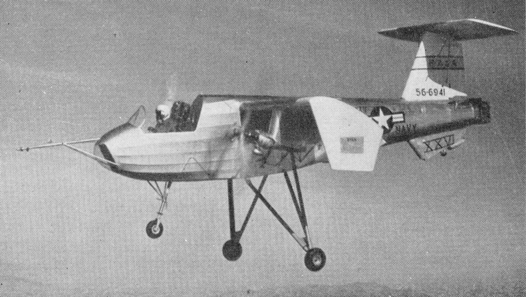
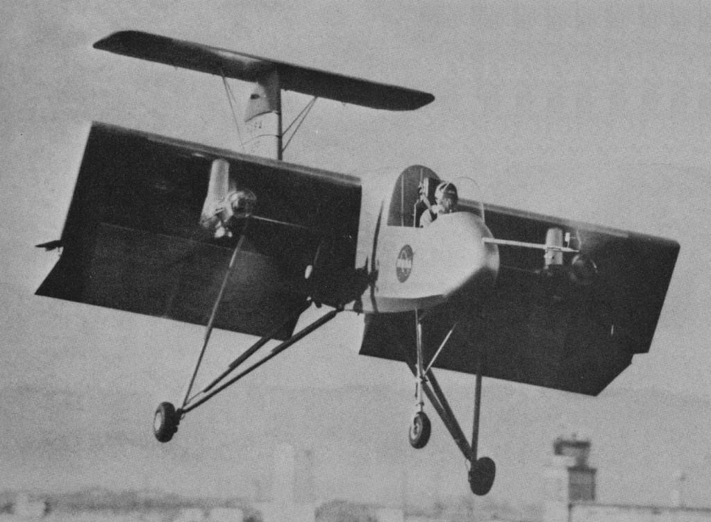
Ordered by the Army in 1956, the VZ 3 or Ryan Model 92 Vertiplane makes use of the deflected slipstream principle which was first proposed in the U.S. as early as 1921 by Dr. Albert F. Zahm. The principle consists of using a conventional wing and propellers for cruising flight and having large flaps on the wing trailing edge which, when extended, deflect the propeller slipstream down¬ward to obtain vertical lift.

The VZ 3 is basically a high wing monoplane with a 1,000 hp Lycoming T53 L 1 turboshaft engine in the fuselage driving two 9 ft. diameter slow running propellers. The wing tips were turned down to prevent spanwise flow and power loss when the flaps were down. For control at low, speeds, engine exhaust was directed to a swivel nozzle at the end of the fuselage, giving pitch and yaw control; roll control came from differential pitch applied to the propellers.

Ryan test pilot Peter Girard made the first taxying trials of the VZ 3 (56 6941) on February 7th, 1958.

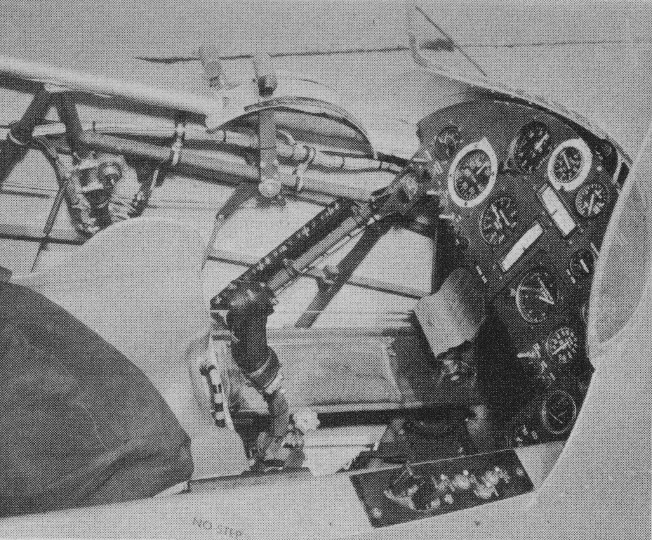
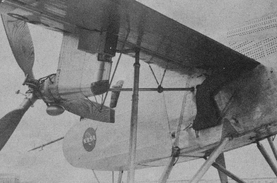
Subsequently, it spent three months in the full scale low speed wind tunnel at the N.A.S.A. Ames Laboratory at Moffet Field. At this stage it had a tail down undercarriage, but a nosewheel was added, as well as a large ventral fin, before the first flight was made on January 21st, 1959, at Moffet Field.

On the thirteenth test flight, on February 13th, 1959, the VZ 3 was damaged in a landing mishap caused by a malfunction in the propeller control system. Trials were resumed later in the summer and Ryan completed a test programme in which a speed range of 110 knots to 26 knots was covered, and flights were made up to 5,500 ft. For this second series of trials the cockpit canopy was removed.

In February 1960, after being handed over to NASA, the VZ 3 was almost completely de¬stroyed on a pilot familiarization flight. Operating outside the approved envelope for safe flight, it pitched up and completed most of a loop at 5,000 ft. The pilot ejected safely at 1,000 ft.

After it crashed in 1960 the VZ-3RY was rebuilt with lengthened nosewheel strut, 9 degree lower thrust axis and the LW-1 lightweight ejection seat. Utilising a deflected slipstream principle, the 785 shp Lycoming T53-L-1 turbine, located centrally in the fuselage, drives two wing-mounted Hartzell 3-bladed wood props whose slipstream covers the full wing span. For V/STOL and hover, double wing flaps are fully extended; for transition to horizontal flights, flaps are retracted as the plane picks up speed and the slipstream then flows horizontally.

70 degrees level flight with full flap, 29 mph

Conventional stick and rudder pedals controls actuate rudder, elevator, variable-incidence T-tailplane, and spoilers in the upper wing forward of the flaps, these replace the usual ailerons. Large wing tip end-plates provide structural support for the flaps and confine the slipstream.

Gas turbine tailpipe nozzles deflect Jetstream at right angles to eliminate forward thrust. Pitch and yaw control is achieved by shielding one side of the nozzle. For roll control ailerons actuate prop pitch control differentially when flaps are extended.

After a complete rebuild, the VZ 3 was returned to NASA in 1961 and pilots Fred Drinkwater and Bob Innis began a programme to investigate its low speed handling characteristics. Several modifications were made at this time, since when the VZ 3 has been contributing valuable data for the development of other VTOL aeroplanes.

Engine: 1 x 785 shp Lycoming T53-L-1
Props: 2 x Hartzell 3-bladed wood
Span: 23 ft 5 in
Length: 27 ft 8 in
Height: 10 ft 8 in
Gross weight: 2925 lb