Vickers FB.26 Vampire

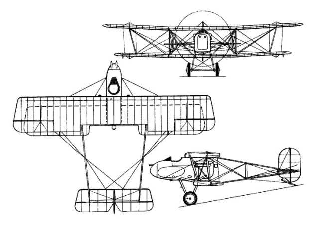
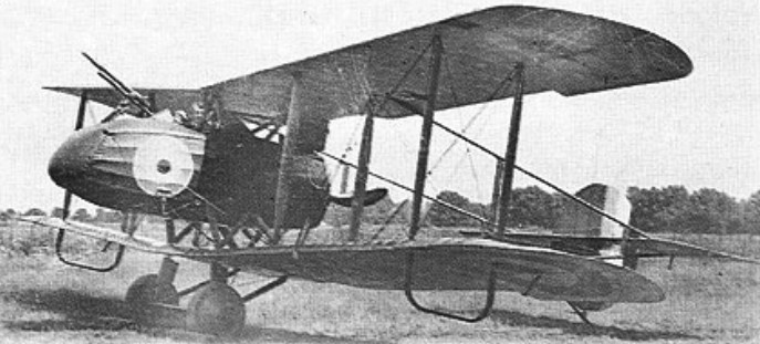
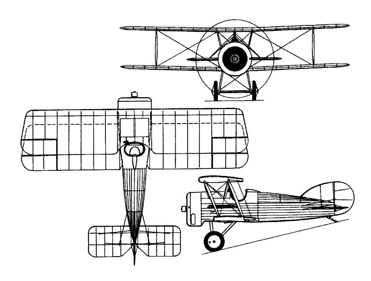
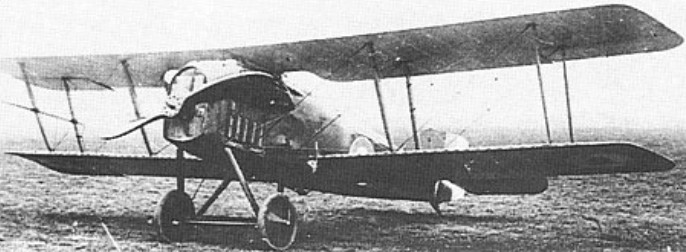
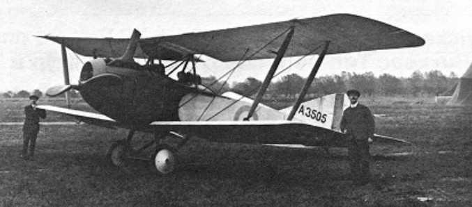
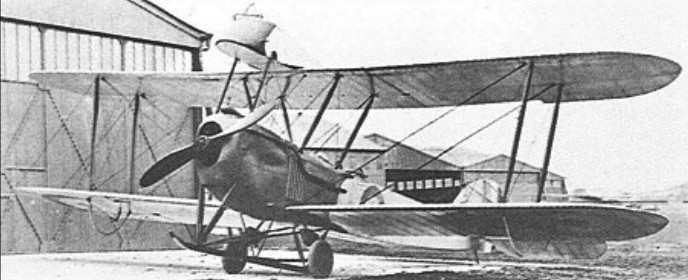
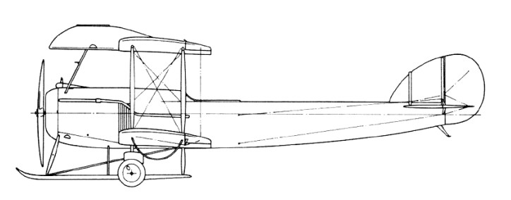
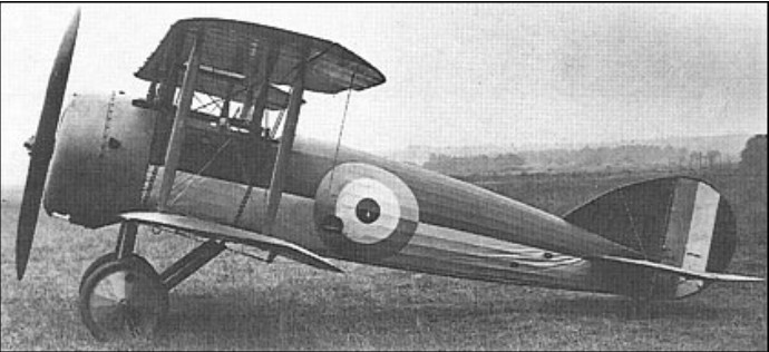
Curiously retrogressive in design when built in May 1917, the pusher fighter with boom-carried empennage being decidedly passe at that stage in Worid War I, the F.B.26 single-seat fighter had its nacelle attached directly to the upper wing. The original concept provided for a single 7.7mm Lewis gun, but an additional Lewis had been introduced by the time that the F.B.26 reached Martlesham Heath for official testing in July 1917.

Vickers FB.26 Vampire Article

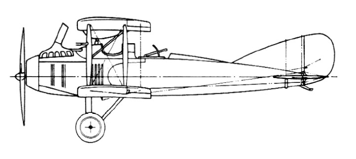
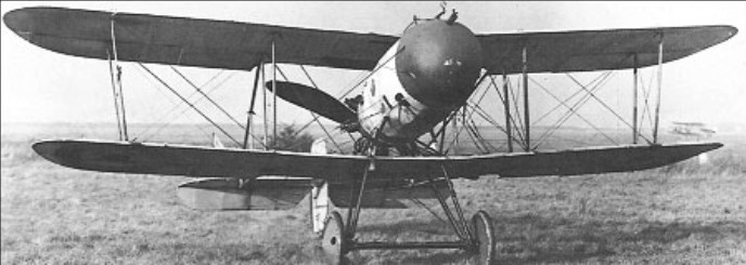
Power was provided by a 200hp Hispano-Suiza engine, but inadequate cooling led to the original single flat radiator being replaced by two separate radiator blocks. On 25 August 1917, the prototype was spun into the ground by Vickers’ test pilot Harold Barnwell. Nonetheless, a month later, on 19 September, a contract was placed for six examples of a modified version of the F.B.26. The wing structure was completely revised, radiator blocks were attached to the nacelle sides and a larger vertical tail was introduced. Interest in the F.B.26 centred on its potential as a Home Defence fighter, and it was proposed that armament would consist of two Lewis guns coupled with an Aldis sight and capable of several degrees of elevation and depression. However, in order to obtain greater firepower, the nacelle of the F.B.26 was modified to permit installation of an Eeman three-gun universal mounting. The first two F.B.26s had the trio of Lewis guns fixed to fire horizontally, but it was intended that the next four aircraft would have a modified Eeman mounting capable of 45° of elevation.

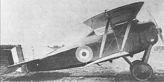
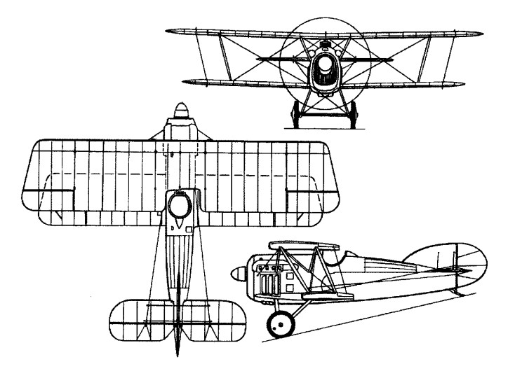
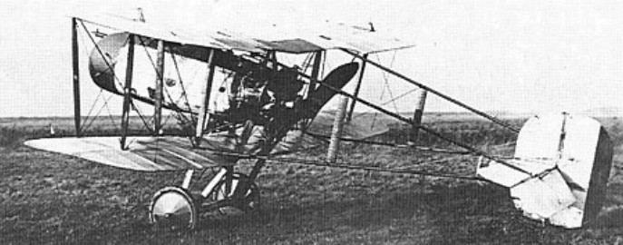
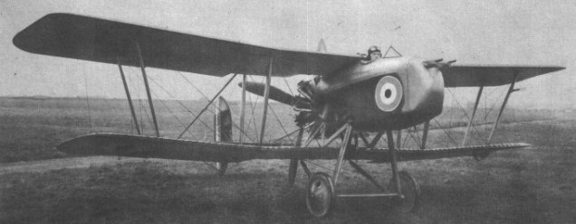
The first of the modified F.B.26s was flown in December 1917 with a 200hp Hispano-Suiza engine. After testing at Martlesham Heath, this aircraft was assigned to No 141 Sqn in February 1918 for service evaluation. It was concluded that the F.B.26 was unsuited for Home Defence duties and work on the incomplete machines was halted, although the second and third examples had been completed and flown meanwhile. As the basic design was considered to possess potential in the close air support role, the second of the modified F.B.26s was fitted with a redesigned nacelle incorporating armour protection for the pilot and a 230 hp Bentley B.R.2 nine-cylinder rotary. This armoured “trench-strafer” was assigned the designation F.B.26A, and, under the official nomenclature scheme introduced in the spring of 1918, became the Vampire II, the F.B.26 being the Vampire I. In the event, the Vampire II had still to be completed by the end of June 1918, and thus came too late on the wartime scene.

Max take-off weight: 921 kg / 2030 lb
Empty weight: 667 kg / 1470 lb
Wingspan: 9.63 m / 32 ft 7 in
Length: 7.14 m / 23 ft 5 in
Height: 2.87 m / 9 ft 5 in
Wing area: 24.80 sq.m / 266.94 sq ft
Max. speed: 195 km/h / 121 mph
Ceiling: 6860 m / 22500 ft

Vickers F.B.26 Vampire

Vickers FB.25

Derived from the abortive F.B.23 design intended as a successor to the F.B.9, the F.B.25 two-seat night fighter was conceived to fulfil the same requirement as the Royal Aircraft Factory’s N.E.1. Completed in the early spring of 1917, the F.B.25 carried its two crew members in staggered side-by-side seats, the gunner being positioned ahead and to starboard. Like the N.E.1, the F.B.25 was intended to carry the Vickers-built Crayford rocket gun with which it was supposed to attack hostile airships, and a small searchlight was originally to have been mounted in the extreme nose of the nacelle. The intention was to power the F.B.25 with the 200hp Hispano-Suiza eight-cylinder water-cooled engine, and in order to minimise the risk of the aircraft turning over during a nocturnal landing, it was proposed to provide a nosewheel. In the event, non-availability of a 200hp unit dictated installation of a 150hp Hispano-Suiza, and neither searchlight nor nosewheel was fitted. A two-bay unstaggered equi-span biplane with tailbooms converging in elevation to meet at the rear spar of the tailplane, the F.B.25 carried its unusually wide nacelle at mid wing-gap. As well as the Crayford rocket gun, an interesting feature was the oleo-pneumatic undercarriage. Flight testing revealed poor characteristics, and when sent to Martlesham Heath in May 1917 (where it was eventually to crash), the official reports were singularly unflattering, dismissing the F.B.25 as wholly unsuited for night fighting.

Max take-off weight: 1113 kg / 2454 lb
Empty weight: 729 kg / 1607 lb
Wingspan: 12.65 m / 42 ft 6 in
Length: 8.56 m / 28 ft 1 in
Height: 3.30 m / 11 ft 10 in
Wing area: 46.45 sq.m / 499.98 sq ft
Max. speed: 138 km/h / 86 mph
Ceiling: 3355 m / 11000 ft

Vickers FB.24

A two-seat fighter-reconnaissance aircraft, the F.B.24 was yet another Vickers aircraft originally designed for the ill-fated and Vickers-sponsored Hart radial engine. The prototype was completed in December 1916, but unavailability of the Hart engine resulted in its modification to accept the 150hp Hispano-Suiza water-cooled engine as the F.B.24A, and the second airframe, the F.B.24B, being similarly powered. An unequal-span two-bay biplane, the F.B.24 had an armament of one fixed synchronised Vickers gun and one Lewis on a Scarff ring mounting. Both F.B.24A and 24B were re-engined with the 200hp Hispano-Suiza with which they were redesignated as F.B.24Ds. Similar in general configuration was the F.B.24C, which was powered by a 275hp Lorraine-Dietrich 8Bd water-cooled eight-cylinder Vee-type engine and armed with two synchronised Vickers guns, provision being made for emergency dual control in the gunner’s cockpit. The F.B.24C and D both possessed good performance, but the limited view offered from the pilot’s cockpit was considered unacceptable. Consequently, the Vickers team revised the basic design by lowering the upper wing so that it was attached directly to the upper longerons, the front cockpit being situated between the wing spars. With this change, the aircraft was de signated F.B.24E and power was provided by a 200hp Hispano-Suiza. This same configuration was adopted for yet a further version of the design, the F.B.24G, which was a larger aircraft than its predecessors, with two-bay wings of equal span and chord and a 375hp Lorraine-Dietrich 12-cylinder Vee-type engine. The F.B.24G was built in France by the Darracq concern, but it did not fly until 26 May 1919, and its performance and fate have gone unrecorded.

F.B.24D
Empty weight: 739 kg / 1629 lb
Wingspan: 10.82 m / 36 ft 6 in
Length: 7.92 m / 26 ft 0 in
Wing area: 31.59 sq.m / 340.03 sq ft
Max. speed: 190 km/h / 118 mph

Vickers F.B.24

Vickers FB.19

Designed in 1916 by G H Challenger and flown for the first time in August of that year, the F.B.19 was a single-bay unstaggered equi-span biplane with a single 7.7mm Vickers gun mounted on the port side of the fuselage and a 100hp Gnome Monosoupape engine. Ordered by the War Office for the RFC, the series version was powered by either the Gnome or the 110hp Le Rhone. Some 50 F.B.19s were built, and, late in 1916, a batch of six was sent to France where, after operational evaluation, the fighter was deemed un-suited for the fighting conditions then evolving. At this time, some of the F.B.19s were delivered to the Russian government following demonstrations in Petrograd, Moscow, Kiev and Tiflis, but several were still in their crates on the docks at Archangel at the commencement of the Bolshevik revolution. These aircraft were destroyed by the Royal Navy, but a few others assembled prior to the Navy’s action were flown in Bolshevik service. A modified version, the F.B.19 Mk II, was developed with wing stagger and either the Le Rhone or Clerget 110hp rotary. Only 12 Mk IIs were built and several of these were included in a batch of 12 F.B.19s sent to the Middle Eastern theatres of war. These were flown in Palestine and Macedonia from June 1917, but no squadron used the type exclusively and it was not well liked.

F.B.19
Engine: 1 x Gnome Monosoupape, 75kW
Max take-off weight: 670 kg / 1477 lb
Empty weight: 405 kg / 893 lb
Wingspan: 7.31 m / 24 ft 0 in
Length: 5.54 m / 18 ft 2 in
Height: 2.51 m / 8 ft 3 in
Wing area: 19.97 sq.m / 214.96 sq ft
Max. speed: 158 km/h / 98 mph
Ceiling: 5180 m / 17000 ft

Vickers F.B.19

Vickers FB.16

Conceived, like the F.B.12, to utilise the 150hp Hart engine, the F.B.16 was designed by Rex K Pierson. Completed and flown in the summer of 1916, it was a single-bay staggered biplane with a fuselage faired out fully to an elliptical cross section, the Hart engine being partly cowled, and armament consisting of a single centrally-mounted synchronised 7.7mm Vickers gun. During the course of testing, the part-cowling was removed from the engine to improve cooling, the decking aft of the cockpit was cut down and new vertical tail surfaces were fitted. With the ending of Hart engine development, the basic F.B.16 underwent very considerable redesign, reappearing as the F.B.16A with a 150hp Hispano-Suiza water-cooled Vee-eight engine. This aircraft was destroyed in a crash on 20 December 1916, but a second identical aircraft was completed in the following month. The F.B.16A had flat fuselage sides and the single synchronised Vickers gun was supplemented by a Lewis mounted above the centre section.
After receiving favourable reports during Martlesham Heath trials, it was re-engined with a 200hp Hispano-Suiza engine as the F.B.16D, a wider-chord wing being fitted, with both gap and stagger increased, and a larger vertical tail fitted. The synchronised Vickers gun was replaced by a Lewis firing through the hollow propeller shaft. Because large contracts had been placed for the contemporary S.E.5a, particularly with Vickers, and because Martlesham Heath evaluation contained numerous design criticisms of which rectification would have been time consuming, the F.B.16D was not ordered into production.
Nonetheless, work on a further development, the F.B.16E, continued, this having a 275hp Lorraine-Dietrich 8Bd eight-cylinder Vee-type water-cooled engine and two 7.7mm synchronised Vickers guns totally enclosed in elongated blisters between the cylinder block fairings. The F.B.16E was tested at Villacoublay by the French authorities, encouraged by the manufacturer’s performance claims, including a speed of 220km/h at 3050m and the ability to climb to that altitude within 7.85 min. During Villacoublay trials, the F.B.16E allegedly returned performance figures unsurpassed by any of its contemporaries, but no production order was placed, and on 29 July 1918, the prototype crashed after its propeller disintegrated.

F.B.16D
Max take-off weight: 850 kg / 1874 lb
Empty weight: 624 kg / 1376 lb
Wingspan: 7.62 m / 25 ft 0 in
Length: 5.94 m / 20 ft 6 in
Height: 2.67 m / 9 ft 9 in
Wing area: 19.23 sq.m / 206.99 sq ft
Max. speed: 217 km/h / 135 mph
Ceiling: 5640 m / 18500 ft

Vickers F.B.16

Vickers FB.12

A compact two-bay biplane of pusher type, the F.B.12 was designed for the 150hp Hart static radial engine, in the development of which the Hart Engine Company was being assisted by Vickers.

With a single-seat nacelle faired out to a circular cross section and mounted in mid wing-gap, and tailbooms converging in side elevation to meet at the rear spar of the tailplane, the F.B.12 had a basic structure primarily of steel tube.

Vickers FB.12 Article

Unavailability of an airworthy Hart engine led to the first F.B.12 being fitted with an 80hp Le Rhone rotary, with which it flew in June 1916. Although underpowered, it demonstrated a creditable performance when tested at the Central Flying School in the following August. The Le Rhone was then replaced by a 100hp Gnome Monosoupape, and, subsequently, new wings of greater span were fitted – overall span being extended by 1.09m – with straight raked rather than elliptical tips. Redesignated F.B.12A, this aircraft was sent to France for operational evaluation in December 1916.

A further aircraft was built – by Wells Aviation of Chelsea – with the Hart engine as the F.B.12B. This was flown early in 1917, but promptly crashed, helping to seal the fate of the Hart radial. A contract for 50 aircraft powered by the Hart had, on 10 November 1916, been awarded Vickers, the intention being to fit the series aircraft with a new, wooden nacelle and enlarged vertical tail surfaces as the F.B.12C.

Production of the F.B.12C was sub-contracted to Wells Aviation, but with the loss of the F.B.12B, the Hart engine was abandoned. In the event, only 18 F.B.12C airframes were completed and these were fitted with a variety of engines, including the 110hp Le Rhone nine-cylinder rotary and the 100hp Anzani 10-cylinder radial.

Testing at Martlesham Heath in May 1917 revealed insufficient elevator control at low speeds, heavy lateral control and other problems. Furthermore, the gun (a 7.7mm Lewis) was considered to be badly positioned for changing ammunition drums. By this time, tractor fighters of superior performance were in RFC service and further development of the F.B.12 was therefore discontinued.

F.B.12C
Max take-off weight: 656 kg / 1446 lb
Empty weight: 420 kg / 926 lb
Wingspan: 9.02 m / 29 ft 7 in
Length: 6.65 m / 21 ft 10 in
Height: 2.62 m / 8 ft 7 in
Wing area: 22.02 sq.m / 237.02 sq ft
Max. speed: 140 km/h / 87 mph
Ceiling: 4420 m / 14500 ft

Vickers F.B.12

Vickers FB.11

Designed by Howard Flanders as an airship destroyer, for which purpose it had an elevated gunner’s station, or “fighting top”, mounted on the centre section of the upper wing, the F.B.11 flew in late November 1916. Carrying a crew of three, including two gunners each provided with a 7.7mm Lewis gun, the F.B.11 was powered by a 250hp Rolls-Royce Mk III 12-cylinder water-cooled engine – later to be named Eagle. The F.B.11 proved to be deficient in lateral control and the first prototype eventually crashed and was written off, a second example never being completed as, in the meantime, it had been realised that the entire concept of the large airship destroyer was fundamentally unsound.

Max take-off weight: 2238 kg / 4934 lb
Empty weight: 1515 kg / 3340 lb
Wingspan: 15.54 m / 51 ft 0 in
Length: 13.10 m / 43 ft 0 in
Height: 4.16 m / 14 ft 8 in
Wing area: 78.50 sq.m / 844.97 sq ft
Max. speed: 154 km/h / 96 mph
Ceiling: 3355 m / 11000 ft

Vickers F.B.11

Vickers FB.8

Although possessing a superficial resemblance to the F.B.7, the F.B.8, designed in the autumn of 1915 by Rex K Pierson, was a very much smaller, lightly-armed two-seat fighter carrying only a single 7.7mm Lewis gun as armament. Powered by two 100hp Gnome Monosoupape rotaries, the F.B.8 began flight testing in November 1915, and performance proved to be good. The gunner was accommodated in the extreme nose and the pilot was seated beneath the trailing edge of the upper wing. From the outset, it was obvious that the armament carried by the F.B.8 could equally well be accommodated by a smaller, single-engined aircraft, but it had been hoped that an appreciably higher performance could be obtained by doubling the power available. Insufficient attention had been paid to the drag of such an aircraft, however, and performance proved lower than had been anticipated. Furthermore, the aircraft was insufficiently manoeuvrable for fighting duties and was discontinued.

Max take-off weight: 1225 kg / 2701 lb
Empty weight: 835 kg / 1841 lb
Wingspan: 11.68 m / 38 ft 4 in
Length: 8.58 m / 28 ft 2 in
Height: 3.00 m / 10 ft 10 in
Wing area: 43.48 sq.m / 468.01 sq ft
Max. speed: 158 km/h / 98 mph
Ceiling: 4270 m / 14000 ft

Vickers F.B.8

Vickers ES.1

Early in 1915, Rex K Pierson was tasked with the redesign of the so-called Barnwell Bullet, an unarmed single-seat biplane designed as a private venture by Vickers’ then chief test pilot, Harold Barnwell. Assigned the designation E.S. (Experimental Scout) 1 and completed in August 1915, the redesigned aircraft was powered by a 100hp Gnome Monosoupape rotary and carried no armament. An equi-span single-bay unstaggered biplane, the E.S.1 was aerodynamically clean and possessed an excellent performance, but view for the pilot was extremely poor. An improved version was then developed, powered by the 110hp Clerget nine-cylinder rotary engine. This was assigned the official designation E.S.1 Mk II, although it was known to Vickers as the E.S.2. Two E.S.1 Mk IIs were built, one of these being fitted with a 7.7mm Vickers machine gun with Vickers-Challenger synchronising gear and sent to France in the summer of 1916 for operational trials with No 11 Sqn, RFC. The other E.S.1 Mk II was eventually similarly armed and tested with a 110hp Le Rhone rotary, while the original E.S.1, too, was fitted with the gun and synchronization gear, and was at one time included on the strength of an RFC Home Defence squadron (No 50). The official evaluation of the E.S.1 in both versions pronounced the aircraft tiring to fly and difficult to land, and no production was ordered. The E.S.1 did, however, serve as a basis for the design of the later F.B.19.

E.S.1 Mk II
Max take-off weight: 681 kg / 1501 lb
Empty weight: 445 kg / 981 lb
Wingspan: 7.43 m / 24 ft 5 in
Length: 6.17 m / 20 ft 3 in
Height: 2.34 m / 8 ft 8 in
Wing area: 19.97 sq.m / 214.96 sq ft
Max. speed: 180 km/h / 112 mph