The 1911 Bastier biplane was designed and built by Bastier in France.
Span: top 32’10” bottom 23′
Length: 31’2″
Weight: 992 lbs
Speed: 50 mph
The 1911 Bastier biplane was designed and built by Bastier in France.
Span: top 32’10” bottom 23′
Length: 31’2″
Weight: 992 lbs
Speed: 50 mph
The 1911 Barucki II biplane was designed and built by Eng.Barucki in Poland.
The 1911 Barucki I monoplane was designed and built by Eng.Barucki in Poland.
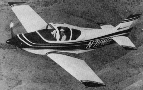
Wayne Barton of Northglenn, Colorado, began doodling his dream ship and the general outline of his dream ship began to take shape. Barton began at the bottom, sketching in plenty of ground clearance to swing a big prop and a stabilator. It need at least a Lycoming O-320 and a retractable trigear. The first few degrees of rotation of the primary retract handle break the over-center gear brace arms, and after about 10 degrees of travel, the springs change their action; instead of holding the gear locked, they begin to pull the gear up, with the springs providing 95 percent of the effort.
In retracting the nose leg, the steerable nosewheel linkage neutralises, and when you’re up and flying, kicking the rudder pedals only actuates the aerodynamic rudder. After about 120 degrees of travel, the retract handle locks into a socket, and a microswitch automatically causes a solenoid to, lock each gear into the full up position.
Going the other way, as when putting the gear down for landing, moving the down gear handle into its socket actuates a gear-locked indicator light on the panel when the fast few degrees of down handle rotation applies pressure to the gear over-center brace arms. Gear doors are attached to the legs and open or close automatically.when you raise or lower the gear.
The stabilator was designed with a 12-degree rotation capability around its single spar, which is built in two units, the right and left sides being joined with a splice tube which serves as an attach point for the counterweight. An antiservo unit gives the stick backpressure feel, and is also linked to the cockpit pitch-trim wheel. All linkage is hidden inside the fuselage and fin area.
Barton went to dual controls, with brakes on the left side only, and the mechanical flap handle was attached to the same pivot unit as the primary gear retract handle. A Cessna-type pitch trim wheel is located between the two seats, with an additional aileron trim hung on the forward face of the main spar near the pilot’s right knee.
Three fuel tanks are located inside thefuselage, with a 28 Usg fiberglass main tank aft of the passenger seats below the baggage compartment. An engine-driven fuel pump transfers fuel from the main to a pair of header tanks back of the firewall under the panel, holding a total of 14 gallons. From there the fuel is gravity-fed to the carburetor.
Barton used a Minicab wing of 24 feet 11-inch span and 110 sq.ft. area, fully cantilevered, with a 15 percent rib chord at the root. This provided adequate, depth to hide the gear when retracted. The chord depth tapers to 10 percent at the tips, with a uniform twist of two percent.
The Emeraude fuselage provided an ample cabin width of 42 inches, and a sliding bubble canopy provided easy access and good visibility. Retractable steps allow entry over the flaps at the wing root area on either side. These were a few extras that only added 20 pounds to Barton’s design empty weight of 1000 pounds.
Barton came in for under $8,000 in 1979 dollars, mainly by building everything from raw materials, except for a few ready-made essentials like the engine, wheels, nuts, bolts and gauges. Airframe construction was of sitka spruce; some hardwood for high shear stress points; plywood; chromoly 4130 tubing; and some aluminum alloys.
In building the fuselage, Barton used the standard right and left side frame construction method, the sides turned over on the work table and positioned properly for fitting the wing attach bulkhead, seat back bulkhead and fin spar. Cross braces were cut to fit, ply gussets added, and the fuselage turned right side up again, for adding turtle deck, fin.
Next came the nose gear well framing, firewall, stabilator and rudder, which had three ball-bearing hinges, with a conventional external rudder horn. No counterbalancing was required.
In building the Minicab wing, Barton beefed up the spar center sections to prov ide a 9G ultimate load factor for a 1200-pound airframe. The gap contour between flap/aileron and wing proper was modified for better aerodynamic efficiency, and the entire wing skinned with plywood. As for the gear, Barton says: 1t evolved as a sort of hybrid, part Beechcraft, part Mooney, part Barton.”
Internal compression springs were used for shock absorbing, together with an internal oil damping action using the same shaft with attached piston for rough-field operation,
The engine is enclosed in a conventional fiberglass cowling with the nose gear door hinged to the aft part of the cowl. Canopy framework is of wood construction with the acrylic plastic windows held in place with ordinary glazier’s points and silicon rubber.
To finish everything off Barton went to Dacron covering and Randolph’s dope.
In April 1975, Sylkie One, passed final FAA inspection, and her maiden flight was on May 2, 1975.
Engine: Lycoming O-320 / 150 hp.
Prop: Wood, fixed pitch, 72 in dia.
Wingspan: 24ft 11in.
Wing area: 110 sq.ft.
Fuselage length: 20ft 7in.
Height: 7ft 1in.
Empty wt: 1020 lbs.
Max wt: 1650 lbs.
Econ cruise: 10,000 ft 6.9 gph, 182 mph TAS.
Vmax (17,000ft): 234 mph TAS.
Stall: 48 mph IAS.
Climb: 1800 fpm.
Service ceiling: 19,000ft.
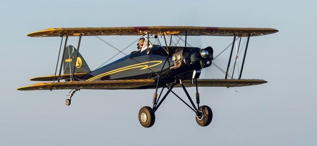
The Skyotë is a plans-built aircraft design dates back to the 1970s when it was created by Pete Bartoe. His goal was to create a plane that was affordable and easy to fly, with enough performance to be competitive at the International Aerobatic Club’s Intermediate level.
Bartoe met his design goals, and the delightful handling qualities of the Skyotë were praised by R.A. “Bob” Hoover in a flight report that appeared in the December 1976 issue of Sport Aviation.
The Skyotë uses a biplane planform, with a swept wing. It has a single seat, tube-and-fabric fuselage with an all-aluminum structure, and fabric-covered wings stressed for +9/-6 G. Weight and performance qualify it for the Light Sport category, and it uses a Continental O-200 engine.
The airplane is not a typical plans-built homebuilt. Bartoe did not design it with homebuilding in mind; his intention was factory production.
Because the goal was good aerobatic performance on minimum horsepower, each part is optimized for its purpose. As a result, parts are made from six gauges of aluminum, seven gauges of steel, and three gauges of stainless steel. The 7.2-degree wing sweep looks and performs great, but is hard to build. Brackets in the wings have left, right, top, and bottom positions, so one part can have four different bending configurations depending on what wing location you’re building. The mounting clips for the wing ribs have an acute angle on one side and an obtuse angle on the other side.
Although the Skyotë didn’t make it to production, Bartoe sold around 100 sets of plans. Twelve airplanes have been completed from the original plans, but about half of those were factory prototypes. The first, N8XX, first flying on 23 April 1976 powered by a 90hp Continental C-90F.
John Roberts was one of those people who ordered a set of plans. But when he received them, it didn’t take long to discover why only five builders had completed their airplanes after nearly 40 years—the drawings were incredibly complicated, and the skill level required was way beyond the ability of most potential builders.
Roberts decided to use modern technology to get his plane, Skyotë #88, into the air, as the Tech-Built Skyotë.
Knowing that Pete Bartoe had mathematically calculated all Skyotë dimensions to an accuracy of three decimal places for all three axes led John to see the combination of Skyotë plans and 3D CAD as a better way to have the Skyotë he wanted.
While learning Geomagic 3D CAD software, John selected parts from Bartoe’s drawings and created CAD models for each part. Over time, he ended up with more than 150 drawings depicting nearly 600 parts that needed to be fabricated for the Skyotë.
The software’s 3D modelling feature produces assembly drawings that are very easy to understand. By assembling the parts in “virtual space,” you can be sure that all of the parts will fit together correctly.
The CAD program also confirmed the accuracy of Bartoe’s original calculations. With a total of nearly 1000 pieces in the Skyotë and tens of thousands of holes, John discovered only one small error—a single hole was off about 1/32 inch. That discrepancy has been corrected.
To convert his .dfx files into parts a waterjet cutting process cut about 600 flat metal parts to make fittings for the wings and fuselage.
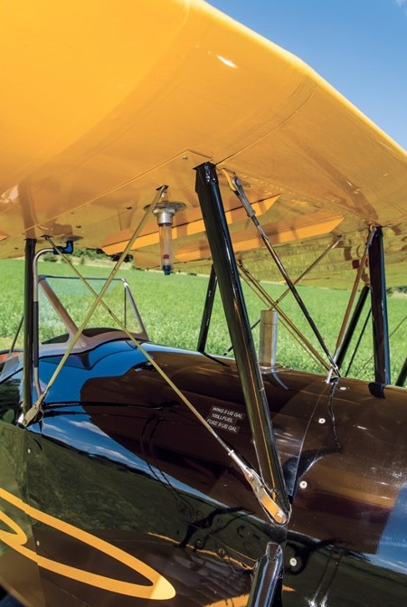
In the wings there are three compression struts between the front and rear spars, along with drag and anti-drag wires, and one tubular brace out at the tip.
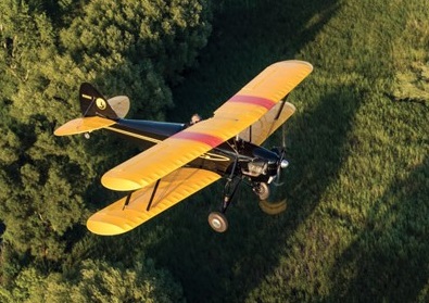
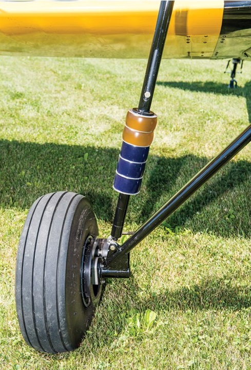
The fuselage is welded steel tube construction with fabric covering. The standard gear uses bungee shocks, and by all reports, it works just fine. A shock strut that uses urethane donuts with various amounts of stiffness for the Tech-Built Skyotë is simple to adjust the amount of bounce, and the donuts are unlikely to wear out.
Engine: Continental O-200, 100 hp
Prop: Catto 2-blade fixed pitch
Wingspan: 20 ft 0 in
Length: 16 ft 3 in
Empty weight: 656 lb
MTOW: 975 lb
Fuel capacity: 15 USG
Full fuel payload: 229 lb
Cruise: 90 kt
ROC: 1200 fpm
Landing speed: 40 kt
Stall: 38 kt
Takeoff roll: 300 ft
Landing distance: 550 ft
Load rating: +9 G/-6 G
Cabin width: 20.25 in
Seats: 1
Engine: 118hp Lycoming O-235-K2A
Wingspan: 20’0″
Length: 16’3″
Useful load: 297 lb
Max speed: 157 mph
Cruise: 112 mph
Stall: 44 mph
Range: 207 mi
Seats: 1
Jerry Morris has over 20,000 flight hours. He was an Air Force C-130 pilot, flew civilian charter for several years, and then was a captain for Delta Air Lines.
I had an opportunity to fly a Skyotë, and what a blast it was.
Climbing in was really not bad, even for an old guy like me. Left foot in the step on the fuse and swing your right leg up and over, and into the single seat. There is a very sturdy handhold conveniently placed in the center of the upper wing that really helps here. Sliding down in, the cockpit rails are tight, but once settled in, they barely rubbed on my shoulders, and it was really comfortable. The low windscreen proved to be very effective, and the visibility all around was open-cockpit superb. All the controls and switches were very accessible and required no stretching or reaching. Very nice.
The little Continental O-200 had already been run this day, so mags on, throttle cracked, mixture in, and crank away. A couple blades later it was up and running. Everything in the green and off I went.
Visibility was actually pretty good taxiing. Slight S-turning was all that was needed. Toe brakes were hardly needed, and the steering through the rudders was very effective but not twitchy. Runup is standard, and I was ready to go.
The Skyotë is a light plane and even with just 100 hp accelerated quickly. By the time I had the power all the way in, the tail was up and ready to fly. Directional control was not an issue, and I was off. Climbing at 70 brought a solid feel with not too high a pitch attitude and excellent visibility. Once out of the pattern, I went up to a higher altitude to play a little.
This thing turns on a dime. Rudder is required, but not much. I led with just a touch, then aileron, and around we went. Same for rolling out. After just a couple turns, it became second nature. It has very light controls, both roll and pitch, and fingertip pressure is all that’s needed to fly. It was easy to trim with the electric trim on the elevator, but there was not a lot of pitch change to trim out with speed changes.
Slow flight at 60 is easy. With power off and holding the nose up, I started feeling the burble in the low 40s. There was an easy break, and the times I stalled it, it wanted to break ever so slightly to the left. A touch of rudder with center stick, though, and I could keep it level. It was very docile.
Steep turns, wingovers, and hammers are all textbook simple and very honest. All the while I enjoyed the great visibility through the wings that seemed to be placed just right for seeing through.
Back to the pattern with my dancing shoes on. In typical carbureted fashion, carb heat on abeam the numbers. I used 70 on base, and once established on final back to 60 indicated. There’s pretty good drag, so with my usual picture, I carried a tad of power down final. Bleeding off over the numbers in the flare, I three-pointed it at just over 50 indicated. Directional control was great, and visibility just out the side of the cockpit was typical taildragger, with not much over the nose. Carb heat and power in, and off I went again.
Next I tried a wheel landing. Same pattern with just a tad of power to keep the speed up for the touchdown. John’s gear is forgiving and wheelies will be simple with just a few tries. Visibility is great with the tail up, and the rudder is very effective. I went up one more time to the final landing, which was basically a repeat of the first. It three-points very nicely and tracks true down the runway with minimal rudder required. Touching down around 50 produces a nice short landing roll, then back to the barn I went, wearing a big grin.
This little ship is a joy to fly, with fingertip controls that are well balanced. Stable in pitch and roll, it didn’t wander around while I was enjoying the view. And what a view! Flying wires and wings were everywhere, but they were easy to see through. In steep turns, looking behind the top wing gives a great view. On the ground, it’s very honest with pretty good visibility. This is the type of plane that’s made for early-morning or late-afternoon jaunts in the country. And, it’s rumored to do great aerobatics.
Thanks so much to John for letting me fly his pride and joy.
—Jerry Morris
Ron Schreck Flies the Skyotë
Ron Schreck, a current IAC competitor and judge, to give us an evaluation of the aerobatics.
John’s home field is at Rock Hill, South Carolina (KUZA), just a 15-minute flight from my home at Gold Hill Airpark, North Carolina (NC25). I arrived on a calm, clear morning in late October. With temperatures in the mid 50s, I was glad I brought along a leather jacket, scarf and gloves.
John gave me a quick introduction to the simple VFR cockpit. Startup was routine and taxi was uneventful. After a brief runup I rolled out to the centerline of Runway 02. Even with the Catto cruise prop, the Skyotë was airborne before I had a chance to wander far from the centerline. I’m guessing that about 400 feet is all it took to take to the air! I found the climb to be a bit lethargic due to the cruise prop, and I would certainly recommend a lower pitched propeller for those interested in serious aerobatics. John tells me he gets a 10-knot boost in top speed with the cruise prop.
Once at altitude I put the Skyotë through some aerobatics. With no inverted systems and lacking dual seat belts and/or parachute, I avoided negative-G maneuvers. Elevator and rudder are quite responsive throughout the flight envelope. Entry to spins, right and left, was a simple matter of pulling power, waiting for the stall (which comes quickly due to the inherent drag) and applying full left or right rudder for a clean entry. Recovery was rapid, with slight opposite rudder and releasing back pressure. The responsive rudder and elevator also make the Skyotë a champion at snap rolls! I found that about 70 knots is the sweet spot for snap entry. A quick tug on the stick, rapidly followed by generous rudder, and the Skyotë eagerly snaps in either direction quite rapidly. The sweep of both upper and lower wings undoubtedly contributes to such great snaps!
Loops must be quite tight as the airplane decelerates quickly when the nose comes up, and you can find yourself out of energy at the top unless you pull with at least 3.5 or 4 G’s at the start. Here again, a climb prop would help out. Aileron rolls are a two-handed affair in the Skyotë, as the ailerons become quite heavy as airspeed increases. The aircraft rolls nicely, but the stick pressure required is not in keeping with the light pressures required for pitch and yaw control. I would like to see if the addition of spades to the ailerons would help. During non-aerobatic flight, the heavy ailerons do not seem to be so obvious.
Landing is pretty much a non-event. You will likely lose sight of the runway through the final turn, as it is blanked out by the upper wing. It will come back into view on final, and visibility over the nose on final and throughout the flare is no problem. I did a wheel landing on the first pattern with no issues. A three-point is another option, and I found that the tailwheel can touch down first without really trying. John did caution me to carry just a bit of power through the flare to avoid an excessive sink rate as the speed rapidly drops off with the throttle closed. Elevator and rudder control are positive in all landings.
For some serious aerobatics you would want to add inverted systems and dual ratcheting seat belts. A parachute would be required for IAC competition. There is little room for a backpack parachute, and pilots with long torsos may have trouble finding a seat-pack ‘chute that will allow you to get low enough in the seat. A chest-pack ‘chute may be a reasonable solution. Some experimentation with different parachutes and/or some modification to the seat may be in order.
Overall, I found the Skyotë to be a docile airplane that packs a lot of fun in a very small package. It is certainly capable of flying IAC competition aerobatics at the Sportsman level and even at the Intermediate level in the hands of an experienced pilot. My thanks to John Roberts for letting me enjoy his ride.
—Ron Schreck
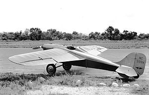
Derived from the side-by-side two-seat cabin monoplane Babcock-Vlcek X Airmaster, the LC-13A featured an open cockpit and an enlarged vertical tail. It was powered by a 75 hp Roché L-267 four-cylinder air-cooled inverted in-line engine. Originally designed and manufactured by Rover of Lansing, Michigan, the manufacture of the 267 cu.in (4.38 l) engine was taken over by Jean A Roché of Dayton, Ohio in 1932. An auxiliary fin on the underside of the stabilizer had to be fitted according the Aircraft Type Certificate 2-389.
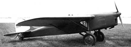
Originally marketed as the Babcock LC-13 by its original manufacturer, then the Taubman LC-13 when the Babcock Airplane Corporation was acquired by Taubman Aircraft. Vearne Babcock left the aviation industry in 1945, and sold the rights to produce his LC-13 to Bartlett Aircraft Corp. at Rosemead, California. This aircraft was developed from the Babcock monoplane of the mid-1930s.
The Bartlett Zephyr was a mid-wing braced monoplane of conventional design with side-by-side seating for two and fixed, tailwheel undercarriage.
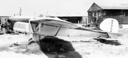
NR998W was modified as a racer.
Plans to mass-produce it were halted by the outbreak of World War II after two were built, X/NC998W and NX18165. There was a brief attempt to revive the design at the end of the war, but nothing came of this. Price was $3,995.
The LC-13A Zephyr of 1941 was a streamlined, single-strut version of the Taubman LC-13, still under ATC 2-389.
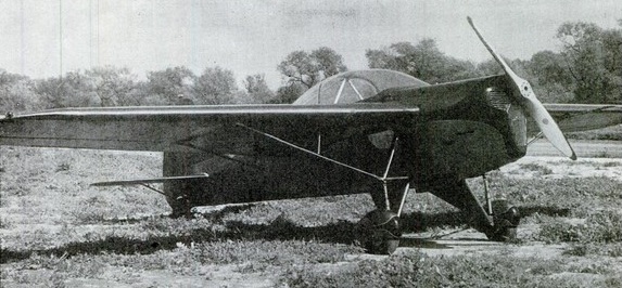
Engine: 1 × Franklin 6A4-150-B3, 150 hp (112 kW)
Length: 21 ft 0 in (6.40 m)
Wingspan: 30 ft 9 in (9.38 m)
Maximum speed: 150 mph (240 km/h)
Range: 500 miles (800 km)
Service ceiling: 18,000 ft (5,500 m)
Crew: one pilot
Capacity: 1 passenger
LC-13A
Engine: 130hp Franklin 6AC or 120hp Martin 333
Wingspan: 30’10”
Length: 20’5″
Max speed: 150 mph
Cruise: 135 mphRange: 450 miles
Seats: 2
LC-13A
Wngine: 150hp Franklin 6A4-150-B3
Wingspan: 30’9″
Length: 21’0″
Load: 685 lb
Max speed: 150 mph
Cruise: 135 mph
Stall: 42 ph
Range: 500 miles
Ceiling: 18,000′
Engine: 75hp Michigan Rover
Wing span: 30’10”
Length: 20’5″
Useful load: 815 lb
Max speed: 100 mph
Cruise speed: 90 mph
Stall speed: 40 mph
Range: 300 mi
Seats: 1
Bartlett Aircraft Corp. was a US aircraft manufacturer founded in Rosemead, California in 1941 to build light aircraft from designs acquired from the purchase of Taubman Aircraft, who in turn bought them from Babcock Airplane Co.
World War II interrupted plans for mass-production. Immediately after the Second World War the Bartlett Aircraft Corporation of Rosemead, California, began production of a lightweight two-seat cabin monoplane designated the Bartlett LC13-A Zephyr 150. This aircraft was developed from the Babcock monoplane of the mid-1930s.
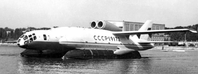
A team led by Roberto Oros di Bartini, a communist who had left fascist Italy for the USSR, presented in 1955 the project of a supersonic flying A-55 medium-range bomber boat. After the comprehensive development and improvement of this project, Bartini approached the creation of an amphibian vertical take-off and landing (SVVP in its Russian acronym).
The experimental vertical take-off and landing amphibian VVA-14 (In Russian: ВВА-14) was characterized by the originality of its design and both its size and its take-off weight surpassed all VTOL aircraft built or projected at the time.
The VVA-14 antisubmarine amphibian began to be developed by government resolution in November 1965 at the UVZ helicopter factory (УВЗ – Ухтомскый Вертолетный Завод) and later transferred to Beriev’s OKB in Taganrog which was later would become the Taganrog Aviation Scientific-Technical Complex (TANTK).
In the process of development of the VVA-14 in the UVZ, together with Bartini participated the helicopter manufacturer VI Biriulin and the later general constructor MP Símonov. In the TANTK NA Pogorielov and GS Panatov were added, who would also later become general constructor. The main objective of the project was to develop new aerial means to combat missile-armed submarines, so it was decided, based on the experimental results, to create an amphibious anti-submarine device capable of detecting, tracking and destroying submarines, both on the surface and while submerged. This requirement demanded an autonomy of 4 hours of flight over an area located 500 km from the base. The development of search and rescue missions was established as a secondary objective.
After the analysis, a conceptual scheme based on the SVVP-2500 design was decided. It was a catamaran-like structure with a rectangular centroplane and a central fuselage in which 12 turbojets were located designed to achieve lift force in vertical take-off. Above the centerplane were two two-stage turbojets for horizontal flight. So-called PVPUs (пневматическое взлетно-посадочное устройство – pneumatic equipment for take-off and landing) were used for landing and take-off operations on water. This unusual composition and the great technical difficulties that arose made it necessary to incorporate researchers and engineers from TsAGI into the development., LII, TsIAM, VIAM and NIAT.
It was decided to develop two prototypes: the VVA-14-1M destined to carry out the functional tests of the selected composition in the different operating regimes and the VVA-14-2M to carry out the vertical take-off and landing tests and the processes transition to horizontal flight.
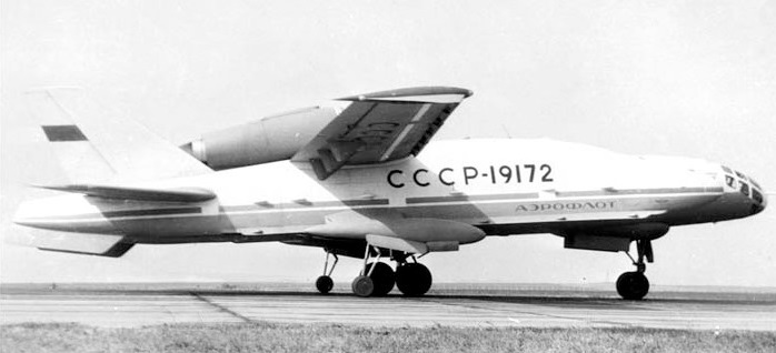
In the late 50s – early 60s, he created the SVVP-2500 vehicle with a take-off weight of 2500 tons in the form of a flying wing with a square center-section and consoles and a power plant made from lifting and cruising engines. In June 1972, the construction of the VVA-14-1M was completed, which did not include the vertical thrust engines and the floats. In July at the TANTK aerodrome, test runs of the prototype began, which was equipped with wheeled landing gear and on September 4 the first flight with pilot Yu took place. M. Kuprianov at the controls and LF Kusnietsov as a navigator. The flight tests that were carried out until June 1975 with a total of 107 flights with a total duration of 103 hours, reaching a maximum speed of 260 km / h.
The VVA-14 was built as a cantilever high wing structure with a supporting centerplane and consoles to which the tailplanes and vertical fins were attached. These cigar-shaped gondolas were designed to contain the PVPU floats. The construction was made fundamentally of aluminum alloys and cadmium steel with anticorrosive coating in attention to the marine operation.
The fuselage was of semi-monocoque construction and was fused with the centroplane to achieve a supporting fuselage. In the bow was located the cockpit for a crew of three. This cabin could be detached from the fuselage in an emergency and ensured the life of the crew without the need for ejection seats.
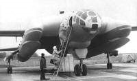
Behind the cockpit was located the lift engine module consisting of 12 Kolosov RD-36-35PR (РД-36-35PR) turbojets and the weapons bay.
The wing was composed of the rectangular-shaped centroplane and the outer sections called OChK of trapezoidal shape with a positive dihedral of 2º. These sections featured flaps along the entire trailing edge, ailerons and flaps.
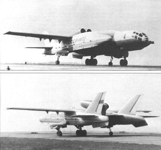
The tail planes were of the cantilever type with a sag of 40º at the leading edge and a surface area of 21.8 m². The elevator had an area of 6.33 m². The two vertical surfaces had a total area of 22.75 m² with a sag of 54º. The area of the rudders was 6.75 m².
The PVPUs (Pneumatic Takeoff and Landing Equipment) were made up of floats 14 meters long, 2.5 meters in diameter and a volume of 50 m3 made up of 12 sections. For its extension and retraction, a complex mechanical-hydro-pneumatic-electric system was used with 12 cylindrical injectors (one for each section). The air for filling was supplied by the compressors of the driving engines. A retractable tricycle landing gear was designed to transport the aircraft over land, with the front landing gear fixed to the fuselage and the main landing gear located on the inner surface of the nacelles. Each undercarriage mounted two wheels.
The combined powerplant consisted of two Soloviov D-30M double-contour turbojets with a thrust of 6800 kg for horizontal flight, located next to each other on separate consoles on the rear of the centerplane and 12 Kolosov RD-36 ascending turbojets. 35PR of 4400 kg each located in pairs with a certain forward inclination in the space of the fuselage behind the cockpit. At the top, an upward opening hatch for each pair of engines covered the air intakes. At the bottom were the nozzles with an adjustable angle of incidence. The use of an auxiliary turbocharged engine was assessed during the project.
The fuel system consisted of 14 tanks for a total capacity of 15,500 liters. A refuelling system at sea was devised.
The steering system of the aerodynamic surfaces was conventional, but in the case of vertical operations and the regime of transition to horizontal flight, 12 additional levers operated in pairs were conceived that allowed the control of the compressed air of the lift engines. The autopilot system allowed course control in all flight regimes.
The flight surfaces had a hot air anti-freeze system and the engines had a fire protection system.
The crew cabin had an oxygen and air conditioning system. An automatic stabilization system was designed to be used during vertical take-off and landing operations and horizontal flight in adverse weather conditions. In the search and rescue version, the VVA-14 was also designed with radio marking systems. The antisubmarine version had to use a Burevietnik search system capable of locating enemy submarines and coordinating the data necessary for their destruction. To detect the submarines, it was planned to equip the VVA-14 with 144 RGB-1U hydroacoustic buoys (РГБ-1У) and up to 100 noise generators, in addition to a Bor-1 magnetic anomaly detector. (Бор-1).
The armament for the antisubmarine version would be located in a hold in the fuselage with a capacity for 2000 kg, being able to incorporate two naval torpedoes or eight IGMD-500 aviation mines (ИГМД-500) or 16 PLAB-250 aviation bombs (ПЛАБ-250). The use of a survival system equipped with active and passive interference launchers was also designed.
In 1974 they settled the VVA-14-1M the PVPU developed at the Bureau of Construction Aggregates of Dolgoprudniencsky and produced in Yaroslavsk, with two large inflatable floats deployed at the bottom of the gondolas. The tests began on June 11, 1975 and included the inflation and collection of the PVPU, which showed that the operation was quite complex and the solution still had to be worked on.
Between 1974 and 1975, 106 cycles of expansion and collection of the PVPU were carried out of which 11 were carried out in flight, both from the water and from the ground.
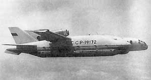
Flight tests confirmed the calculations and showed that at the bottom of the 10.75-meter chord centroplane an effective air cushion was formed at 10 – 12 meters high during landing and at 8 meters the cushion was so dense that test pilot Yu. M. Kuprianov on more than one occasion asked to be allowed to release the controls so that the machine would settle on its own.
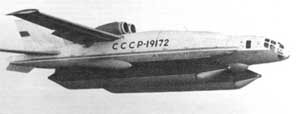
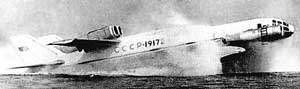
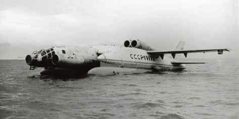
The VVA-14 never made the vertical take-off and landing. The engines for this purpose were never ready. The VVA-14-1M was modified with the installation in the bow of two Soloviov D-30M engines destined to blow and create the air cushion under the centerplane, using the aircraft as an ekranoplane. Among the main modifications made, the inflatable floats were replaced by metallic ones. This model received the designation 14M-1P and was successfully tested in 1976 on the Taganrog peninsula in the Sea of Azov.
Today the remains of this project are preserved in the VVS Museum of Mónino.
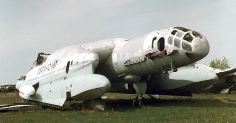
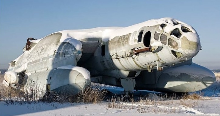
VVA-14
Powerplant: two Soloviov D-30M double-contour turbojets, 6,800 kg and 12 Kolosov RD-36-35PR, 4,400 kg
Wingspan: 30.00 m
Wing area: 21.77 m²
Length: 25.97 m
Height: 6.79 m
Empty weight: 35356 kg
Maximum takeoff weight: 52,000 kg
Fuel weight: 14000 kg
Normal military load: 2000 kg
Maximum military load: 4000 kg
Maximum speed: 760km / h
Cruising speed: 640 km / h
Patrol speed: 360 km / h
Practical range: 2450 km
Practical ceiling: 8000-10000 m
Armament: 2 x naval torpedoes / 8 x IGMD-500 aviation mines (ИГМД-500) or 16 PLAB-250 bombs (ПЛАБ-250)
Accommodation: 3 crew
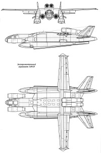
Military version by V.G.Ermolaev. First flown June 1940. 128 were built to July’41. All metal midwinger with “inverted seagull” wing, twin-tail. 3-wheel gear with tail wheel.
Versions:
Er-2 2xAM-35, april 1942.
Er-2 2xACh-30B, december 1943, 300 were built. 3 x 1000kg bombs. Max speed 446km/h. Range 5000km.
Engines: 2 x Klimov M-105, 1050hp
Max speed 491 km/h.
Practical ceiling 7000 m.
Range 4000 km.
Empty weight 6500 kg.
Max takeoff weight 11920 kg.
Wing span 23m.
Length 16.34m.
Wing area 72 sq.m.
Armament One 12.7 mm machinegun “UBT” + two 7.62mm ShKAS, up to 1000kg bombs.
Seats 4.
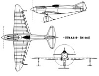
The Stal-8 (In Russian: Бартини Сталь-8) (I-240 in the VVS designation ) was a more practical development of the Stal-6 as a fighter.
It was longer than its predecessor, by the use of a an M-100A (licence-built Hispano Suiza 12YBR) 860 hp engine and was characterized by the presence of a protruding cabin in the upper fuselage, to maintain aerodynamic cleanliness. Unlike the Stal-6 the pilot’s seat was fixed in its upper position.
The Stal-8 construction was mainly the aluminum-magnesium alloy Altmag. The joints were made by spot welding. The cooling system and landing system were very similar to those of the Stal-6. Two 7.62mm ShKAS machine-guns were to be fitted in the top decking over the engine, synchronised to fire through the propeller.
Structurally, the Stal-8 featured a monocoque fuselage formed from metal slats with a C-type profile. The wing was built around two spars with stamped steel ribs. Altmag’s wing coating, 0.5mm thick on the top and 0.8mm thick on the bottom.
The forward part of the wing included the evaporative cooling system. The ‘enerzh’ double skinned surface-evaporation radiators formed the leading edge skin, back to the main-spars. The 4-section ailerons were located on the trailing edge, which could be used as flaps during takeoff, landing and turns. Like the Stal-6, it maintained the system for varying the angle of incidence of the elevator rudders as a function of flight speed.
The 175-liter fuel capacity was achieved through two tanks located near the wing root. The oil tank upper part formed part of the surface of the fuselage in front of the cockpit. In this way, at high speeds, the oil was cooled by the air flow itself.
Construction of the Stal-8 was started in the ships of Factory No.240. Work on the prototype was suspended in late 1934, when work was at approximately 60%. The reasons were various, among them because the GVF, in whose institute Bartini’s brigade worked, was not very in favor of generating military devices in its facilities that did not contribute to their needs. On the other hand, the State Directorate for the Aeronautical Industry (GUAP) did not pay much attention to the project either, considering it “foreign” as it was a responsibility of the GVF. The new Polikarpov fighters I-15 and I-16s were being produced and although the Stal-8 was superior in many respects, there were great doubts about the vulnerability of the cooling system.
Stal-8
Engine: Mikulin M-100, 860 hp (licensed Hispano-Suiza Ybrs)
Wingspan: 9.60 m
Wing area: 15.30 m²
Length: 8.22 m
Height: 2.23 m
Empty weight: 1100 kg
Maximum takeoff weight: 1740 kg
Fuel capacity: 250 kg
Wing loading: 100 kg / m²
Power load: 1.75 kg / hp
Maximum speed at sea level: 550 km / h
Maximum speed at 3000 m: 630 km / h
ROC: 20 m / sec
Practical range: 180 km
Practical ceiling: 9500 m
Endurance: 2.4 hours
Range: 800 km
Take-off run: 190 m
Accommodation: 1