
This tractor monoplane, powered by an 35/42 hp ENV via chain reduction gearing, was tested at Antibes, France, in early 1910 by Jean Bécue.
This tractor monoplane, powered by an 35/42 hp ENV via chain reduction gearing, was tested at Antibes, France, in early 1910 by Jean Bécue.
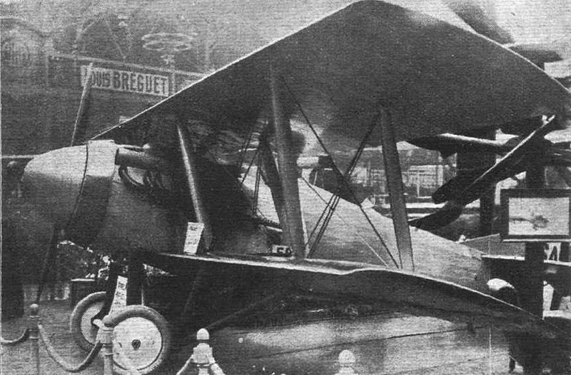
Louis Bechereau established SAB (Societe et Ateliers Bechereau) and was joined in designing a single-seat fighter by Bernard, Bleriot and Birkigt. This, the SAB 1, had the airframe built by Levasseur.
The SAB 1 single-seater fighter, was built by Avions Pierre Levasseur, and was a two-bay biplane powered by a 300 hp Hispano-Suiza 8Fb watercooled eight-cylinder engine. The monocoque fuselage is covered with aluminum in front and fabric in the rear. The engine is totally enclosed in an aluminum cowl, and there is a large spinner over the propeller boss. The radiator is of annular shape and totally surrounding the nose of the machine.
The wing bracing has no struts connecting the top plane with the fuselage. The usual center section struts are replaced by short lengths of lift wires, running from the body to the top of the first pair of inter-plane struts. From the lower ends of these struts, or rather from the bottom spars, two struts converge downwards and inwards, where they are attached to the lower member of the under carriage. The absence of center-section struts and their bracing naturally leaves the pilot’s view unobstructed.
The top surface of both planes is covered with three-ply wood from the leading edge to the rear spar. Ailerons and elevators are balanced by having their leading edges arranged in the form of saw teeth.
The armament consists of four machine guns, two of which are mounted above the fuselage and synchronized in the usual way. The other two are placed in the top plane, some little distance out, and are operated by Bowden control.
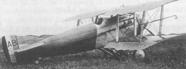
Flight testing was initiated during 1918 in competition with the Nieuport 29, five examples being built. Selection of the Nieuport fighter by the Aviation Militaire resulted in discontinuation of further development of the SAB fighter.
Engine: Hispano-Suiza 8Fb, 300 hp
Span, 30 ft 6 1/8 in (9,30 m).
Wing area, 311.09 sq ft (28,90 sq.m)
Length, 22 ft 7 5/8 in (6,90 m).
Height, 8 ft 4 1/3 in (2,55 m).
Empty weight, 1,726 lb (783 kg).
Loaded weight, 2,474 lb (1 122 kg).
Max speed, 130 mph (210 km/h).
Time to 6,560 ft (2 000 m), 5.78 min.
Armament:
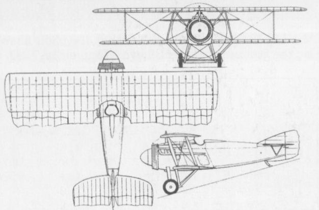
S.A.B. – the Société et Ateliers Béchereau – 1918-1920
After resigning as a director of SPAD (Societe Pour Aviation et ses Derives), Louis Bechereau established SAB (Societe et Ateliers Bechereau) and was joined in designing a single-seat fighter by Bernard, Bleriot and Birkigt. This, the SAB 1, had the airframe built by Levasseur.

The 1911 Beaver monoplane was designed and built by Bert Beaver in the USA.
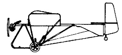
Single seat single engined high wing monoplane with conventional three axis control. Wing has unswept leading and trailing edges, and constant chord; cruciform tail. Pitch control by elevator on tall; yaw control by fully flying rudder with additional fin; roll control by spoilers; control inputs through stick for pitch/roll and pedals for yaw. Wing braced from below by struts; wing profile single surface. Undercarriage has three wheels in tail dragger formation; no suspension on tailwheel and bungee suspension on main wheels. No ground steering. No brakes. Aluminium tube framework, without pod. Engine mounted at wing height driving tractor propeller.
The Beaujon Mach .07 was aimed at amateur constructors, being available only as a sheet of plans.
Length overall: 18.5 ft, 5.61 m.
Sweepback: 0 degs
Total wing area: 165 sq.ft, 15.3sq.m
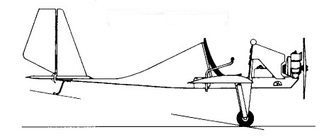
Single seat single engined low wing mono¬plane with conventional three axis control. Wing has unswept leading and trailing edges, and constant chord; conventional tail. Pitch control by elevator on tail; yaw control by fin mounted rudder. Control inputs through stick for pitch/roll and pedals for yaw. Wing braced from below by struts; wing profile FX 72 MS 150 modified; double¬surface. Undercarriage has two wheels with tailskid. Fuselage partially enclosed. Engine mounted above wing driving tractor propeller.
The Easy Flyer was one of the earliest microlights offered in plan form for amateur constructors. Designed by H Beaujon, it was first built in 1976 and offered for sale the following year. It is of classical configuration, remaining very close to the traditional aircraft concept, and differs really only in those aspects of specification and performance where change was essential to qualify it as an ultralight. H Beaujon was one of the first designers to advise using two-¬stroke engines for aeronautical use, and in this instance chose a Rockwell JLO L 395 single cylinder motor weighing 59 lb (27 kg).
Engine: Rockwell JLO L 395, 24.5hp at 5500rpm.
Prop diameter/pitch: 46×20 inch, 1.04 x 0.45 m
Power/unit area: 0.28 hp/sq.ft, 3.0 hp/sq.m.
Length overall: 15.3 ft, 4.64 m
Height overall: 4.8ft, 1.42m.
Wing span: 25.1ft, 7.87m
Total wing area: 89 sq.ft, 8.3sq.m
Constant chord at root: 3.8ft, 1.11m
Wing aspect ratio: 7.5/1.
Empty weight: 175 lb, 79kg
Max take off weight: 372 lb, 169kg.
Payload: 197 lb, 89kg.
Max wing loading: 4.18 lb/sq.ft, 20.4kg/sq.m.
Max power loading: 15.2 lb/hp, 6.9kg/hp
Max level speed: 79mph, 128kph.
Cruising speed: 65mph, 104 kph
Stalling speed: 28 mph, 46 kph.
Max climb rate at SL: 490 ft/min, 2.5 m/s.
A developed version, the BJ-3A appeared in 1968 and this was followed by the BJ-4, two of which were built for the 1970 World Championships, in which the existing BJ-3 wings were married to a new fuselage and tail unit, the T-tail being replaced with a taller fin and rudder and an all-flying tailplane repositioned on the fuselage behind the rudder.
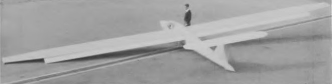
Designed by P. J. Beatty of Johannesburg and W. A.T. Johl especially for South African climatic conditions and the strong thermals experienced in that country, the single-seater BJ-3 was based on experience gained with the successful BJ-2. The prototype, which was built by Performance Sailplanes of Activia Park, Germiston, made its first flight in 1965 and a BJ-3 set up an international speed record over a 500km triangular course on 28 December 1967 of 84 mph.
The BJ-3 is of largely all-metal construction except for the fuselage, which is of glassfibre from the nose to the wing spar, the remainder being a semi-monocoque with duralumin skin and stringers. Landing gear consists of a retractable monowheel aft of the centre of gravity, with a brake, and a retractable nosewheel; in its original form the BJ-3 was to have had a nose-skid. The one-piece plastic canopy hinges to open at the rear, jet fighter fashion, and the BJ-3 is fitted with a full instrument flight panel as well as VHP radio and oxygen. The wings have a basically duralumin load-carrying structure with a wide spar, and are covered with polystyrene foam with an outer protective skin of glassfibre which gives a smooth finish. An unusual feature is the very generous flap area, the Fowler flaps covering no less than 80% of the span and increasing the wing area by 30% when lowered to their full 30°; they have a steel tube spar and, like the main wing structure, are covered in polystyrene foam and glassfibre. Four sets of double DFS-type air brakes are fitted above and below each wing, and the ailerons are of foam and glassfibre. Another unusual feature for a sailplane is a tail braking parachute housed in the tail cone. The fin and rudder are of duralumin, whereas the fixed-incidence tailplane is of plywood-covered spruce construction.
A developed version, the BJ-3A appeared in 1968 and this was followed by the BJ-4, two of which were built for the 1970 World Championships, in which the existing BJ-3 wings were married to a new fuselage and tail unit, the T-tail being replaced with a taller fin and rudder and an all-flying tailplane repositioned on the fuselage behind the rudder.
Beatty-Johl BJ-3
Span: 16.15 m / 52 ft 11.75 in
Length: 7.5 m / 24 ft 7.25 in
Wing area: 12.3 sq.m / 132.4 sq.ft
Wing section: NACA 661 212/0009-64A-0.8
Aspect ratio: 20 (flaps in)
Aspect ratio: 15.82 (flaps extended)
Max weight: 522 kg / 1,151 lb
Water ballast: None
Max wing loading: 42.44 kg/sq.m / 8.69 lb/sq.ft
Max speed: 177 mph / 154 kt / 285 km/h (in smooth air)
Stalling speed: 28.5 kt / 53 km/h
Max aero-tow speed: 138 mph / 120 kt / 222 km/h
Min sinking speed: 0.67 m/sec / 2.2 ft/sec at 46 mph / 40kt / 74 km/h
Best glide ratio: 40:1 at 81 mph / 70kt / 130 km/h
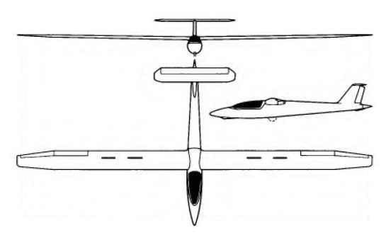
Constructions Aeronautiques du Beam was responsible for production of the Minicab two-seat lightweight cabin monoplane designed by Yves Gardan. Designated Beam Minicab GY-201, it was powered as standard with a 65 hp Continental flat-four engine.
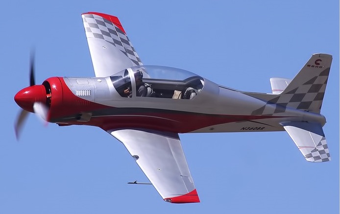
The Bear 360 is a new manufacture, all metal, high-performance, 360 HP radial M-14P powered, tandem seating, Warbird styled aircraft, created by the American-Russian design team that includes Russian aircraft designer, Sergey Yakovlev, and American combat fighter pilot and air racer, Skip Holm. Sergey Yakovlev developed the Bear 360 to military specifications, to meet FAR Part 23 requirements as well as full Russian Military Specifications.
The Bear 360 two place tandem seated cockpit has dual flight controls. Sold in the experimental category, the Bear 360 meets specifications for this type of FAA aircraft category and is a fully documented FAR Part 23 engineered aircraft.
The Bear 360 is powered by the Vedeneyev M-14P, 360 horsepower, supercharged, air-cooled, reciprocating nine-cylinder radial engine. The M-14P will maintain sea level power to 7,500 ft altitude. Engine controls are simplified through fuel scheduling hardware so that the pilot operates only the throttle and RPM controls. Engine starting is electric. Vedeneyev dictates the M-14P’s TBO in terms of cycles, which is a common practice in Russia and Eastern Block countries. In the West and Europe’s JAR it has certified the engine for a 1500 TBO. The Bear 360 has a three bladed hydraulically controlled constant speed MT Propeller certified to meet FAA specifications.
The Bear 360 wing has a NASA 63-215 root and 63-412-tip laminar flow airfoil. Lateral stability has been demonstrated in the full wind tunnel to 30 degrees angle of attack with flaps full up or full down. The wing is constructed around a single piece tapered main spar with stressed aluminum flush riveted skin over conventional stamped aluminum ribs. Wing dihedral is 5.0 degrees. Fuel is contained entirely in the wing structure and no bladders or individual tanks are used except the center sump tank, which feeds the engine (An auxiliary external centerline fuel tank is also available on all aircraft). The landing gear system attaches to the main spar and its surrounding structure. The wing is attached to the fuselage as a single piece structure and the four attach points are precision machined so there is no special rigging required for wing removal/replacement.
The Bear 360 flight control surfaces are all-metal construction and mass balanced. Flight control actuation is through torque and push – pull tube assemblies; no cables are used. Trim on all three axis is electric. Controlled with standard individual push-pull controls.
The Bear 360 fuselage is semi-monocoque, all metal, flush riveted construction. The cockpit width at the sliding rails is 25.5 inches. The windscreen is 3/8ths polycarbonate, and the canopy is a large unobstructed bubble that slides aft, operated by a hand crank. The canopy may be left partially open during start, taxi, takeoff/landing and pattern operating speeds.
The landing gear is conventional, retractable, including the tail wheel. The main gear track is 9.3 feet. The main gear struts are oleo-pneumatic accommodating 8.00X10 inch tires. The brakes are of US manufacture employing two actuation cylinders per brake rotor.
The tail wheel is steerable and pivots through 360 degrees for ground handling/towing. The landing gear retraction and extension is hydraulically operated. An electro-hydraulic pump of US manufacture provides hydraulic pressure. Emergency landing gear extension is by means of a pneumatic charged unlock of the over-center locking mechanism and blow down system. The landing gear system normal operating pressure is nominally 800 PSI. The Bear 360 electrical system is 28 volts and is charged by a 35 amp B&C Specialties SK35 engine driven alternator, and a 24 VDC battery.
The fuel system consists of three wing fuel reservoirs, an engine driven fuel pump, and an emergency electrical fuel boost pump. Wet wings accommodate 37 US gallons each and the sump/feeder tank in the bottom center of the wing holds the remaining 2 gallons of the fuel system, for a total of 76 gallons. For normal operations the fuel boost pump is not required as the engine driven mechanical fuel pump provides both the suction to pull fuel from the sump tank as well as pressure for normal fuel scheduling throughout the engine operating range. The fuel boost pump provides full normal engine operation for starting, takeoff and landing. Additionally, an optional removable 22 US gallon centerline mounted external tank, similar to a WWII drop tank design, is available for all aircraft. This external tank fuel is delivered via an electric fuel pump.
The flaps are electrically actuated, via an electric flap switch and can be manually stopped at any flap position. This 3-position flap switch commands flaps in these positions: flaps up, flaps stopped, or flaps lowering. An electrically actuated speed brake is mounted near the aerodynamic center of the aircraft between the flaps. The speed brake can be employed throughout the entire aircraft flight envelope with minimal change to steady state trim settings. The speed brake can also be employed as a flap for landing.
The cross country baggage compartment or equipment bay is 4.2 cubic feet and is designed to carry airline carry-on-baggage for both pilots. It will accommodate a maximum of 65 pounds.
The Bear 360 had over 1,000 hours of wind tunnel and load testing to destruction, and undergone extensive flight-testing to US military standards in the hands of test pilot Skip Holm, to be issued FAA approval.
The aircraft exhibits buffet 6 knots above the stall, and stalls at 81 KTS. The engineering estimation at stall altitude was 78 KTS at an empty weight of 1878 pounds plus fuel, whereas the prototype was 1901 empty plus fuel/PAX on board. The stall was straightforward, stalled with a mild buffet, and did not have any tendency to snap.
Four different configuration options were offered in 2015:
Ready to Fly (RTF)
Warbird Edition (2015: US$310,000)
Skip Holm Signature Series
Almost Ready to Fly (ARF) Does not include: Engine, propeller, avionics, interior or paint. Cockpit, engine, landing gear and wheel wells are painted in 5th generation fighter grey. 2015 US$185,000
The Skip Holm Signature series was the luxury variant of the Bear 360, including a choice of high-end avionics, autopilot, fully customized paint, plus well-appointed cabin amenities such as plush, hand-tooled, leather seating and panels, custom built by the Yakovlev factory.
The Almost Ready to Fly (ARF) Aircraft excludes Engine, Propeller, Avionics, Interior and Paint. If a buyer provided engine and propeller to the factory, these would be installed without charge.
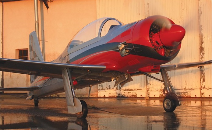
The Bear was under production in Orenburg, Russia, in 2015.
Engine: Vedeneyev M-14P, 360 hp / 420 hp (optional)
Wingspan: 23.10 ft
Wing area: 93 sq ft
Length: 23.25 ft
Gross weight: 2760 lb
Empty weight: 1860 lb
Fuel capacity: 76 USgal
Wing loading (at gross): 29.7 lbs/sq ft
Vne: 280 kias
Max cruise (at Sea Level): 250 kias
75% cruise (at Sea Level): 210 kias
Stall (landing configurations) Vso: 70 kias
Stall (clean) Vsi: 78 kias
S L rate of climb: 1850 fpm
Max range @ SL (20 Min reserve): 890 nm
Take off roll at sea level (Std day): 825 ft
Take off roll over 50 Ft obstacle: 1050 ft
Landing at sea level (Std day): 825 ft
Landing over 50 Ft obstacle: 1100 ft
Max roll rate: 180 Degrees/Second
Max ‘G’: +6, -3
Fuel: 100 Low Lead Av Gas, 91 Octane with NO Ethanol

