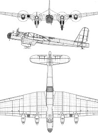
The Bolton 1-B was built after WW2.

The Bolton 1-B was built after WW2.
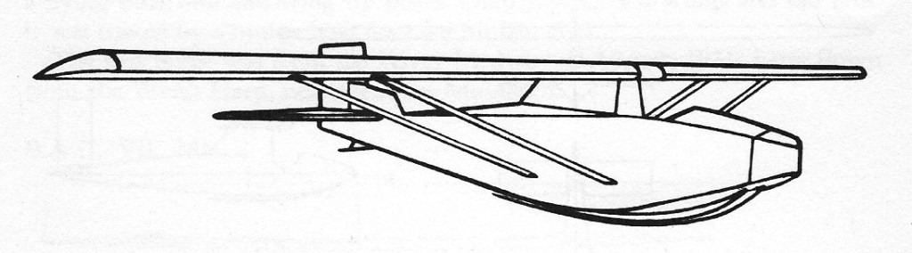
A single-seat secondary glider was designed by a Mr Bolton of the Kent Gliding Club, UK. It first flew on 3 April 1932.
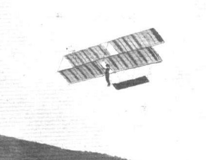
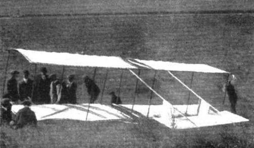
The machine is of Chanute type, built by two Canterbury Aero Club members, Messrs. Bolt and Angus, in New Zealand, in early 1912. Great success was attained in towed flights with passengers, about fifty trips through the air being indulged in before a bad smash through faulty towing put an end to experiments for a week or so. Among the many passengers carried was a lady, the wife of Mr. Johnassen, Club Engineer.

The two-seat Bolkow Bo 209 Monsoon first flew in 1967.


Bo 209-150
Engine: Lycoming O-320, 150 hp
Prop: fixed pitch
Bo 209-150
Engine: Lycoming IO-320-D1A, 160 hp
Prop: Constant speed
Wingspan: 27 ft 6.75 in / 8.40 m
Length: 21 ft 7.75 in / 6.60 m
Empty weight: 1067 lb / 484 kg
Max payload: 504 lb / 229 kg
MTOW: 1807 lb / 820 kg
Max cruise 75% 8000ft/2440m: 148 kt / 170 mph / 274 kph
ROC SL: 1180 fpm / 360 m/min
Service ceiling: 18,100 ft / 5520 m
Max range, 65%, no res: 647 nm / 745 mi / 1200 km
Cabin length: 4 ft 7 in / 1.40 m
Cabin width: 3 ft 3.75 in / 1.01 m
Cabin height: 3 ft 6.75 in / 1.11 m
Seats: 2 side-by-side
Bo 209S
Engine: Rolls-Royce Continental O-240, 130 hp
Non-retractable nosewheel
Wing: non-folding
MBB Bolkow 209-160RV
Engine: Lycoming IO-320-D1B
prop: MT 3 blade VP
Cruise: 125 Kt
Seats: 2
Retractable Nosegear, Folding Wings


Bjorn Andreasson of Sweden, originally designed and constructed the prototype BA-7 in his garage in San Diego, while employed as an engineer at Convair. Andreasson’s BA-7 major objectives were good performance, economy, unusual visibility and maneuverability. Fifteen hundred hours of work, one thousand dollars, and a used seventy-five horsepower Continental engine was the expenditure in the project.
Andreasson first flew his 75hp Continental powered BA-7 homebuilt prototype on 10 October 1958.

The fuselage is a sheet metal box with exterior longerons and only three bulkheads. The horizontal tail is all-flying; the vertical tail has been changed to conventional fin-and-rudder combination and swept to enhance directional stability.
The wings, using an airfoll only 8.5% thick, have an extruded spar at 30 percent, and a light rear spar at 75% chord. A heavy magnesium skin adds strength, and countersunk rivetting ensures smoothness. By undoing the rear spar bolts, the wings can be folded alongside the fuselage for easy towing or storage, an attractive feature.
The visibility comes from the slight forward sweep of the wings, the occupants sitting forward of the spar. The one piece free blown canopy is hinged at the rear and held down by two latches, one of which is sufficient to hold it at maximum speeds. The main gear is built around two tapered steel rods, anchored to a box beam. The nose gear has a coil spring, is air damped, and is steared by the rudder pedals. Elevators and ailerons are actuated by a single centrally located stick; rudder pedals are dual, and a single hydraulic cylinder gives braking action to both wheels.
The flap control incorporates a nonreversing mechanism that holds the flap in any selected position. The fuel supply is positioned over the center of gravity behind the pilot, and with the 75 horsepower engine in the prototype, the twenty US gallons provides six hundred miles range. A plastic tube is used to indicate the fuel level.
Liftoff is at about sixty-five miles per hour, and an actual top speed of over 150 has been achieved. A more powerful engine is contemplated for the production version. Present approach speeds are on the order of 70-85, and touching speed approximately 55 miles per hour.

Andreasson was producing three copies of the MFI Junior, as it’s been renamed, and with Malmo Flygindustri, Mahno, Sweden, a series of ten to test its market potential.
A couple of years later Andreasson returned to Sweden where he joined up with theMakno Flygindustri company, later becoming head of the Aircraft Division of Malmo, a subsidiary of Saab Scania.
While there he put together an improved version of his BA-7, powered by a flat-four engine of 100hp. Following its test flight, the BA-7 design rights were acquired by Malmo Flygindustri and the BA-7 was renamed Malmo MFI-9 or just MFI to the team. Under the designation MFI 9 Junior, the first prototype Junior took to the air on 17 May 1961. Limited production commenced in 1962 and the first production model flew on 9 August 1962. The Junior is certificated for normal and Utility categories and for glider towing.
The basic MFI, of which 25 were produced by Malmo, had reasonably good beginnings and in 1962 Bolkow Apparatebau GmbH (Germany) became involved. Bolkow started producing the Bolkow B208 Junior as an expansion of the MFI-9 under licence to Malmo and by 1970 had produced 200 examples.

A manufacturing licence agreement was reached with the West German firm of Bölkow-Entwicklungen KG, Munich, and licensed production began in 1962 in Germany at the Bolkow factory as the Bo208 Junior.

Two years later a new model, the Bo208C, emerged with the addition of electrically operated flaps, a trailing link nosewheel suspension and a former optional longspan wing as standard. Amongst other features, the Bolkow had tubular steel main gear well before Cessna adopted the concept. The Bo208 has only required three relatively minor mandatory modifications. Its only real problem came with the nosewheel it was prone to falling off once the aircraft was airborne. The addition of the trailing link nosewheel suspension in the B model sorted that problem out. The Bolkow remained one of the fastest 100hp two seat light aircraft with a duration of four hours in the air (range 804.7km with maximum payload), cruis¬ing at 120 mph. Aerobatic. 186 built in total.
In 1964 nine examples were assembled in Burbank, California, by Pioneer Aviation, the U.S. distributor. The 1964 price was US$7800 fully equipped but minus radios, with its American type certificate A1EU.

Slab tail surfaces were featured on the prototype in original form along with a system of springs to return the elevator to neutral or trimed position. The spring tension is not affected by speed, the stick loading remains light at high speed. With an anti-servo tab the feel heavies up as the speed increases. Andreasson eventually adopted the anti-servo tab for better all-round efficiency. After some experimentation, the rectangular rudder was abandoned for the more conventional swept tail.
The large, one-piece canopy is just under 1/8in thick. It measures 38in across at the widest point and has a base length of 30in. American models have a single, centrally located canopy latch instead of the left and right side handles fitted to German aircraft. The seats are independently mounted. A luggage compartment is situated directly behind the seats and below the fuel tank. It is accessable from the cockpit only.

In order to achieve the excellent visibility from the cockpit and still keep the centre of gravity within permissable limits, Andraesson swept the wings forward three degrees. The employment of the “droop snoot” leading edge has the effect of providing a more forward centre of pressure at higher angle of attack. Structurally the fuselage has four external longerons and the skins are all flat sheets. To prevent excessive vibration, two longitudinal stiffeners are formed in each side panel. The single spar (an I-beam extrusion) wing is composed of a minimum of parts, each panel having only seven ribs. The airfoil is an NACA 23008.5 section modified at the leading edge. The main legs of the landing gear are flexible steel shafs weighing about eight pounds each.
Reinforced fibreglass mouldins are used at the wing tips and on the engine cowling. Self-aligning bolt bearings are used in such places as the top engine mount lug and fuselage wing strut fittings.
Dual throttles, located on the extreme right and left side of the instrument panel, are connected by a transverse torque tube behind the panel. Friction on the torque tube is adjusted by a small knob in the centre of the panel.
Cleveland hydraulic brakes are actuated simultaneously by a lever mounted on the left side of the central keel. A simple ratchet lock disengages easily by pulling the handle a little to one side. The anti-servo trim tab has a lever in the cockpit moving a sheathed, 1/8in steel rod connected to a 1.5in long bellcrank at the tailpost. The bellcrank, fitted with a small friction-disk brake, is linked to the tab by a short rod.
Aileron mass balance weights on the BA-7 were fully enclosed in the wing tips. They are in about the same place on the Junior, but project into the airstream with up aileron. Rudder weights are entirely external and the horizontal tail has a heavy leading edge, largely with the weight necessary for balance.
In its original form the Junior was equipped with manually-operated self-locking flaps which were quick and positive. However, the operating handle was situated above shoulder level between the occupants and on the rear cross tube. During certification tests in Germany, the inspector banged his head several times on the handle and this prompted a recommendation that the system be operated electrically. A small window actuating motor from a Mercedes 220 automobile was adapted for aircraft use.
The toggle switch controlling the flaps is located next to the throttle. A simple flap indicator is an endless sheathed cable running from the flaps to a small pointer projecting through a vertical slot on the instrument panel. The slot is marked to show any position from 0 to 35 degrees. A second, electrical fuel pump is fitted.

In the original BA-7, the elevator was not adequately powerful to keep the nose up at low speeds, which meant that the aircraft had to land faster than should have been necessary. By increasing the elevator area on the Junior and giving it an inverted camber, control was more powerful and touchdown speed was reduced. Recommended approach speed is 70 kt / 80 mph. The Junior’s ailerons are small, 32in x 10.5in, but effective and a 360 degree roll takes under 3 seconds. The landing gear is sprung, with 500 x 5 tires all round. The thrust line is offset 1.5 degrees to the right.
Empty weight has been raised from 590 lb of the BA-7 to 750 lb, due primarily to the use of aluminium instead of magnesium and the use of the 100 hp Continental with full electrical system.
Some 210 Bolkows were built in the years following 1962, ceasing in 1970.

Meanwhile, Malino had further developed the MFI-9 from which came the MFI-9B Trainer with an enlarged cabin. The 9B was purposely designed for the military as a basic trainer, although the type later became very useful in a ground attack role. Malmo, which built nearly 50 9Bs, was hoping that the Swedish Air Force would acquire its trainer, but that didn’t eventuate.

The MFI 9B was followed by a T tailed version with provision for underwing stores, evolving to the MF 15 which was used a military trainer.
About five rocketting 9Bs saw service with the Biafran Air Force during the Biafra-Nigeria Civil War in 1969, when Biafra was fighting for its independence from the much larger country. The five 9Bs actually made up the air component of the BAF, along with a few inactive Harvards. Known as “Biafran Babies”, the militarised 9Bs were flown by Swedish and BAF pilots and were up against the likes of the Nigerian Air Force’s (NAF) MiG-17 jet fighters and the much bigger Ilyushin Il-28 twin-engine jet bombers.
It is reported that the little 9Bs either severely damaged or totally wrecked numerous MiGs and three of the NAF’s six Il-28 bombers during ground attack, hit-and-run operations. Other Nigerian targets attacked by the 9Bs included key airfields, armoured vehicles, troop and transport lines and oil depots. One 9B returned to base from a low-level sortie with 12 bullet holes in it.
The 9B was also used in a ‘MiniCOIN’ role, a contraction of miniature counter-insurrection. At the end of seven months of flying combat missions, the BAF’s strike force assets numbered two. Two MFI-9Bs had been shot down with the loss of their pilots and one had been damaged beyond repair.

Bolkow Bo.208
Engine: Continental O-200-A, 100 hp
Prop: McCauley 1A 100 MCM 6758 metal fixed
Wingspan: 24 ft 4 in
Length: 19 ft
Height: 6 ft 6 in
Wingarea: 93 sq.ft
Tread: 6 ft 4 in Fuel capacity: 21.1 USG
Load factor utility: +4.40 / -1.76
Empty weight: 794 lb
MAUW utility: 1275 lb
MAUW normal: 1325 lb
Fuel capacity: 21 USG
Fuel & oil: 136 lb
Baggage: 45 lb
Vne: 153 kt / 176 mph
Max speed SL: 125 kt / 143 mph
Cruise 1500ft / 2500rpm: 106 kt / 122 mph
Cruise 9000ft / 2600 rpm: 109 kt / 126 mph
Landing speed: 51 kt / 59 mph
ROC SL 75kt: 690 fpm
Service ceiling: 13,000 ft
Cruise range 12,000ft / 2500 rpm: 480 mi
Endurance: 4 hr
TO roll: 900 ft
TO to 50 ft: 1720 ft
Landing roll: 770 ft
Landing dist from 50ft: 1480 ft
Seats: 2.
Malmo & Bolkow MFI-9HB
Engine: 100 hp.
Span: 24ft 4in.
Wing area: 93 sq.ft.
Length: 19ft 2in.
Max wt: 1268 lbs.
Empty wt: 750 lbs.
ROC: 900 fpm.
Cruise: 113 kts.
Seats: 2.
MFI-9 Junior
Number built: 25
MFI-9 Trainer
Number built: 70
Bolkow 208C Junior
Engine: Rolls Royce Continental 0-200A, 100 hp
Wingspan: 26 ft 4 in / 8.02 m
Length: 19 ft 0 in / 5.79 m
Empty Weight: 874 lb / 380 kg
Max All Up Weight normal: 1390 lb / 630 kg
Max All Up Weight utility: 1320 lb / 600 kg
Fuel Capacity: 21 Imperial Gallons (100 Litres)
Max cruise Speed: 111 kt / 127 mph / 205 kph
Max ROC SL: 785 fpm / 240 m/min
VNE: 153 kt
Service ceiling: 14,780 ft / 4500 m
Range max fuel: 538 nm / 620 mi / 1000 km
Seats: 2


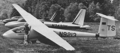
Derived from the Akaflieg Stuttgart FS-24 Phonix, the first sailplane to be built of glassfibre, the Phoebus high-performance single-seater was designed jointly by R. Under, R. Eppler and H.Nagele, the last two of whom had directed design work on the Phonix. The prototype was built by R.Linder and made its first flight on 4 April 1964; it came third in the Standard Class contest in the 1964 German National championships and 8th in the 1965 World Gliding Championships at South Cerney.
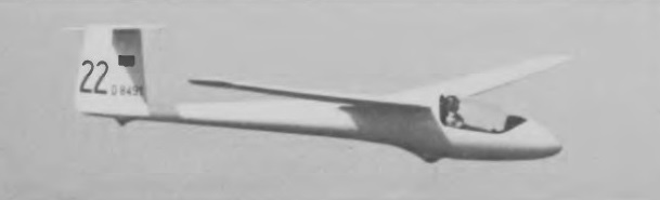
Production of the Phoebus was undertaken by Bolkow GmbH at Ottobrun, and three versions appeared:
the Phoebus A, the initial production Standard Class 15m (49ft 2.5 in) span variant which had a fixed monowheel and tail bumper for landing; the Phoebus B, which appeared in 1967, was the same as the A but with a retractable monowheel, and the Phoebus C was a 17m (55ft 9in) span version with a retractable monowheel and a tail braking parachute.
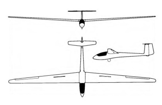
The Phoebus was one of the most commercially successful of postwar German sailplanes, a total of 253 having been built when production ended in 1970, and the type did well in contests; at the 1968 World Gliding Championships at Leszno, Poland, Phoebus C pilots took second and sixth places in the Open class and a Phoebus also took third place in the Standard class. The Phoebus, like the Phonix before it, has a basically balsa wood/glassfibre sandwich structure but with a stronger skin. The shoulder wing has air brakes at the 70% chord line and the one-piece all-moving tailplane is mounted on top of the fin to avoid downdraft from the wing. The fuselage is a monocoque structure similar in outline to that of the Phonix, and the pilot is seated under a one-piece canopy, with a control mechanism which is a simplified development of the Phonix’s. Compared to the latter, the Phoebus also has better high speed performance and improved gust response.

Phoebus C
Wing span: 17.0 m sq / 55ft 9.25 in
Wing area: 14.06 sq.m / 151.4 sq ft
Length: 22 ft / 6.98 m
Aspect ratio: 20.55
Airfoil: Eppler 403
Empty weight: 235 kg / 518 lb
Max weight: 375 kg / 827 lb
Payload: 125 kg / 276 lb
Water ballast: None
Wing Load: 26.71 kg/sq m / 5.43 lb/sq ft
Max speed / Max rough air speed: 124 mph / 108 kt / 200 km/h
Stalling speed: 31 kt / 58 km/h
L/DMax: 42.3 @ 90 kph / 49 kt / 56 mph
MinSink: 0.55 m/s / 1.8 fps / 1.07 kt at 43 kt / 80 km/h
No. of Seats: 1
No. Built: 250
This company was founded on May 1,1956 by Ludwig Bolkow, becoming established at Ottobrunn bei Munchen in 1958. Until January 1,1965 was known as Bolkow Entwicklungen KG. Boeing acquired a one-third interest in the business. Bolkow held a 25% interest in Entwicklungsring Sud EWR). Aircraft produced include the Bo 207 four-seat light aircraft, BO 208 C Junior (a license-built version of the Malmo MFI-9) and the BO 105 five-seat light helicopter, which featured a rigid main rotor of glassfiber-reinforced plastics. This helicopter continued in production under the designation MBB BO 105, signifying that it was then built by Messerschmitt-Bolkow-Blohm, and most recently it became a Eurocopter product.
Messerschmitt joined with Bolkow in 1970 to form Messerschmitt-Bolkow. The Bolkow company was absorbed into Messerschmitt-Bolkow-Blohm which by 1990 was part of Deutsche Aerospace.
The Bolkhovitinov AVF-6 Favzayat single-seater training glider was developed by Victor Fiodorovich Bolkhovitinov, a student of the Air Fleet Academy, in 1924.
Structurally it was a sesquiplane with ailerons on the upper wing and a rear fuselage with a flexible structure. The pilot was located in a small nacelle attached to the lower wing. The landing gear was made up of skis. The tail unit was of the conventional type.
The construction of the glider was carried out at the Duks factory.
In 1924, the AVF-6 participated, together with the AVF-18 “Pioner” in the national competitions in Koktebel.
Only the one was built.
Upper wingspan: 11.5 m
Lower wingspan: 6.2 m
Length: 6.6 m
Height: 2.22 m
Wing area: 25 m²
Empty weight: 68 kg
Seats: 1
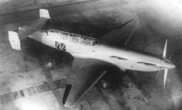
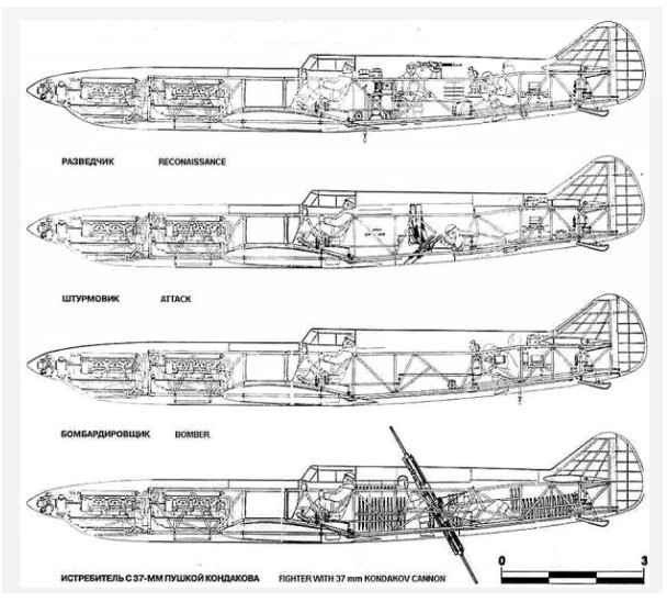
In 1936 Bolkhovitinov considered the problem of high-speed military aircraft. He choose a layout with two M-103 engines, installed one after the other (tandem) with the transmission on coaxial propellers.
He constructs a paired set of engines, followed by bench testd. Bench tests were promising, so in 1937 under the leadership of Bolkhovitinov a high-speed short-range bomber was conceived, indexed “C” (there were several options for decoding the index: “Stalin,” “Spark,” “Spartacus”).
In parallel with the construction of short-range bomber DB, Bolkhovitinov began the design of another aircraft, equipped with a similar twin powerplant. This a project of high-speed long-range fighter-1 twin engine M-107. This was designated “I”. The development was carried out until the spring of 1941 however, an unexpected obstacle has stopped development of the machine. April 25, 1941 Bolkhovitinov was summoned to a meeting of Deputy People’s Commissar Balandin aviation industry. Present at the meeting, Director Motor Works Lavrent’ev and chief designer of engines Klimov reported the impossibility of creating a two-seat trainer M-107P engines.
The main cause of failure was it was thought that in this engine the elongated shaft at working speeds could have resonance problems. Bolkhovitinov were asked to choose any other type of engine available in the country and to convert it for the project. The designer chose the diesel M-40, and while it was heavy, but consumed half as much fuel.
Change the engine caused change for the whole project. Preliminary survey was conducted during May – June 1941, returning to the designation “C”.
I-1 was then included in the plan of an experimental aircraft in 1941, due to the large similarity of the scheme and design of aircraft with “C”, 2M-103 and “C-2”, equipped with one engine M-103 (front-engine was left in place, but its transmission has been disabled from the second propeller.
In general, the draft I-1 was tested by repeating the “C”, but with a much more powerful Klimov M-107 engines. Different from the prototype were vertical stabilizer and skid. The stabilizer was 4.5 m without end plate.
This fighter was never completed due to the refocusing of the bureau.
The draft I-1 had been identified, many new technological approaches for assembly, riveting and bonding aircraft components, in-flight pilot’s ejection, corresponding to speed range 600-750 km / h.
Around mid-1941 TsAGI study of was co-axial propellers completed, with the following conclusions:
During the war, however, put into practice the results of the research was not possible.
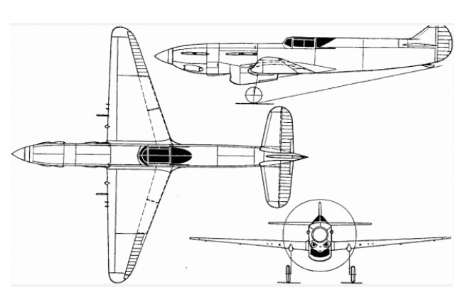
With the intention of creating a high speed light bomber, Viktor Bolkhovitinov designed what is commonly referred to as the Bolkhovitinov S or Sparka. During flight trials the Soviet Air Force (VVS) referred to the aircraft as S-2M-103, for skorostnoy (high speed) with two M-103 engines; however, a number of other designations have been applied over the years. The common “Sparka” designation means twin—because the aircraft had two engines mounted in tandem. Other designations are BBS-1 for blizhniy bombardirovshchik skorostnoy (short range bomber, high-speed), BB for blizhniy bombardovshchik (short range bomber), and LB-S for lyohkiy bombardirovshchik-sparka (light bomber-paired).
The Sparka was a low-wing aircraft of all-aluminum construction with stressed skin. The aircraft had a twin fin tail to increase the rear gunner’s field of fire. The undercarriage was fully retractable; the main gear retracted toward the rear, and the wheels rotated 90 degrees to lie flat within the wings. The pilot and navigator/bombardier/gunner sat in tandem under a long canopy. Between the pilot and second crew member was a small bomb bay for 882 lb (400 kg) of bombs. A plexiglass section on the bottom of the aircraft just aft of the bomb bay provided the bombardier a view of the ground. The aircraft was 43 ft 4 in (13.2 m) long and had a relatively short wingspan of 37 ft 4 in (11.38 m). The Sparka weighed 12,460 lb (5,652 kg).
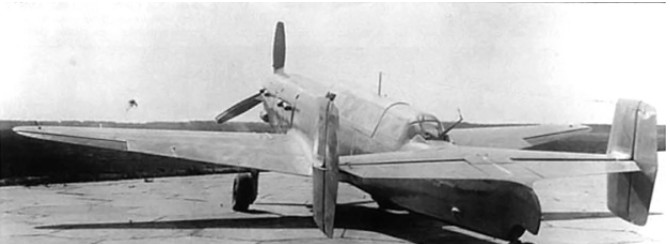
The Sparka was powered by two Klimov M-103 engines positioned in tandem in the aircraft’s nose. Each engine drove half of the aircraft’s six-blade, coaxial contra-rotating propeller unit. This engine and propeller arrangement was similar to the FIAT AS.6 installed in the Italian MC.72 and the Hispano-Suiza 12Y installed in the French Arsenal VB 10. With this engine arrangement, the front engine drove the rear propeller, and the rear engine drove the front propeller via a drive shaft that ran through the Vee of the front engine.
The Klimov M-103 engine was derived from the M-100, which was a licensed copy of the Hispano-Suiza 12Ybrs. The M-103 had a 5.91 in (150 mm) bore and 6.70 in (170 mm stroke). Total displacement was 2,200 cu in (36.05 L). The engine produced 960 hp (716 kW). A radiator was installed in a large duct just below the rear engine, and it cooled both of the Sparka’s engines.
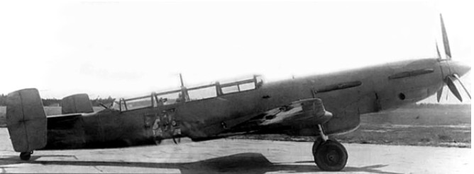
Bolkhovitinov started design work on the Sparka in 1937, and prototype construction began in July 1938. The aircraft made its first flight in January 1940 (some say late 1939) with B. N. Kudrin at the controls. VVS testing took place from March through July 1940. The Sparka showed good speed, reaching 354 mph (570 km/h). However, the take-off run was excessive, landing speeds were high, and visibility over the nose was impaired. In addition, some trouble was encountered with the rear engine’s propeller drive shaft breaking due to excessive vibrations. Even so, the aircraft received a positive assessment, noting that the installation of the tandem engines eliminated a considerable amount of drag over two separate nacelles.
A new wing was designed with a NACA-230 airfoil section to improve take-off and landing performance. The aircraft was tested with this new wing from September to December 1940, and it did improve the aircraft’s take-off and landing characteristics.
Some say the single engine version was really a separate aircraft (known as S-1) that flew in January 1940 to test the airframe configuration. This seems unlikely because of the time frame involved. The twin-engine Sparka (S-2) would have been nearly complete by the time the single engine airframe test ship first took to the air, making major changes impossible and minor changes difficult. Official trials took place in March 1940.
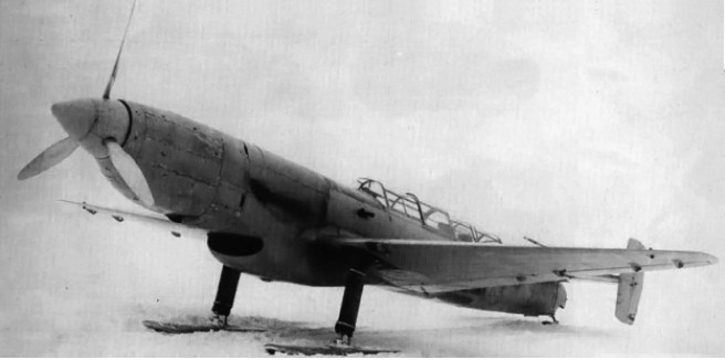
The Sparka was reconfigured for a single 960 hp (716 kW) Klimov M-105P (some say 103P) engine, which was installed in the forward engine bay. The M-105P was a development of the M-103P; both had a smaller bore of 5.83 in (148 mm), but the stroke was unchanged, and could be fitted with a cannon to fire through the engine’s Vee. The aircraft was tested on skis in early 1942 but was underpowered with the single M-105P, attaining a top speed of 249 mph (400 km/h).
Development on the Sparka was abandoned in mid-1941, partially a result of the German invasion. In addition, the factory where the Sparka was built was needed to produce the Petlyakov Pe-2 attack bomber.
I-1 Modification
Engine Type 2 PD-107 AM
Power,
maximal 2 x 1400 HP
rated at 2 x 1250 HP
Wingspan: 13.80 m
Length: 12.96 m
Wing area: 22.90 sq.m
Empty weight: 2560 kg
Maximum take-off weight: 4810 kg
Maximum speed SL: 640 km / h
Maximum speed: 750 km / h
Range: 2000 km
Rate of climb: 1000 m / min
Service ceiling: 10,000 m
Crew: 2
Armament:
two 23-mm cannon and four BR 12.7-mm machine gun BS
two to four bombs caliber from 100 kg to 250 kg.
S-2M-103 Sparka
Engines: two Klimov M-103, 960 hp (716 kW)
Prop: six-blade, coaxial contra-rotating
Wingspan: 37 ft 4 in (11.38 m)
Length: 43 ft 4 in (13.2 m)
Weight: 12,460 lb (5,652 kg)
Bomb load: 882 lb (400 kg)
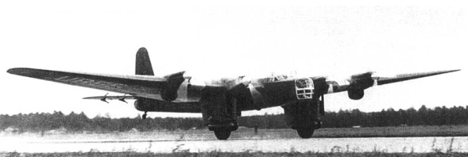
At the beginning of 1933 it became necessary to find a replacement for the aging Túpolev TB-3 bomber, which formed the basis of the long-range bomber aviation of the RKKA VVS. At the same time it became known that a group of professors and assistants from the Zhukovski Military Aeronautical Academy had been working on the conception of a new giant 12-engine bomber known as “Gigant”. By 1934 the need for an aircraft of these proportions had waned, so the financing of the project was cancelled. It was proposed to this group to develop a capital reconstruction project for TB-3.
Viktor Fedorovich Bolkhovitinov became the head of the VVIA design group at the VVA Žukovskij (VVS academy Žukovskij ) tasked with the design of a replacement for the Tupolev TB-3 heavy bomber. It was decided to study in depth the limitations of TB-3 and propose solutions to improve them. To this end, consultation work was started directly with the builders of Factory No.22 in Fili , where the Túpolev bomber was produced.
The new aircraft was designed as a Long Range Bomber or BDD (Russian: бомбардировщик дальнего действия – БДД). The technical tasks approved by the VVS for the new bomber in December 1934 included a speed of 320 km / h, a landing speed of 90-95 km / h, a flight ceiling of 6000 – 7000 m and a transport capacity of 1000 kg of bombs at a distance of 4000 km (with a total load capacity of 5000 kg). For its projection, a Joint Projection Bureau (OPB) was created, made up of technologists and builders from the factory and designers from the Zhukovski Academy.
The proposals put forward by the Academy were supported by RKKA chief of armament M. N. Tukhachevsky.
The Academy’s group of specialists conceived that, maintaining the tooling of Factory No.22, it was entirely possible to create an aircraft capable of meeting the specifications of the VVS and even in some cases exceeding them.
Soon Bolkhovitinov’s brigade was transferred to Factory No.22 in Fili, where the KB-22 was organized. Already participated in the projection of the new model. M. Kuritskies, IF Florov, BE Chertok, MM Shishmariov, among others.
The factory name for the new model was “A”. The Commission analysis of the model met on 14 January 1935, leaving some constructive recommendations for changes, the composition of the weaponry and equipment. By this time it was clear that even when the dimensions and composition were maintained constructively, it was a new aircraft. Despite this, it is remarkable that many official documents of the time refer to the new model as “the last modification of the TB-3 ” or “the TB-3 of 1935 “.
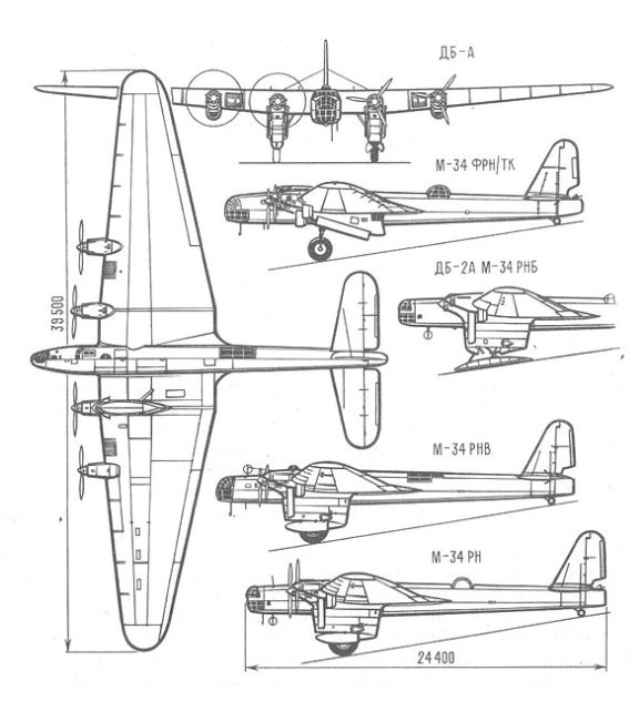
The resulting Bolkhovitinov DB-a (Russian: Болховитинов ДБ-А. Its acronym comes from the term Long Distance Bomber – Academy, Russian: Дальний Бомбардировщик – Академия) was advanced for its day with stressed skin aluminium alloy construction throughout with clean lines, neatly cowled engines and trousered main undercarriage legs, with fully retracting main-wheels and tail-wheel. The split flaps, undercarriage, nose turret and bomb-bay doors were all operated by a pneumatic system re-charged by engine driven compressors.
Upgraded bombs with 6 x 2 m hatches, mechanized and armoured Tur-8 turret and closed cockpits for the crew (with the exception of the tail gunner).
The new fuselage with a monocoque structure made it possible to significantly increase the interior volume of the aircraft. In the lower part of the center was located the bomb bay with a capacity for 3000 kg of bombs in the following configurations:
8 bombs of 250 kg;
6 bombs of 500 kg;
2 bombs of 1000 kg;
or 24 bombs of 100 kg.
The ability to install VAP-500 and VAP-1000 external supports, as well as a rotary launching system for RRAB pumps, was envisaged.
In the nose there was a Tur-8 turret with a ShKAS machine gun, which rotated with the help of a pressurized air system and in the central area of the fuselage a Tur-Aldis turret, designed in the TsAGI, with a ShVAK 20mm cannon. To defend the belly area, a ShKAS machine gun was installed firing through a hatch. In the tail area, the installation of a TUR-8 turret with another ShKAS machine gun was planned. The cannon had 250 rounds, while the total ammunition load for the machine guns reached 3,000 units.
The wing had a structure with three spars and a TsAGI – 620 profile. It was made up of the centrewing and two wing consoles. Nine fuel tanks accommodated 14,600 liters and two 460-liter oil tanks were located in the wing between the engines. In the intrados the underwing supports were located with a total capacity of 2000 kg of pumps. Both the flaps and the ailerons had a metallic structure and textile covering. The use of these flaps, capable of operating at 60º, allowed the landing speed to be reduced to 80 km / h.
The operation of the flaps, the retraction and extension of the wheels, the turning of the bow turret and the opening and closing of the hold gates were carried out by means of a pneumatic system.
The DB-A incorporated an APR-3 radio-rangefinder. The project also included the addition of an AVP-10 autopilot system. Both crew members communicated with the help of an intercom system. For night landings, the placement of headlights under the wings was foreseen.
The power plant consisted of four M-34RN engines. The project was calculated for the turboed version M-34FRN, but this model became available later.
The landing gear was designed as a conventional type with a tail wheel. The main units featured 2000x450mm wheels that partially retracted into large ‘pant’ type fairings. To allow the exploitation of the aircraft in winter operations, the use of special skis was envisaged, but these were never built, so for the factory tests the skis of a TB-3 were used. The main landers used telescopic, hydro-pneumatic shock absorbers.
The DB-A crew of nine were two pilots, a navigator, two engineers, a radio operator – gunner and three other gunners, but in different configurations it varied between 6 and 9 people.
In November 1934 the construction of the first copy of the DB-A (Dalni Bombardirovchik – Akademia or Long-range Bombardment of the Academy) was completed. Instead of the M-34FRN engines required by the project, four M-34RNs with a lower power were installed in the new prototype.
Flight trials began on 2 May 1935 at Khodinka piloted by factory pilots N.G. Kastanyev and Ya.N. Moseyev, Later, due to Moiseyev’s illness, he was replaced by AK Tumansky, brother of the aircraft engine manufacturer Sergei Konstantinovich Tumansky . The crew also included engineers Godovikov, Florov, Konkin and Osipienko.The first flight of the new “22A” factory index bomber lasted barely half an hour, but it demonstrated the value of the technical solutions applied to the “Annushka” (Anita) as the workers of Factory No.22 where it was developed called it.
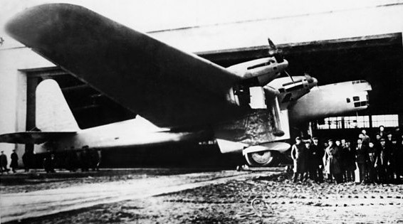
Initially, the DB-A engines had wooden propellers with two blades and a diameter of 4.35 m, similar to those used in the TB-3, but this brought about a noticeable decrease in performance in relation to those calculated, therefore It was decided to replace them with one of three 4.1 meter blades, similar to those used in the Túpolev ANT-25.
Factory tests were completed by April 1934 and NII testing was carried out in May and June 1935. In them it was shown that the DB-A out-performed not only the TB-3, but even the Farman-222 with a similar mission. Despite presenting an empty weight 15.4 tonnes higher than that of the TB-3, the DB-A showed an increase in speed of 40 – 50 km / h. This increase in performance was mainly due to the aerodynamic improvement of the model. With retraction of the landing gear, 18-20 km / h were gained at sea level and 25-28 km / h at 2000 meters. The performance demonstrated included, sustained flight at an altitude of 2,500m (8,202 ft) with two engines shut down, and 4,500 km range.
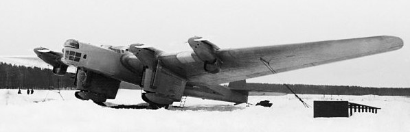
The aircraft assessment report only included poor visibility from the cockpit as a defect. However subsequent investigations have shown that the report was not objective. There is evidence of contradictions between Kastanayev and Tumanski, as the former eliminated the defects from the reports in order to get the plane to be chosen for the long-haul flight to the United States proposed by the polar pilot SA Levanevski.
The aircraft was shown to Levanevski and government approval was soon received to prepare the first factory specimen No.22-A1 for flight, assigning it the USSR-N-209 polar aviation index.
In 1936 the DB-A was shown in the parade commemorating the first of May, causing a sensation among national and foreign guests.
A decision was made to fly non-stop from Moscow to the USA and the DB-A was modified to fly, at an overload weight of 34,700 kg (76,500 lb), carry enough fuel to fly 8,440 km (5,244 miles). While the state tests were being carried out, the first DB-A was modified and prepared for the record flight on the Moscow – North Pole – Fairbanks route. The plane was lightened. All weapons were removed; the glazing of the forward cabin in which the navigator and radio operator were located was modified; an astrological dome was installed over the pilot’s seat, the position of the tail gunner was removed. The weight saved went to a new fuel tank and commercial cargo.
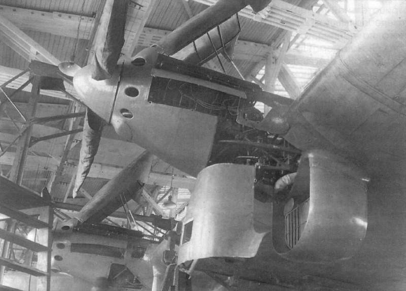
During the preparation of the flight, a test flight was carried out on the Shelkovo – Baku – Shelkovo route and a test takeoff with a weight of 32,300 kg.
The flight across the North Pole on the red painted DB-A prototype USSR-N-209 began on August 12, 1937 from Moscow Shchyelkovo airport on an attempt to fly to Fairbanks, Alaska. The crew consisted of SA Levanevski as pilot and captain, NG Kastanayev as second pilot, VI Lievchenko as navigator, mechanics GT Pobratimov and NN Godovikov and radio operator N. Ya. Galkovski.
Although the weather conditions on the route were extremely difficult, it was decided to continue the flight. On August 13 at 1:40 p.m. Moscow time, the crossing over the North Pole was reported. At 14:32 the last radio communication was received informing that an engine had stopped. Then the link was lost. The plane was never found, despite intensive searches carried out for almost a year. In more recent times, attempts have been made to continue searching using more advanced search techniques, without obtaining any results.
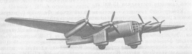
In order to verify the performance obtained during the prototype factory tests, it was decided to deliver the second prototype, known as DB-2A, to the NII VVS to carry out the state tests, which began on March 14, 1936. This model was equipped with a more powerful version of the M-34RN engine rated at 1000 hp and a new radiator.
The main pilot for the tests was MA Nyuxtikov and the principal engineer Losiukov. The flight results set in these tests were:
Maximum speed at sea level: 280 km / h
Maximum speed at 3000 meters: 323.5 km / h
Maximum speed 4200 meters: 330 km / h
Landing speed: 80 – 85 km / h
Practical ceiling with weight of 21,600 kg: 7,220 m
Take-off run: 300 – 350 m
The evaluation report of the state tests, signed by the head of the VVS Ya. I. Alksnis on June 1, 1936 concluded: “Compared to the TB-3 4M-34RN aircraft, the DB-2A prototype presents the following improvements: 1 – Considerable increase in horizontal speed. With the use of M-34FRN engines for which it was calculated, the speed should be increased until reaching 360 – 370 km / h. 2 – The large capacity of the fuel and oil tanks, at the overloads for which the aircraft was calculated, guarantee a great range. ” But there were a series of defects whose enumeration reached 38 points. Among them:
1 – Unsatisfactory stability and handling;
2 – Low effectiveness of the ailerons and great pressure on the lever during its operation;
3 – Low effectiveness of the rudder and great pressure on the lever during its operation;
4 – In flight regime between atmospheric turbulence, the effectiveness of the tail decreases significantly with rolling. A prolonged flight in these conditions is made impossible by the pilot’s fatigue.
5 – Appearance of strong vibrations in the tail unit in some flight regimes.
Despite not being included in the official report, Tumansky had highlighted other defects, including the impossibility of completing the oil capacity in flight, the inability to use the last 60 kg of oil in the tanks, due to the location of the system nozzles. Piloting the plane required great physical strength and there was no oxygen system for the crew.
Several improvements were made to the aircraft that included modifications to the aileron and rudder control systems. The appearance of strong vibrations in the tail section forced a flight weight limit of 21,800 kg to be established. Upon learning of this, Boljovitinov himself together with the test pilot MA Nyuxtikov conducted a test flight, managing to find a weak point in the aircraft’s structure, which was soon reinforced. With this it was possible to raise the takeoff weight to more than 30,000 kg.
The DB-A was flight tested with only three engines. In this case the maximum speed decreased to 292 km / h, the ceiling with 21,500 kg of weight reached 5100 meters. It is noteworthy that in the tests an engine was never really disconnected, but the power was reduced to the maximum. With two engines working, the plane was unable to exceed 2,500 meters in height.
In the flight tests there were several mishaps that luckily did not end in disasters:
On March 11, at an altitude of 2000 m, due to a power failure during the climb, the four engines stopped and only the quick action of the pilots who managed to stabilize the horizontal flight, guaranteeing the necessary flow of fuel to the engines. was able to avoid an accident.
On May 21, 1936, during landing 67 and due to a manufacturing defect, the left leg of the landing gear broke.
In June 1936, installation tests were carried out on the DB-2A of the M-34FRN engines with take-off power of 1220 – 1240 hp and new metal propellers. It was decided to develop a new test suite on the NII VVS. These tests were developed by the third rank military engineer MA Lipkin and had MA Nyuxtikov as the main pilot.
The M-34FRN engines (with factory numbers № 436, 437, 4311, 4314) were experimental and did not pass the test because they were considered unreliable. Compared to the M-34RN they had a power increase of only 50 – 70 hp. It was impossible to install them on the plane until its completion by Factory No.24.
In the report of the test results with the new powerplant signed by the head of the VVS Ya. I. Alksnis on November 2, 1936 it is found that:
“… The installation of the M-34FRN engines in the DB-A aircraft, due to its low working height and lack of completion, negatively influenced the flight data of the aircraft, excluding the speed performance (maximum speed grew at 10 km / h)”.
In the conclusions of the state tests Alksnis also wrote:
“Taking into account that the DB-A significantly surpasses the TB-3-4M-34RN in performance and that the defects indicated in the state tests can be solved during the construction of the field series, consider it essential to begin preparation for production series of these aircraft based on the results of field tests”.
In 1936 itself, the process of preparation for serial production began. At that time a contradiction was created between Bolkhovitinov and the director of Factory No.22, Tarasievich. The factory had been instructed to restore production of the TB-3 and a large production plan for SB bombers. On the other hand, Túpolev had begun to propagandize the series production of his TB-7. For this reason, Tarasievich submitted to Glavaviaprom (of which Tupolev was deputy chief engineer) the request to develop the production of DB-A in Kazan, at Factory No.124. This request soon became a decision sanctioned by the Commissariat for Heavy Industry.
This decision directly affected the group. Bolkhovitinov could not refuse to move, as this meant refusing to produce the bomber. KB members received the documents for a lengthy service commission. Several specialists were unable to transfer and others simply did not want to do so, for example Kuritskies and Shishmariov, who taught at the Academy, decided not to leave the VVA.
Only two complete copies had been built at Factory No.22: the DB-A prototype and the second DB-2A. A third uncompleted specimen was sent to Factory No.124 in Kazan for completion. As a basis for serial production it would be necessary to build 4 or 5 aircraft, which were to be produced at Factory No.22.
Although initially it was planned to have the first copy ready for December 1936, the construction of the plane was delayed. At the beginning of 1937 all the forces of Factory No.22 focused on the first copy in order to be able to deliver it for testing on February 8.
In April 1937, joint tests began with the contractor of the first specimen intended for field tests, produced at Factory No.22. This aircraft was a modified DB-2A. Among the main differences was the fully retractable landing gear. Initially 1350×300 mm wheels were selected but it was shown that they did not support the maximum flying weight of the aircraft, so other 1600×500 mm wheels were chosen. The cockpits for the pilots, navigator and mechanics had been totally modified and raised to improve visibility. This caused the deck to protrude from the fuselage, ending in a fall in which it was thought to locate a ShKAS machine gun.
On the nose was the two machine gun system used in the SB. In the central region there was a turret with a ShVAK cannon that rotated with the help of an electric motor. The initial turret, now equipped with a PMP-2 collimator, was kept in the tail.
This new specimen received the name DBA-37 or simply DB. The test brigade was made up of the test pilot MA Nyuxtikov, the second pilot and engineer Antojin, the armament engineer Stvietkov and the chief engineer of Factory No.124 Volkov.
As a result of the second stage of testing, the surface and trim area of the rudder was increased. Later, the construction of the cellar hatch opening system was changed, the engine exhaust system was modified, the trimmers and the aileron and rudder compensation system were modified, among other minor changes. For crew communication, a new intercom system SPU-1 was adopted and RSTB-1 and RSB radios were added. The crew grew to 11 people. The changes continued until the end of 1937.
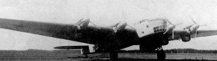
The first modernized DB-A copy was completed only for the month of May. Factory tests with M-34RNV engines took place between May 11, 1937 and March 22, 1938. The test brigade in this case consisted of the test pilot MA Nyuxtikov, the second pilot and engineer Antojin, the chief engineer of Factory No.22 Frolov and the engineer of Factory No.124 Garanovich.

Compared to the first copy, the handling worsened. With respect to the first prototype, the take-off weight had increased by 2000 kg and the maximum speed to 3000 meters was increased by only 8 km / h, so the modifications had been insignificant.
The long duration of the tests was due to the fact that, after the disappearance of Levianevski, the works in the DB-A were stopped and only continued in early 1938.
The first stage of state testing of the modernized DB-A took place between October 21 and December 20, 1937. After several modifications to the aircraft, the tests were continued at the NII VVS between April 14 and June 24, 1938. The final result of the tests was generally positive, for which the series production of 16 copies was authorized.
Between August 26 and September 28, tests were carried out with the M-34FRN engines with turbochargers and VISH-3B propellers of 3.9 m diameter. The tests were carried out in conjunction with the NII VVS. A total of 13 flights were carried out, of which 6 were carried out at altitudes of more than 9000 meters. They aspired to reach 11,000 meters, but the poor work of the compressors did not allow this result to be achieved. With this new power plant, the empty weight of the aircraft grew by 910 kg, reaching 17,722 kg. The takeoff weight was close to 24 tons.
Only 12 copies had been built by the end of 1939, when production was halted in favour of the Túpolev TB-7. The built specimens were destined for the 5th Long Range Bomber Aviation Corps of the RKKA VVS in the Far East. In 1940 there were 6 DB-A bombers in service there. At the beginning of the war these aircraft were not transferred to the European region of the USSR, serving basically as transports until the end of their useful life.
In 1940 the problems presented with the production of the TB-7 brought to the table for discussions the issue of restoring the production of the DB-A, but from there it did not happen.
Among the possible development variants to eliminate the problems of the use of a lower performance powertrain than the projected one, the use of Charomsky AN-1 diesel engines was valued.
Records:
The 10 November of 1935 pilots MA Nyuxtikov and MA Lipkin set a new world record for the lifting 10 tons of weight to 7,032 meters high.
On 20 November 1935 these pilots set a new record holder for the lifting 13 tons to 4,535 meters.
The 14 May 1937 pilots GF Baydukov. NG Kashtanayev and LL Kerber flew in a DB-A on the Moscow – Melitopol – Moscow route covering 2002.6 km in 7 hours 2 minutes and 11 seconds with a payload of 5 tons. Two world records were set on this flight:
Speed of 280 km / h in distance of 1000 km with 5 tons of load.
Speed of 246 km / h in distance of 2000 km with 5 tons of load.
Variants:
DB-A – The initial prototype aircraft, with M-34RN engines, lost on a non stop flight Moscow to Fairbanks, Alaska.
DB-2A – The second prototype with many detail improvements and M-34RNV engines.
DBA – Production aircraft ordered in 1937. Sixteen aircraft ordered, but only twelve completed, with M-34FRN engines plus turbo-chargers, rearwards retracting main undercarriage, gunners cockpits in the rear of the inner engine nacelles, and other modificatoions.
TK-1 TK ( – heavy cruiser) – Projected escort bomber with 11 crew, 3xShVAK + 3,000 rounds, 5xShKAS + 11,000 rounds and underwing rockets.
Specifications:
DBA
Engines: 4 × M-34FRN + turbo-chargers, 970 hp
Wingspan: 39.5 m (129 ft 7 in)
Wing area: 230 sq.m (2,476 sq.ft)
Length: 24.4 m (80 ft 0-5/8 in)
Stabilizer wingspan: 12.5 m
Height: 8.50 m
Wheelbase: 7,690 m
Empty weight: 16,150 kg (35,605 lb)
Gross weight: 22,000 kg (48,500 lb)
Power load: 5.7kg / hp
Wing loading: 95 kg / m²
Maximum speed: 316 km/h (196.4 mph)
Maximum speed at 4000 m: 330 km / h
Cruising speed: 260 km / h
Range: 4500 km (2,796 miles)
Service ceiling: 7,730 m (25,360 ft)
ROC: 135 m / min
Climb to 1000 m: 5 min
Climb to 7000 m: 56 min
Crew: 6 – 9
Armament:
2 x ShKAS 7.62mm machine-guns in each of the inner nacelle gun positions.
1 x ShKAS 7.62mm machine-guns in nose and tail positions.
1 x ShVAK 20mm cannon in the dorsal turret.
5,000 kg of bombs in internal bomb-bay.