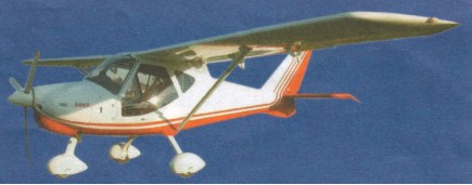
H M Daily
Chicago IL.
USA
Circa 1910 airplane builder
H M Daily
Chicago IL.
USA
Circa 1910 airplane builder
A lead in fighter trainer/light combat aircraft.
A turboprop trainer.
South Korea
Aerospace division founded 1984. Programs include development and production of the KTX-1 Woong- Bee turboprop trainer, work on F-16 construction and KTX- 2 lead in fighter trainer/light combat aircraft programs under Samsung leadership, component production for commercial transports, and helicopter and UAV programs.
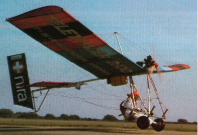
Single seat single engined high wing mono¬plane with hybrid control. Wing has unswept leading and trailing edges, and constant chord; cruciform tail. Pitch control by elevator on tail; yaw control by fully flying rudder; no separate roll control; control inputs through weight shift for pitch/yaw/roll. Wing braced from above by kingpost and cables, from below by cables; wing profile 100% double surface. Undercarriage has two wheels with tailskid. Aluminium tube framework, without pod. Engine mounted at wing height driving tractor propeller.
The Daedalus Apex 2, is similar in concept to the Quicksilver E, in that it uses weight shift allied to a rudder and elevator to give hybrid control, a formula which is popular in North America but unusual in Europe.
The obvious difference between the Apex 2 and the Eipper product, however, is the choice of power unit and the use of a tractor propeller. Marco uses the Konig SC430 three cylinder radial engine, allied to a three blade propeller, a combination which has proved highly effective. Not only has Marco flown extensively in the Alps with the Apex 2, but he also competed in the 1982 London Paris, where he got a special award for having the quietest aircraft in the competition.
Engine: Konig SC430, 24 hp.
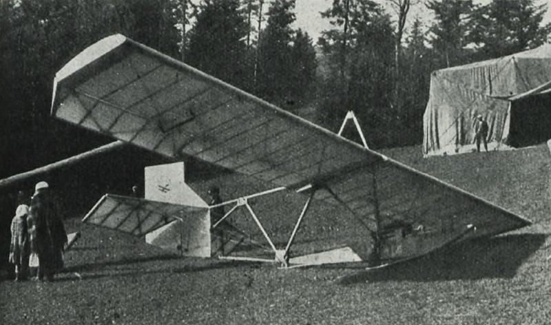
ZASPL, the Aviation Association of students of the Lwów Technical University, was the oldest aviation organization in Poland. Revived after World War I, by 1926 it had workshops in Lwów which began building the glider designs of ZASPL member Wacław Czerwiński. The successful Czerwiński CW III, a 1929 open frame introductory glider, had shown the utility of the type for basic training but it was expensive and ready for development. In response, Czerwiński and Władysław Jarworski designed the CWJ (a fusion of their initials) to fill the national gliding clubs’ needs.
The fuselage of the CWJ was essentially an uncovered pine Warren girder, though the rear part of the lower longeron or chord was upward-curved. The unprotected pilot’s seat was forward of the wing on a pine fuselage box which reached back to about mid fuselage. The box also carried twin sprung landing skids. The CWJ’s two part, twin spar wing was rectangular in plan. Mounted on the upper fuselage longeron, it was wire braced from above via an inverted-V cabane and from below to the lower longeron. Short ailerons reached the tips.
At the rear a broad fin occupied the gap between the upper and lower longerons and had a short, triangular extension above. An almost rectangular rudder ran upwards from the bottom of the fin, extending well above it. The tailplane, mounted on the upper longeron, was triangular in plan. It carried elevators which were rectangular apart from cut-outs for rudder movement.
The CWJ first flew in October 1931, tow-launched by a car.
An improved version, the CWJ-bis Skaut (Scout) made its first flight on 3 August 1933 at Czerwony Kamień, the base of the Lwów Aeroclub Gliding School. It had a wing increased in span by 900 mm (35 in), a corresponding 11% increase in wing area and had washout at the wingtips which improved aileron response. The wire wing bracing of the CWJ was replaced by pairs of parallel struts and the fuselage box was strengthened. The empennage was also modified; the fin now had a triangular, rather than straight, leading edge and at some later time the top of the rudder was made almost semi-circular. A few had ply-covered cockpits. Early tests showed the sought-after improvement in handling.
Shortly after its successful early tests, early orders from both the government and LOPP took the CWJ into production. Design drawings were also produced for amateur builders and some parts and materials were made available from ZAPL. According to Cynk about eighty examples of the CWJ and CWJ-bis were built in all, including about twenty of the latter, though samalotypolskie.pl says that there were one hundred altogether, eighty of them CWJs. They were used by clubs across Poland and were easy to transport, tough, could be car-launched and were stable in flight though with limited performance. By about 1938 both variants had been retired, displaced by the newer, better performing Kocjan Czajka and Kocjan Wrona.
CWJ
Wingspan: 8.75 m (28 ft 8 in)
Wing area: 13 m2 (140 sq ft)
Length: 5.59 m (18 ft 4 in)
Height: 2.21 m (7 ft 3 in)
Empty weight: 80 kg (176 lb)
Gross weight: 150 kg (331 lb)
Stall speed: 42 km/h (26 mph, 23 kn) minimum speed
Maximum glide ratio: 12 maximum at 50 km/h (31 mph; 27 kn)
Rate of sink: 1.3 m/s (260 ft/min) minimum
Crew: One
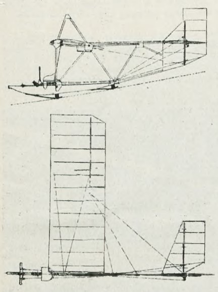
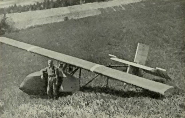
ZASPL, the Aviation Association of students of the Lwów Technical University, was the oldest aviation organization in Poland. Revived after World War I, by 1926 it had workshops in Lwów which began building the glider designs of ZASPL member Wacław Czerwiński. The second and third of these, the CW II and CW III, were both built there during 1929. Both were high wing, wooden, open frame gliders, though only the CW II had a nacelle enclosing the pilot’s cockpit.
The CW II (also known as CW-02) had a rectangular plan, single spar wing, with plywood covering forward of the spar and aircraft fabric covering elsewhere, which was built in three parts, a half-span wide centre-section and two outer panels with trailing edges filled with ailerons. The centre-section was mounted just above the upper longeron, or chord, of the flat girder fuselage on four outward leaning inverted-V struts. Wire bracing from the lower longerons to the outer ends of the centre-section carried lift loads. The longerons were straight, parallel and cross-braced with alternate vertical and diagonal cross-members. The lower longeron extended forward of the wing and carried a plywood nacelle with an open cockpit; the nacelle extended rearwards under the wing. Under it, a wooden landing skid was mounted on rubber shock absorbers. The empennage was conventional, with fabric-covered rectangular surfaces. Its fin extended upwards from the lower longeron to just beyond the upper one, carrying the tailplane close above; a tall, balanced rudder operated in a cut-out between balanced elevators.
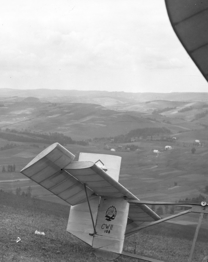
In 1929 Greszczyk made the first, brief flights of both the CW II and CW III, towed behind a car. In the autumn of 1929 they were taken to Bezmiechowa Górna for pilot training. Over fifty flights were made, chiefly on the better-handling CW III, but on 2 November Greszczyk set a new national gliding duration record of 2:11:4.5 hours in the CW II. In the following spring they returned to Bezmiechowa with some thirteen novices, including the first two female Polish glider pilots, Danuta Sikorzaanka and Wanda Olszewskz. The CW III was used as a basic trainer, with the CW II reserved for the more experienced.
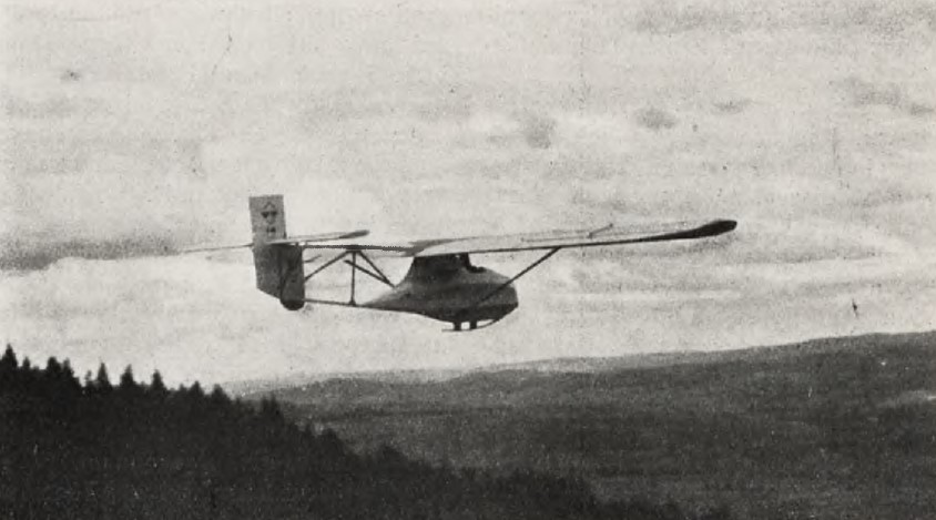
In 1930 ZASPL began a short production run of the CW III (also known as CW-03), an improved version of the CW II also first flown in 1929, making it the first Polish glider to go into production. A few more were amateur built and overall as many as twenty were completed. The chief difference between it and the CW II was a new, two-part, rectangular plan wing with Gôttingen Gô 365 section. This had a lower aspect ratio of 5.9, with a reduced span but increased area. There was no nacelle, with the pilot exposed on a lowered seat. It proved easier to fly than the higher-performing CW II and well suited for its intended basic training role.
After successful operation between 1929 and 1931, the sole CW-II was considerably modified during the winter of 1931-2. It received a new, two part centre-section which was attached directly to the upper longeron and braced with a single strut on each side to the lower longeron. The wingtips were altered in plan from rectangular to curved, reducing the wing area by 3%, and the nacelle was better streamlined. These changes significantly improved the best glide ratio, though values given by various references differ.
From 1930 many Polish pilots learned to fly on the production CW IIIs, though these were soon joined and then supplanted by a 1931 CW II development, the simpler and cheaper CWJ. The last CW IIIs were withdrawn from service in 1938.
Variants:
CW II
Built in parallel with CW III, completed 1929. Open frame glider with pilot’s nacelle.
CW IIbis
CW II revised in 1931-2 with a reduced area wing which had a new, strut braced, two part centre-section and rounded tips. Better aerodynamics and performance.
Wingspan: 11 m (36 ft 1 in)
Wing area: 18.1 sq.m (195 sq ft)
Aspect ratio: 6.7
Airfoil: Gôttingen Gô 535
Length: 6.25 m (20 ft 6 in)
Height: 1.75 m (5 ft 9 in)
Empty weight: 120 kg (265 lb)
Gross weight: 195 kg (430 lb)
Stall speed: 38 km/h (24 mph, 21 kn) minimum speed
Maximum glide ratio: 13 at 47 km/h (29 mph; 25 kn)
Rate of sink: 0.95 m/s (187 ft/min) at 44 km/h (27 mph; 24 kn)
Crew: One
CW III
Built in parallel with CW II, completed 1929, it was similar to the Cw II but lighter, with no pilot’s nacelle, a different wing of lower aspect ratio and a different airfoil. It had lower performance than the CW II but was easier for novices to fly. Limited production from ZAPL and some amateur builds together provided about twenty airframes; it was the first Polish glider to reach production.
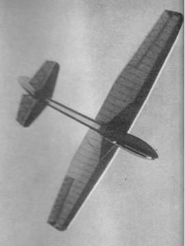
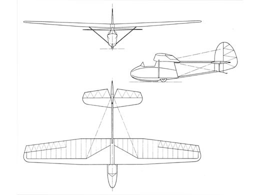
In the early years of World War II there was little gliding activity in Canada. Feeling that a Gliding Club would be well received by the military, and with the approval of their employers, some staff at the de Havilland Aircraft Company of Canada decided to form their own. The initiative was taken by Wacław Czerwinski who went on to lead the design of the group’s own glider, a very close copy of the W.W.S.1 Salamandra which Czerwiński had designed before the war in Poland. Members of the drawing office worked in their own time to produce the engineering blueprints, de Havilland and other companies took an interest, assisting the project with donations of instruments and a landing wheel.
The design aim was to produce an aircraft which could be used both as basic trainer (primary glider) and as a sailplane capable of exploiting the strong thermals of the Toronto region. The docile handling of a typical primary glider, particularly in the stall, had to be maintained alongside a better lift to drag performance than most of that class.
It was a high wing aircraft, with a single spar wing with rounded tips, straight taper on the outer ⅔ of the span and a constant chord centre section. The wings were ply covered from the leading edge to the main spar and fabric covered aft. The wings carried some dihedral and there was washout, a decrease in angle of incidence outwards along the span, on the outer panels to avoid spin initiation at the stall. Generous differential ailerons, also fabric covered, ran from the wingtips over most of the outer, tapered panels. The wing was mounted on a fuselage pedestal above and immediately behind the cockpit in the flat sided forward fuselage. Though open, this cockpit enclosed the pilot as in a light aircraft, rather than leaving him fully exposed as on many earlier primary gliders. A pair of lift struts joined the main spar to the lower fuselage longerons.
Behind the wing trailing edge the enclosed fuselage was replaced by a pair of nearly horizontal beams, one vertically above the other, which carried the tail unit. The ply-covered tailplane and fabric covered elevators were mounted on the upper fuselage beam. Fin and rudder, ply and fabric covered respectively, continued down below the horizontal surfaces to the lower beam, the rudder moving in an elevator cut-out. Like the wing, the tailplane was strut braced from below. The rear surfaces were braced against lateral deflections by pairs of wires from the upper wing surfaces to the top of the fin and by similar wires from below to its bottom.
The undercarriage consisted of a keel skid which ended about midway below the wing, where a single wheel was partially exposed. There was a tailskid and wire loops at the wing tips to protect them and ease ground handling.
The Czerwiński Sparrow, sometimes known as the de Havilland Canada glider, flew for the first time in late August or early September 1942, aero-towed by a Tiger Moth. Released at 1,380 ft (420 m), it reached an altitude of 5,800 ft (1,770 m) during a 2 hr test flight.
The Sparrow was operated by the de Havilland Glider Club at Downsview, Ontario, initially without a registration, being registered as CF-ZAI on 10 June 1947. In 1948 it was donated to the Toronto Gliding Club, and was wrecked in an accident at Oshawa Airport on 4 June 1950.
The Czerwiński Robin was an improved version of the Sparrow.
Czerwiński Robin
Wingspan: 11.35 m (37 ft 3 in)
Wing area: 15.68 m2 (168.8 sq ft)
Aspect ratio: 8.2
Airfoil: Sikorski G.S.1
Length: 5.8 m (19 ft 0 in)
Empty weight: 120 kg (265 lb)
Gross weight: 214 kg (472 lb)
Stall speed: 41 km/h (25 mph, 22 kn)
Never exceed speed: 161 km/h (100 mph, 87 kn)
Rough air speed max: 161 km/h (100.0 mph; 86.9 kn)
Aerotow speed: 161 km/h (100.0 mph; 86.9 kn)
Winch launch speed: 93.8 km/h (58.3 mph; 50.6 kn)
Maximum glide ratio: 16.4 at 55 km/h (34.2 mph; 29.7 kn)
Rate of sink: 0.823 m/s (162.0 ft/min) at 51.4 km/h (31.9 mph; 27.8 kn)
Wing loading: 13.65 kg/m2 (2.80 lb/sq ft)
Crew: 1
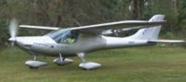
The all-metal Parrot is the first LSA to offer a full-cantilever metal wing, a glass shape in real metal, a forward-hinged canopy, and plenty of payload. Flight tests on the new machine have exceeded expectations. The entire design effort was built around the Sport Pilot (LSA) rules. Designed from the ground up for the American rules and the American market; and uses American-sourced materials, optimized performance to the LSA rules. Its efficient airfoil, developed on high-performance sailplanes, is a key feature unmatched in the industry. The smooth shape, made possible by the Parrots proprietary construction fixtures, also contributes to the quiet ride. With a shape usually considered achievable only on composite aircraft, the Parrots stretch formed and hydroformed panels blend together with flush rivets to give the appearance of composite, with standard full-interior zinc chromate protection on the ready-to-fly machine.
Stall: 30 kt / 35 mph / 56 kmh
Cruise: 113 kt / 130 mph / 209 kmh
VNE: 137 kt / 157 mph / 253 kmh
Empty Weight: 360 kg / 793 lbs
MTOW Weight: 599 kg / 1320 lbs
Climb Ratio: 1000 ft/min / 5 m/s
Take-off distance (50ft obstacle): 750 ft / 229 m
Landing distance (50ft obstacle): 400 ft / 122 m