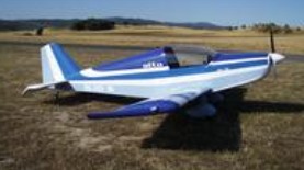
Direct Fly Alto

The Alto aircraft is an all-metal construction aircraft for amateur construction. The Alto aircraft meets both requirements to European category “ultralight aircraft” and “light sport aircraft” (LSA) category that has been defined in the U.S.A.

Different versions were offered. A basic version with the tricycle, nose type landing gear or optional with the tail landing gear with Rotax 912 ULS/UL as standard, but Jabiru on request, and wheel-type control or the stick control, standard is wheel control

Alto is single-engine, two-seat, low-wing, cantilever monoplane. The aircraft is all-metal riveted construction and may be equipped with rescue parachute system.
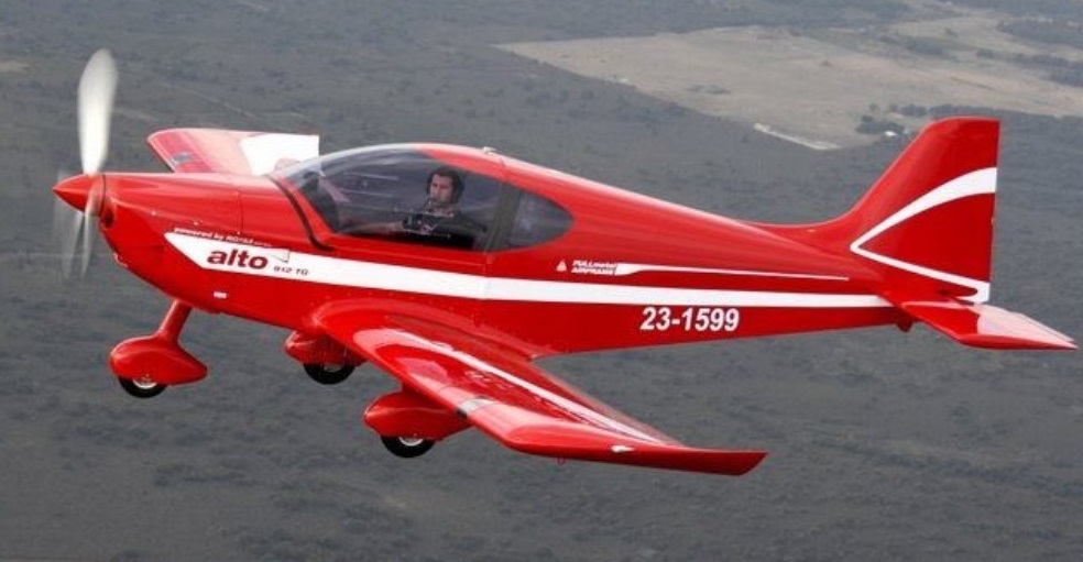
Alto 912 TG

The TG version (basic) is the tricycle, nose type with the nose landing gear steering. The main wheels are attached to the flexible all-composite legs. The main landing gear wheels brakes are operated by the hydraulic system, by means of break pedals (in the left side only) or with central brake with parking function. The TW version (optional) has the tail wheel landing gear.

The rectangular wing is a monospar construction with an auxiliary spar. The skin is made from duralumin sheet. The wing is equipped with ailerons, slotted flaps and integral fuel tanks with a total capacity of 105 l. All the parts are riveted together. The wing-body attachment forms a wing centre section, which is firmly placed into the fuselage. The wing main spar is connected to the wing centre section by bolts and the rear auxiliary spar is connected by a hinge.

The rectangular fuselage is of semimonocoque, riveted construction and has a bottom and the side walls reinforced by diagonal stiffeners. The dorsal is of oval cross section.

Alto 912 TG

The tail unit is of all-metal, riveted structure and has a standard configuration.

Aeroplane control consist of elevator, ailerons and rudder control surfaces. The manual control is of a wheel-type or a stick and deflections are transmitted by chains, push-pull tubes, and cables. The pedal control deflections are transmitted by cables to the rudder, and by push-pull tubes to the nose landing gear steering. The wing flaps and the elevator trim tabs are operated electrically. The main landing gear wheels brakes are independently operated by the hydraulic system, by means of break pedals on the pedal control.

The cockpit inner width is 106 cm and the wheel-type control and a forward sliding canopy make for easy boarding. The canopy is made from glass, and optionally may has light blue colour, and may be equipped with the wind-wings.

2009 Price: 44000 EURO

Alto TG 912 UL
Engine: Rotax 912UL, 80 hp
Length: 6,15 m / 20,18 ft
Wing span: 8,20 m / 26,9 ft
Wing area: 10,5 sq.m / 114 sq.ft
Height: 2,25 m / 7,38 ft
Cabin width: 1,10 m / 3,61 ft
Seats: 2
Fuel: 118 lt / 31,2 US gal
Take off run: 100 m / 328 ft
Landing run: 150 m / 492 ft
Empty weight: 280 kg / 618 lb
MTOW – ULM: 472 kg / 1041 lb
MTOW – LSA: 600 kg / 1320 lb
Vne: 255 km/h / 158 mph
Maximum speed: 230 km/h / 143 mph
Cruising speed: 185 km/h / 115 mph
Stall speed full flaps 450 kg: 65 km/h / 41 mph
Stall speed no flaps 600 kg: 81 km/h / 51 mph
G factor: +4 / -2
Climb rate 450 kg: 5,6 m/s / 1100 fpm
Climb rate 600 kg: 4,5 m/s / 890 fpm

Alto TG 912 ULS
Engine: Rotax 912ULS, 100 hp
Length: 6,15 m / 20,18 ft
Wing span: 8,20 m / 26,9 ft
Wing area: 10,5 sq.m / 114 sq.ft
Height: 2,25 m / 7,38 ft
Cabin width: 1,10 m / 3,61 ft
Seats: 2
Fuel: 118 lt / 31,2 US gal
Take off run: 90 m / 295 ft
Landing run: 150 m / 492 ft
Empty weight: 285 kg / 628 lb
MTOW – ULM: 472 kg / 1041 lb
MTOW – LSA: 600 kg / 1320 lb
Vne: 270 km/h / 168 mph
Maximum speed: 250 km/h/ 155 mph
Cruising speed: 200 km/h / 124 mph
Stall speed full flaps 450 kg: 65 km/h / 41 mph
Stall speed no flaps 600 kg: 81 km/h / 51 mph
G factor: +4 / -2
Climb rate 450 kg: 6,3 m/s / 1250 fpm
Climb rate 600 kg: 5,1 m/s / 1005 fpm
Take-off distance (50ft obstacle): 440 ft / 135 m
Landing distance (50ft obstacle): 490 ft / 150 m
Dinelli Aereoplano Glider

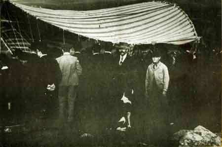
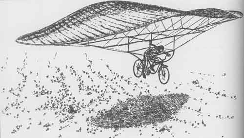
Guido Dinelli, an Italian shoemaker, was the second person in South America who is known to have made a gliding flight, while Pablo Suarez is believed to have been the first to do so. Both gliding flights took place at Tandil, Argentina, from atop Garibaldi Hill. Dinelli’s flight, on May 25, 1904, was made with a glider which he designed in late 1903. The glide was remarkable, covering 590 feet… a considerable distance.

Dinelli and his “Aereoplano apparatus” weighed a combined total of 211 pounds and was controlled by a number of ropes pulled by the operator. The glider, constructed of steam-bent spruce covered with cotton fabric, apparently was attached to a bicycle. Dinelli seems to have garnered some construction advice from Frank Brown, an English clown with the Carlo Brothers Circus. The wing was arranged to tilt (in order to vary the angle of incidence) so Dinelli could choose when to gain lift. He pedaled the bicycle to gain speed and then tilted the wing to lift just as he left the edge of Garibaldi Hill, timed to take advantage of an updraft. Dinelli’s glide, apparently his last, ended with damage to his glider and bruises to himself.

Dietrich / Dietrich-Gobiet

Richard Dietrich first built a monoplane at his Hanuske works in 1912, and learned to fly a year later. In 1922 produced the DP.1, one of the first light aircraft in Germany. About that time the name was changed to Dietrich-Gobiet, of Kassel. In 1924 built a cantilever biplane resembling a Fokker D.VII, as well as other designs, but by 1925 (when company reverted to original name) was in serious financial trouble, becoming bankrupt in 1927.

Diepen

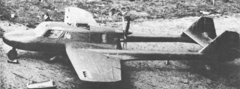
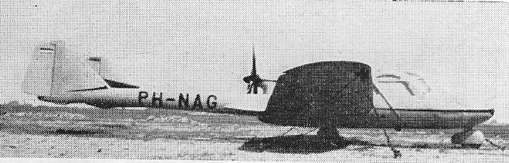
In 1946 Frits Diepen founded the Frits Diepen Aircraft Co Ltd, which was to deal with the sale, repair and overhaul of aircraft, the transport passengers by air taxis, publicity flightsand the running of Ypenburg Airfield.
On February 16th, 1954 Avio Diepen ¬became a subsidiary of Fokker

Diehl Aero-Nautical XTC

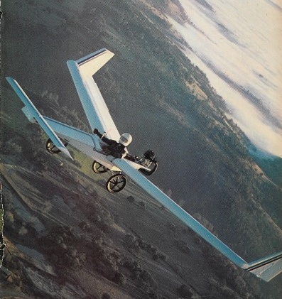
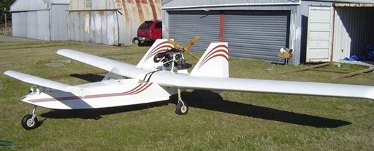
Single seat single engined mid wing monoplane with conventional three axis control. Wing has swept back leading edge, swept forward trailing edge, and tapering chord; two fin tail and canard wing. Pitch control by fully flying canard; yaw control by fin-mounted rudders; roll control by one third span spoilers; control inputs through stick for pitch/roll and pedals for yaw. Cantilever wing; wing profile double surface. Undercarriage has three retractable wheels in tricycle formation; steel spring suspension on all wheels. Push right go right nosewheel steering connected to yaw control. Individual brakes on main wheels. Glass fibre fuselage partially enclosed (total enclosure optional). Engine mounted above wing driving pusher propeller. Composite foam/glass fibre construction with spars in carbon fibre.

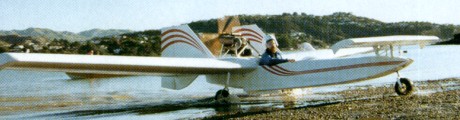
The appearance of the world’s first purpose designed amphibious ultralight created quite a stir when it appeared in prototype form at the ’82 Oshkosh and it has continued to attract great interest ever since.

This composite construction machine has floats at its wing tips and the entire fuselage forms a hull. The main wheels of the XTC Hydrolight retract sideways and outwards and the nosewheel retracts forward, nestling in the nose of the fuselage. Foot operated individual main wheels brakes are fitted.

Though originally fitted with a twin cylinder Cuyuna 430RR and later with the Kawasaki TA440 developing 39 hp at 6000 rpm, the XTC Hydrolight is now normally supplied with the KFM 107 engine. The title stands for Cross Terrain Craft and, according to its constructor, is pronounced ‘ecstasy’!
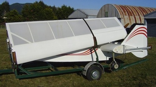
To allow trailer transport, the outer wing sections are removable, rigging time being quoted as 10 min with one person. The aircraft is supplied in kit form, requiring some 100 h for completion, for around $6000 in 1982, the exact price depending on the options selected from a long list including bubble canopy, parachute systems, lights, instruments, skis, Tedlar wing covering and a trailer.

Powered by a Rotax 447 it cruises at around 45-50mph at only 4700rpm and uses around eight litres per hour. You can up the cruise to 60-65mph. The hull is constructed of fibreglass and Kevlar, the wing has a fibreglass D-section leading edge and covered with sail cloth, and a carbon fibre capped spar. Wing attach fittings are titanium, and with extensive use of stainless steel and anodised aluminium in a majority of the rest of the metal fittings this is a very low maintenance airframe even if operated in the sea.

Gallery

Engine: KFM 107, 25 hp at 6280 rpm.
Propeller diameter and pitch 52×22 inch, 1.32×0.56m.
V belt reduction, ratio 2.1/1.
Max static thrust 170 lb, 77 kg.
Power per unit area 0.16 hp/sq.ft, 1.7 hp/sq.m.
Fuel capacity 5.0 US gal, 4.2 Imp gal, 18.9 litre.
Length overall 15.2 ft, 4.62 m.
Height overall 4.8ft, 1.44m.
Wing span 32.0ft, 9.75m.
Chord at root 5.0ft, 1.52m.
Chord at tip 3.0ft, 0.91m.
Dihedral 3 degs.
Canard span 12.0ft, 3.65m.
Canard chord 2.5 ft, 0.76 m.
Fin height 3.0 ft, 0.91 m.
Total wing area 155 sq.ft, 14.4 sq.m.
Main wing area 128 sq.ft, 11.9sq.m.
Canard area 27.0 sq.ft, 2.5 sq.m.
Total spoiler area 4.0 sq.ft, 0.37 sq.m.
Fin area 10.0ft , 0.93 sq.m.
Rudder area 8.0 sq.ft, 0.74 sq.m.
Main wing aspect ratio 8.0/1.
Wheel track 6.3ft, 1.93m.
Wheelbase 10.2ft, 3.09m.
Nosewheel diameter overall 11 inch, 26 cm.
Main wheels diameter overall 11 inch, 26 cm.
Floats, dimensions 2.4 x 14.0 ft, 0.71 x 4.26 m.
Empty weight 247 lb, 112kg.
Max take off weight 500 lb, 227kg.
Payload 253 lb, 115kg.
Max wing loading 3.22 lb/sq.ft, 15.8 kg/sq.m.
Max power loading 20 lb/hp, 9.1 kg/hp.
Load factors +4.0, 4.0 design; +8.0, 8.0 ultimate.
Max level speed 62 mph, 100 kph.
Never exceed speed 80 mph, 129 kph.
Max cruising speed 60 mph, 97 kph.
Economic cruising speed 50 mph, 80 kph.
Stalling speed 25 mph, 40 kph.
Max climb rate at sea level 600 ft/min, 3.1 m/s.
Min sink rate 250 ft/min at 37 mph, 1.3 m/s at 59 kph.
Best glide ratio with power off 14/1 at 40 mph, 64 kph.
Take off distance 100 ft, 30 m.
Landing distance 200 ft, 60 m.
Range at average cruising speed 120 mile, 193 km.

Engine: KFM 107 ER, 22 hp.
2.1:1 reduction belt drive.
Wingspan 32ft.
Wing area 150 sq.ft.
Aspect ratio 6:1.
Length 14ft.
Empty weight 280 lbs.
Payload 250-lbs. pilot plus fuel.
Wing loading 3.2 lbs/sq.ft.
L/D 16:1.
Cruise speed 50 mph.
Stall speed 26 mph.
Vmax 60 mph.
Climb rate 600 fpm.
Fuel 5 USgal.

Engine: Rotax 447, 43 hp.
Cruise: 30-50 mph.
Stall: 26 mph.
Fuel consumption: 6.5-7 lt/hr.
Top speed: 70 mph.
Endurance: 4.5 hours.

XTC Hydrolight
Engine: 30-40 hp
Wingspan: 31 ft
Canard span: 12 ft
Wing area: 150 sq.ft
Empty weight: 220 lb
MTOW: 450 lb
Wing loading: 3 lb/sq.ft
Load tested: 4G
Max speed: 70 mph
Cruise: 25-50 mph
Stall: 20 mph
Approach speed: 30 mph
Takeoff speed: 25 mph
RPC: 600 fpm
Glide ratio: 14-1
Range 3USG: 100 mi
TO Dist land: 100 ft
Ldg dist land: 200 ft
TO Dist water: 200 ft
Ldg dist water: 100 ft
Seats: 1
Controls: 3 axis

Cloudcraft Glider Co Dickson Primary

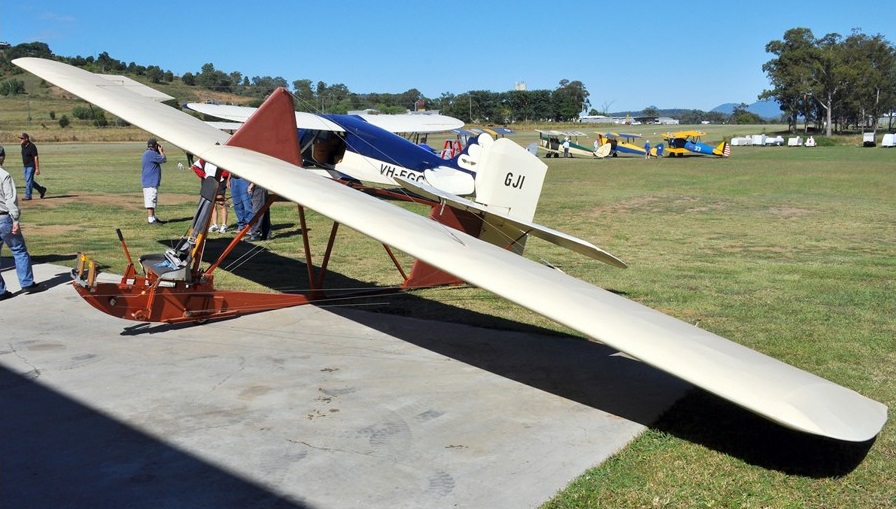
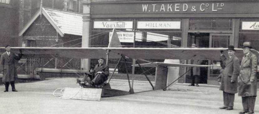
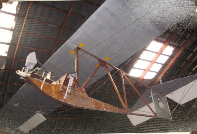
Designed by Roger S. Dickson and like other primary gliders of the 1930s, the Dickson Primary was aerodynamically unambitious, with its emphasis on low cost and simplicity. It was a wooden high wing aircraft, carrying the pilot on an open seat with a largely open, flat truss girder fuselage behind.

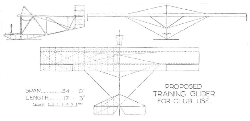
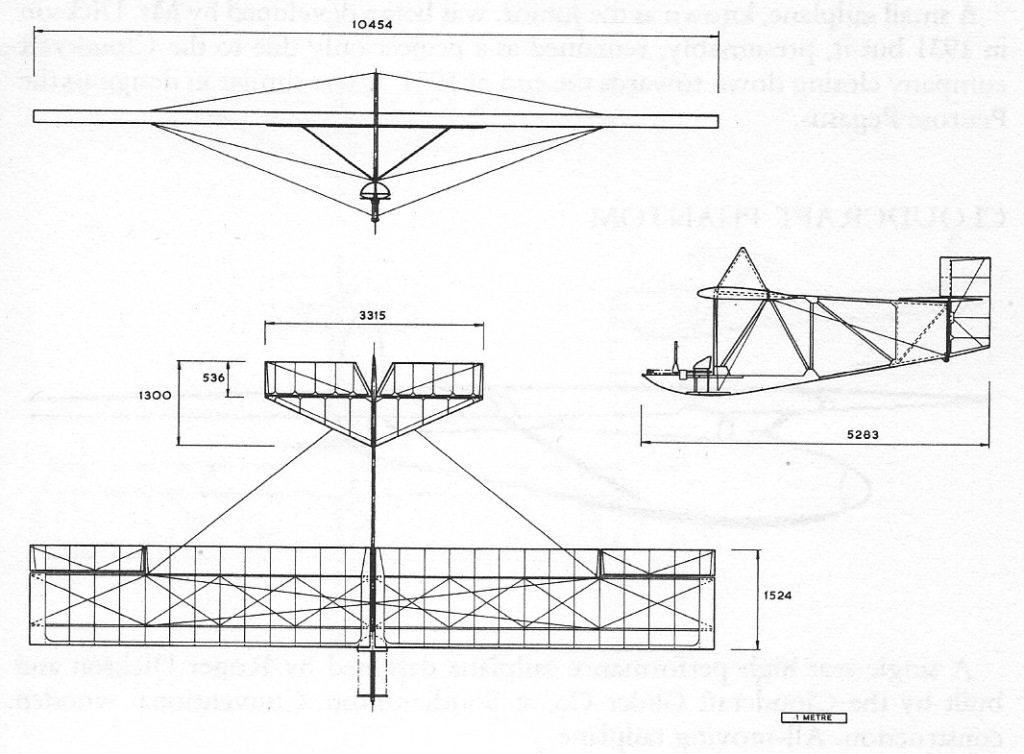
The wing had a two-spar fabric covered structure and was completely rectangular in plan. Ailerons occupied approximately ⅓ of the outer trailing edge. The wing was mounted on the horizontal upper beam of the three-bay fuselage Warren girder. The lower beam, angled slightly upwards rearwards, carried the pilot’s seat and controls at its forward end. Pairs of landing wires ran from a longitudinally-orientated inverted V-shaped pylon above the centre of the upper wing to the two spars near the inboard edge of the aileron. Similarly arranged flying wires ran from the same wing points to the keel. Bracing wires from the rear spar, at the same point as the flying wires, were anchored to the lower rear corner of the flat fuselage girder to limit sideways flexing.

The seat and exposed control column were located just ahead of the wing leading edge. A simple skid acted as undercarriage. At the rear, a fabric-covered tailplane, with swept leading edges and carrying rectangular elevators, was mounted on the upper fuselage beam over the whole of the aft fuselage bay. The rearmost vertical member of the girder carried a near-rectangular rudder, which projected above the fuselage led by a slender fin. Lateral stability was enhanced by the fabric covering of the rear bay of the fuselage.

The Dickson Primary flew for the first time in 1930. The designer of this glider has carried out extensive flight trials, and the machine behaved beautifully in every way, proving exceptionally stable. The only slight adjustment made was to fit the wires inside the rudder pedals instead of outside, to slightly reduce the gearing.

Only nine Dickson Primarys have established individual identities. However, a Cloudcraft Glider Co., Southampton, advertisement from July 1931 claimed that there were “over one hundred in use at the present time” in the UK, United States, Australia, New Zealand and South Africa. Some of these may have been built from kits, others from plans published in books and in or by magazines like Flight or bought from Cloudcraft. Certainly one example was built and flying in New Zealand by March 1931. UK gliding clubs (GC) flying Dickson Primarys included the London GC, operating at Dunstable, the Southampton GC and the Stockport GC. The last built their Dickson from plans. Seven years after the first flight, full working drawings were still on offer for 30/- (£1.50) from Flight itself, as they had been in 1931.

Dickson Primary Construction

Gallery

Dickson Primary
Wingspan: 34 ft 3 in (10.45 m)
Wing area: 170.0 sq ft (15.79 sq.m)
Airfoil: Clark YH
Aspect ratio: 7.0
Length: 17 ft 4 in (5.28 m)
Empty weight: 180 lb (82 kg)
Crew: 1