The 1913 single place, open cockpit biplane was motion picture and stunt pilot Al Wilson’s first effort as a teenager, a Curtiss pusher type that only gained 50′ altitude and refused to turn. It was abandoned because of structural fatigue after a few hard landings.
Aircraft
Wilson, Al & Herbert
Ocean Park CA.
USA
Airplane builder circa 1913-17.
Wilmington Aero Club / WAC Delaplane
Built in 1910, the Delaplane was designed by Robie Seidelinger as a single place open cockpit biplane. Powered by a 45hp Elbridge engine, the elevator was in the front, rudder in the back, and ailerons were under the lower wings.
The machine made a couple of short flights in 1910, rising from the ground a few feet, according to Delaware Aviation History. It was later destroyed in a hangar fire.
Wilmington Aero Club / WAC
Wilmington
DE
USA
Circa 1910 built the Delaplane
Wills 1910 monoplane
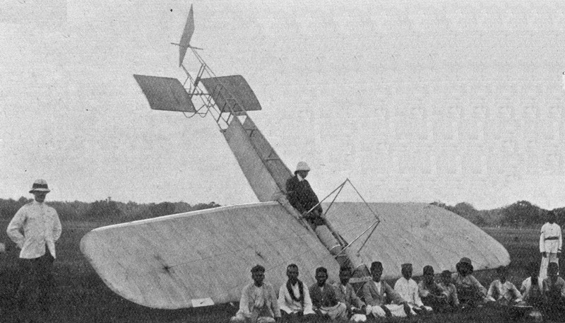
Wilfred Wills, motor engineer of Messrs Addison and Co., Madras, India, built a Blériot-inspired monoplane, powered by a 20 hp Ford engine, in four weeks. It was tried out on 2 November 1910 on the Island at Madras.
Although there was a strong wind blowing Wills succeeded in making three very short flights. During the last one the machine was somewhat damaged, but the repairs were put in hand at once and two days later a further trial was made with the result that a flight of 30 yards at the rate of 35 to 49 miles an hour.
Willoughby Delta 8 / Delta F / Delta 9
From about 1937, the London-based Willoughby Delta Company was considering the construction of a flying wing airliner. Early in 1939, the Delta 9 was to be a tri-motor monoplane with a span of over 100 ft (30 m) with a thick and wide chord centre section, outboard of which the wing was thicker and much greater in chord, in part forming one of a pair of tail booms that carried the double finned empennage. Its trailing edge was at about 20° to the centre line, continuing forwards then turning through 70° to produce the trailing dge of the outer wing section. This was narrower in chord than the centre section. The Delta 9 was seen as a realistic approximation to a true flying wing, with its advantage of a well-distributed load because of the absence of parts like a fuselage which did not contribute to lift. There was also the intention of producing an aircraft that was essentially stall-free.
The unusual design called for a lot of preparatory wind tunnel work, carried out in the UK at the National Physical Laboratory, the City & Guilds, Farnborough and Queen Mary College, London. Valuable pressure distribution measurements were made in the United States at the Guggenheim Institute of New York University. The results were encouraging, producing for example curves of lift coefficient versus angle of incidence that increased linearly in the normal way and then flattened without the usual decrease in lift associated with the stall. It appeared that, at high speed and low angles the forward part of the wing provided most of the lift, but as the stall approached the rear part contributed more. These results encouraged the company to build the Willoughby Delta 8 to investigate the general aerodynamics of the layout with a smaller aeroplane. The exact name seems to be uncertain: the contemporary (February 1939) Flight article calls it Delta 8, in line with the airliner named as Delta 9, but the registration documents from that January refer to the Delta F and the latter name has been widely used. The design had first been announced in Flight in 1937 as the Delta F. The Delta 8 was not a scale model of the proposed airliner, but the arrangement of its lifting surfaces was similar.
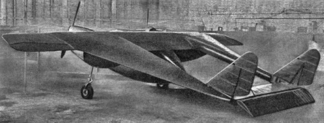
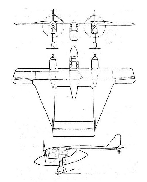
A twin-engined aircraft constructed of wood, the Delta 8 was a twin boom machine. It had a central nacelle, almost elliptical in profile, suspended beneath the wing and containing the glazed cabin. This had tandem seats, accessed via a starboard side door. The wings were built around two conventional transverse spars, unusual only in becoming deeper between the outer boundary of the centre section and the inboard limit of the narrow chord outer sections. The latter carried ailerons over the whole of its trailing edges. The longitudinal spars of the “side wings”, acting as booms, slipped into slots cut into the transverse wing spars. On each side, three longitudinal and very long chord ribs, plus a stiffening diagonal rib that ran to the rear end of the side wing, formed the aerofoil section of these wings. The transverse section of the side wings was also aerofoil shaped, blunt on the inner edge and fine outboard.
Two 125 hp (93 kW) Menasco Pirate C.4 four-cylinder air-cooled inline engines driving two-bladed propellers were mounted against the underside of the wing in steel cradles, at the points where the wing thickness increased. There was a wooden fairing behind, through which ran, to the front spar, the cantilever fixed main undercarriage legs, faired and spatted. The tailplane joined the rearmost inner edges of the side wings, carrying the tailwheel at its centre, and a broad elevator hinged clear of the rest of the structure. Small fins mounted over the tailplane carried balanced rudders, their overall profile almost triangular. The fins were externally braced to the tailplane.
The Delta 9 as described in Flight was expected to carry 36 passengers in two side wing cabins for a gross weight of 38,000 lb on three 1,000 hp engines. The cabins were expected to be have at least a 6 foot headroom but lacked side windows.
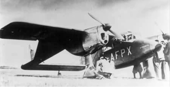
The design was constructed at Minster Lovell between Witney and Burford, and first flew on 11 March 1939 at Witney, registered as G-AFPX and named “St Francis”. On 14 May 1939, piloted by A.N. Kingwill, it was demonstrated at the Royal Aeronautical Society’s garden party fly-in at Great West Aerodrome, also at Heston Aerodrome. On 10 July 1939, it crashed near Bicester, killing the pilot Hugh Olley and the Delta’s designer, Percival Willoughby. The crash was not attributed to the novel configuration but to an ill-designed elevator trim tab that sent the Delta into a dive. With the death of the designer and the coming of war, no more was heard of this type of flying wing.
Delta 8
Engines: 2 × Menasco Pirate C.4, 125 hp (93 kW)
Wingspan: 34 ft 6 in (10.52 m)
Length: 26 ft 1 in (7.95 m)
Empty weight: 1,585 lb (719 kg)
Gross weight: 2,350 lb (1,066 kg)
Maximum speed: 183 mph (295 km/h; 159 kn)
Cruise speed: 165 mph (143 kn; 266 km/h)
Stall speed: 60 mph (52 kn; 97 km/h)
Range: 340 mi (295 nmi; 547 km)
Crew: 2
Willoughby Delta Company
The Willoughby Delta Co. Ltd had registered offices in Moorgate, London, UK.
Operated circa 1937
Willoughby War-Hawk
The Capt Hugh L. Willoughby War-Hawk built circa 1910 was described in Aero 10/14/11: “[Willoughby}, who built the famous War-Hawk, perhaps the largest biplane ever constructed…”
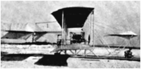
Hugh L. Willoughby (1856-1939) made his first flights in this machine at Atlantic City in the autumn of 1910. The pusher biplane with dart-shaped tail surfaces featured design cues from both Wright and Farman. It was powered by a 30 hp engine built by the Pennsylvania Automobile Co.
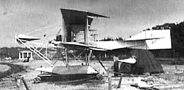
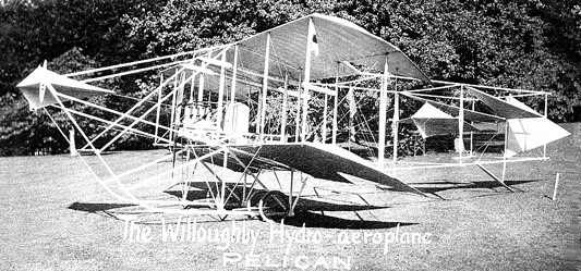
Willoughby Pelican
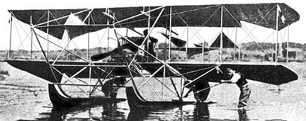
The 1911 Pelican was a single place “modernized” Wright-type hydroaeroplane by Capt Hugh L. Willoughby with a 50hp tractor engine; span: 30’0″. Patented double tails, brass-sheathed twin pontoons, a side-mounted wheel for pitch control, a control column that worked the rudders for yaw, shoulder-operated ailerons, and a spring-mounted pedal accelerator as in an automobile but working in reverse—depress to close the throttle, and foot off for full speed.
Willoughby, Capt Hugh L.
Newport RI.
USA
Aircraft builder circa 1910-11.
