Self-taught 31-year-old amateur builder Chris Christiansen designed and flew his third homebuilt airplane, the high-wing Savor, in just 15 months. The Savor, which is intended as a cross-country flying machine.
The Savor has a wingspan of 23.5 feet, and has aluminum control services and a fiberglass empennage and wings similar to a GlaStar.
The landing gear is aluminum rod. The cage frame goes all the way back to the tail. The most challenging aspect of the construction was the molds for the skins. The frame had the shape. The shells are one piece. Because of the angles and curves, the shells didn’t want to come out of the molds.
The shells are held in place by metal fasteners. The wings are removable. The wings are designed to have fuel tanks, 10 gallons on each side, and an additional fuel tank in the rear passenger compartment.
The front seat is 36 inches wide, while the backseat measures about 27 inches. The frame can accommodate someone who is 6 feet tall. The seat is 12 inches off the floor.
The interior is finished with textured semi-plastic foam. The texture can hide a lot of flaws and it is good for soundproofing. That’s 2 inches of insulation. The airplane also has carpet to help take the sound down.
Empty weight is 1,110 pounds, while gross weight is 1,550 pounds for the airplane, which cruises at 165 mph and lands at 60.
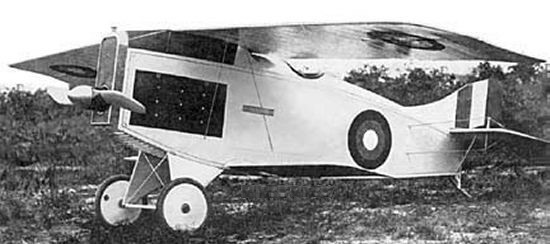
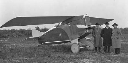
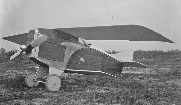
Co-designed with aviation pioneer, Vincent Burnelli (who only admitted to designing the fuselage), the Christmas Bullet was intended to meet a requirement for a military scout plane. The single-engine biplane was fitted with unbraced cantilevered wings designed to flex during flight. This gross lack of wing strength led to in-flight structural failures of both aircraft on 30 December 1918 and 1 May 1919.
This failure aside, the Bullet was noteworthy for being the first or one of the first aircraft to introduce a veneer-clad fuselage to reduce skin-friction drag and interconnected movable ailerons on the wing trailing edge. Christmas received a patent for the Bullet design in 1914, a fact which he used to make the claim that he had invented the aileron. Dr. Christmas even claimed that the US government bought the rights to his movable ailerons in 1923 for $100,000 to avoid a copyright infringement suit, but there appears to be no evidence to support this claim. In fact, Christmas is only one of many early pioneers who claim to have invented the aileron, including the Wrights and Glenn Curtis.
Christmas seemed to have persuaded his backers to finance him based on two previous aircraft, for which no evidence ever existed.
Christmas managed to find funding to build two ‘proof of concept’ aircraft to demonstrate his ‘ideas’ of a deliberately flexible wing inspired by those of birds, and tepid support from the US Army, which loaned an engine for ground-testing and the services of a test-pilot, Cuthbert Mills. A flight was attempted in the first aircraft, whereupon the wings peeled off during take-off, and the aircraft crashed, killing Mills. Christmas claimed that the aircraft had reached a speed of 197mph.
A second aircraft was built, and a propeller issued by the Army, despite the loaned engine having been destroyed during the unauthorised flight as Christmas had kept this secret. The second aircraft also crashed, also fatally. Christmas was still trying to sue people for claiming the aircraft had killed its pilots as late as 1930 and insisted the aircraft had reached a speed of 222mph.
At Exeter Airport, during 1948-1950, a series of four-seat lightplanes were constructed: Series 1 CH.3 Ace, Series 2 CH.3 Super Ace, and Series 4 CH.3 Skyjeep. The first of these high-wing cabin monoplanes was flown in August 1946, but high operating costs and unacceptable control system affected sales of the Ace and Super Ace.
The prototype CH.3 Series 1, was fitted with a 125 hp Lycoming engine, a single fin and rudder, and a wooden wing.
Production versions, the CH.3 Series II, was all-metal and fitted with a 145 hp DH Gipsy Major 10 engine. It also has the twin fin and rudder assembly later fitted to the prototype.
The CH.3 Series III had a tailwheel landing gear.
The Series IV version of the Series III had a hinged rear fuselage deck.
By August 1959 the tail wheel undercarriage CH.3 Srs. 4 Skyjeep VH-RCD four-seater had a deepened rear fuselage.
Engine: 1 x Gypsy Major Mk.10, 145 hp Wingspan: 36 ft Length: 21 ft 6 in Empty weight: 1344 lb Loaded weight: 2350 lb Max speed: 126 mph Cruise: 110 mph Stall: 38 mph Range: 400 mi Seats: 4
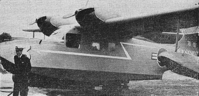
Constructed at the Republic of Korea Chinhae Naval Shipyard in 1957, the then un-named flying boat was of mixed metal and wood construction. Power was two 213 hp Continental 0-470-11 engines.
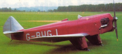
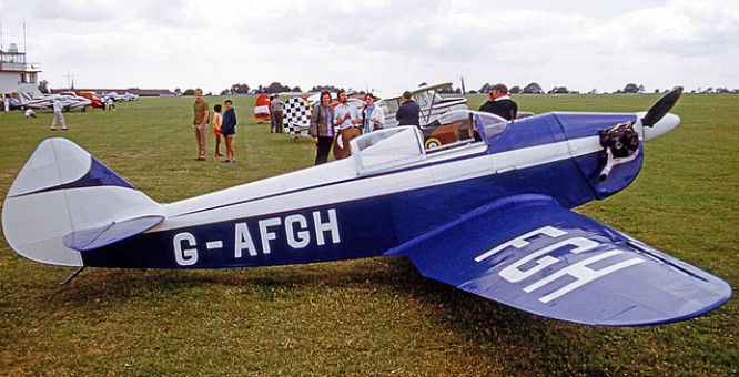
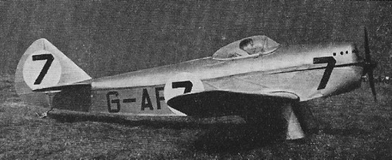
A single-seat light aircraft designed by Hon Andrew W. H. Dalrymple and A. R. Ward. A low wing open-cockpit wooden monoplane with fixed “trousered” landing gear and Carden-Ford engine, first flown April 1937.
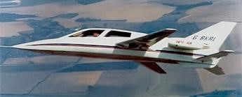
Ian Chichester-Miles, formerly Chief Research engineer of British Aerospace Aircraft Division at Hatfield, Hertfordshire, established Chichester-Miles Consultants (CMC) to develop a high performance light business jet.
Design of the four-seat Leopard started in January 1981 and was sufficiently advanced for a mockup to be completed in early 1982. Detail design and construction of a prototype by Designability Ltd of Dilton Marsh, Wiltshire, began in July 1982, under contract to CMC.
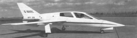
CMC Leopard cn 001
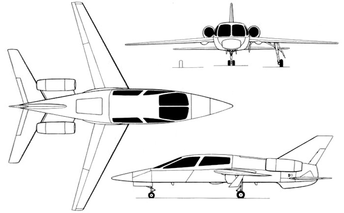
A four-seat light business jet aircraft, the wings are two-spar structure, primarily of GFRP, with some carbonfibre reinforcement. Full span electrically actuated trailing-edge flaps of carbonfibre, with deflections of +/- 45° for high drag landing and air-braking/lift dumping. No ailerons or spoilers. Thickness/chord ratio 14% at root, 11% at tip. Sweepback at quarter-chord 25°.
The Leopard airframe has an all-moving fin and tailplane and wings that combine laminar flow with supercritical technology.
Cantiler mid-wing monoplane. ARA designed wing section and 3D profiles combining laminar flow and super critical wing technology.
The fuselage is built in three sections: Unpressurised nose section accomodating avionics and nosewheel gear when retract, pressurised cabin section (production aircraft only) and unpressurised rear section providing a baggage bay, with fuel tanks below and equipment bays to rear.
Basic monocoque structure, primarily of GFRP with some carbonfibre reinforcement; fore and aft cabin bulkheads, engine and tailplane axle frames moulded in.
Pressure cabin section divided approximately along aircraft horizontal datum, with upper section formed by electrically actuated upward opening canopy hinged at windscreen leading-edge. Multiple latches around canopy lower-edge. Bonded-in acrylic side windows carry pressurisation tension. Nose opens for access to avionics.
Powered by two NPT 301 engines developing 300-350 lb thrust, this glass-fibre composite mini business jet is designed to keep pace with Learjets and Jumbos. Complete with a glass cockpit, the Leopard will carry four passengers and baggage over 1500 nm at around 500 mph at 41,000-45,000 feet.
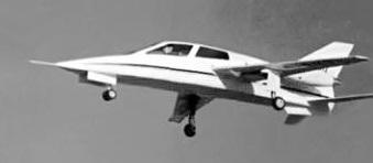
CMC Leopard cn 001
First shown statically at Farnborough in 1986, the first flight of the prototype (G-BKRL) took place on 12 December I988 at RAE Bedford, piloted by Cranfield test pilot Angus McVitie for a 27min flight.
CMC has limited the aircraft to 130kt and a maximum altitude of 3,500ft. The Leopard prototype was tested from speeds as low as 75kt with maximum 41° flap. Minimum zero-flap speed was less than 90kt. Undercarriage cycling was proved during this flight.
The prototype flying in the 1990 Farnborough display.
The converted missile NPT301 turbojet engines were intended solely for the 001, and NPT was slated to develop new engines for the final version of the aircraft. But when NPT went bankrupt, the entire Leopard project was delayed for one year until CMC teamed up with Williams International Corp., Walled Lake, Michigan.
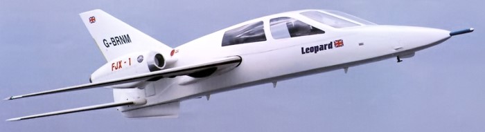
FJX-1 powered Leopard
Williams developed the FJX-1 engine for CMC’s first production-configured aircraft, the 002, built at the Designability R&D Center in Dilton Marsh, England. Rated at 680 lb-thrust, the FJX-1 had more than twice the power of the NPT301. That was okay for the 002, but it was not quite enough for the final aircraft.
Engines: 2 x Noel Penny NPT 301 turbofan, 300-350 lb. Seats: 4. Cruise: 800+ kph. Range: 2775+ km.
As early as 1933, while still working at OSGA, Chetverikov had begun the development of a hydrofoil designed to patrol the Arctic areas. As there was no defined technical task, Chetverikov set the goal of obtaining a speed of 300 km / h and a range of 3000 km. Around 1936 the GlavsievMorPuti became interested in this development and decided to contract Chetverikov for its construction. This event marked the emergence of the ARK-3. The objective of the model was Arctic exploration and patrol, liaison with ships, and the transfer of personnel and assets north.
Chetverikov received the necessary funds for development, the allocation of his own production base in Sevastopol and a major change of subordination, moving from the civil structure of the GVF to work under the direction of the State Directorate for the Aeronautical Industry (GUAP).
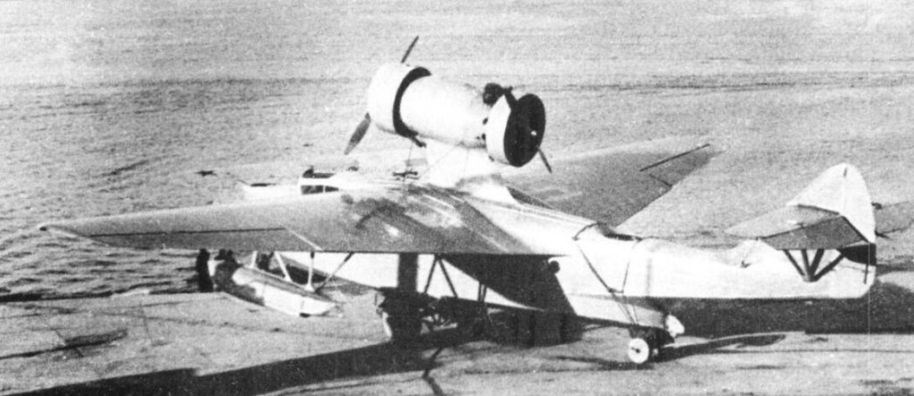
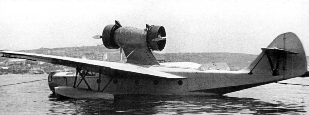
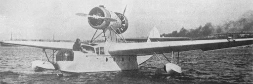
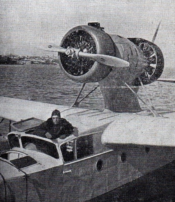
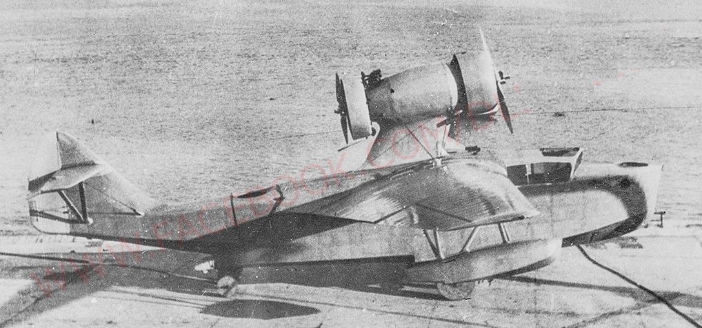
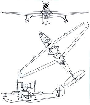
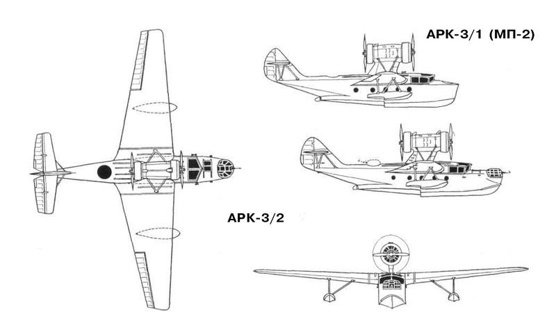
The Chyetverikov ARK-3 (ARKtichyeskii – arctic) was a multi-role flying boat designed for Arctic operations. It featured a conventional flying boat hull, with high cantilever wings equipped with floats at mid-span. The two piston engines were mounted in tractor-pusher fashion on a pylon above the fuselage.
The ARK-3 was designed as a cantilever high-wing hydrofoil with two Shvetsov M-25 635 hp engines installed in tandem on a pylon located in the center, braced by struts, which were later replaced by rigid uprights. The two engines powered variable pitch VISh (Hamilton Standard) propellers.
The ARK-3 was of mixed construction, with a 14-metre (45.9 ft) long Duralumin stressed skin fuselage; wooden wings of MOS-27 aerofoil section and set at 5° angle; duralumin tubing tail surfaces; and ailerons with fabric covering. The dual control enclosed cockpit housed two pilots sided by side with two gunners/observers in bow and dorsal positions where a 7.62 mm machine gun could be installed. In the first prototype built these areas were simply left open. The second prototype built installed turrets in both positions. Strut-supported wooden floats, at approximately half-span; and a pylon-supported engine nacelle housing tandem radial engines with Townend ring cowlings; completed the structural elements, built with a safety factor of 5.5.
At the beginning of 1936, the construction of the first АРК-3 prototype was finished in Sevastopol Factory No.45, which was tested in the summer of that year, showing quite acceptable results. The tests culminated in September, achieving a speed at sea level of 252 km / h and 2600 meters reached 308 km / h. The flight ceiling was above 7600 meters. Shortcomings were also highlighted: poor design of the bow splash deflectors, weakness in the powertrain. Even a small 0.25 meter wave ran across the entire bow in front of the cockpit and the splashes reached the propellers.
This was considered to be due to the short length of the bow and its narrow width of only 1.7 meters. There were hardly any problems for take-off, but during the landing on the water there were commonly waves that swept over the bow.
Performance was deemed to be good, prompting an order for a second prototype with the fuselage lengthened by 60 centimetres (24 in) to 14.6 metres (47.9 ft) and a slightly enlarged wing chord; this was designated ARK-3-2 and the first prototype was re-designated ARK-3-1 or MP-2 (Mosrkoi Passazhirski or Naval Passenger Transport). The second prototype ARK-3 featured more powerful engines, longer hull, and manual guns fitted in a manual gun turret in the bows and a dorsal sliding hatch. The APK-3/2, already equipped with weapons, was released in May 1938 with two M-25A engines. The weight of this model increased by 400 kg. A production order for five aircraft was placed, with production commencing immediately.
This first model was modified in order to eliminate the defects indicated. Splashes were considerably reduced with the installation of deflector blades forward. The fastening straps of the driving nacelle were replaced by rigid supports.
25 April 1937 Russian pilot A.V. Erchov
On 25 April 1937 Russian pilot A.V. Erchov reached a height of 9160 meters with a payload of 1000 kg in the Crimea with a Chetnerikov A.R.K. 3 twin-engine flying boat, so he surpassed the existing world record, which was still held by the Frenchman Bourdin, who took off in 1933 with a load of 1000 kg 8864 m high.
On 14 July 1937 the ARK-3-1 was destroyed following a structural failure when after a sudden landing the engine fell forward causing the death of the pilot; the ARK-3-2 lost its tail in flight and was destroyed exactly one year later.
At that time, five other copies were found in a different state of completion in addition to the prototypes, and the programme was cancelled.
The ARK-3 formed the basis for the MDR-6 (Che-2) hydrocanoa.
ARK-3-1 / MP-2 The first prototype ARK-3 renamed after the second prototype was ordered Engines: 2 x M-25, 710 hp takeoff / 630 nominal hp Wingspan: 20.00 m Length: 14.60 m Wing area: 59.5 m² Wing profile: MOS-27 Empty weight: 3,242 kg Normal takeoff weight: 4787 kg Overloaded weight: 5800 kg Oil weight: 150 kg Fuel weight: 870 kg Total load capacity: 1545 kg Wing loading: 83 kg / m² Power load: 3.4kg / hp Maximum speed at sea level: 252 km / h Maximum speed at 2,600 meters: 308 km / h Landing speed: 105 km / h Practical ceiling: 7600 m Range: 3000 km Endurance: 7 hours Ascent time to: 1000 m – 3.5 min 2000 m – 7.0 min 3000 m – 10.0 min 4000 m – 14.0 min 5000 m – 18 min Accommodation: 3
ARK-3-2 The second prototype ARK-3. Engine: 2 × Shvetsov M-25A, 544.36 kW (730 hp) takeoff / 650 hp nominal Wingspan: 20 m (65 ft 7-1/4 in) Wing area: 59.5 m2 (640 ft2) Length: 14.6 m (47 ft 11 in) Empty weight: 3,642 kg (8,029 lb) Normal takeoff weight: 4787 kg Overloaded weight: 5800 kg Fuel weight: 820 kg Oil weight: 160 kg Total load capacity: 1958 kg Wing loading: 94 kg / m² Power load: 3.8kg / hp Maximum speed at sea level: 260 km / h Maximum speed at 2600 m: 320 km/h (199 mph) Landing speed: 110 km / h Endurance: 7 hours Range: 3000 km Ascent time to: 1000 m – 3.5 min 2000 m – 7.0 min Service ceiling: 8,500 m (27,890 ft) Rate of climb: 4.76 m/s (937.4 ft/min) Crew: 4 Capacity: 10 pax Armament: 2 x 7.62 mm machine gun Bombload: 1,100 kg
ARK-3 MP2 Designation of the five production aircraft and the initial designation of the first prototype.
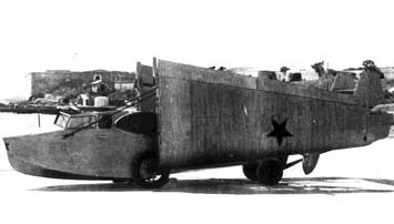
The development of an aircraft to carry out operations from submarines was taken over by IV Chetverikov in 1931. In its design, Chetverikov decided to start from the already proven design used in the OSGA-101 light flying boat. The new model was known as SPL (Russian: Четвериков СПЛ), after the acronym for Samoliet Podvodnoy Lodki or Airplane for submarines.
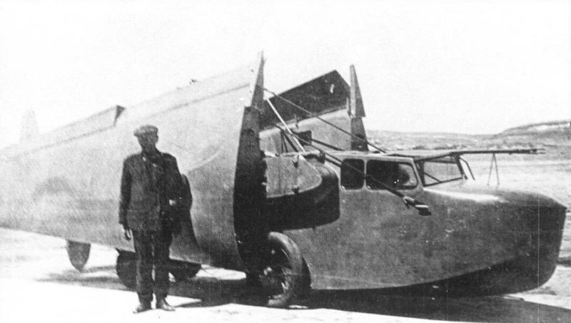
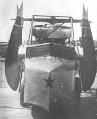
As fundamental differences, the general dimensions were reduced in order to allow the aircraft to be accommodated in a sealed hangar of only 2.5 x 7.5 meters. Systems were also developed that would allow the wing, the power plant and the stabilizer consoles to be transformed, using quick-action fixing screws instead.
The decision to build a flying boat of minimum dimensions also had its cost. The tail had very little area, so the flying boat had little stability. The visibility of the cabin was poor, especially for the observer, since the crew was forced to position themselves towards the center of gravity of the aircraft in order to reduce the length. To reduce the weight, the flying boat did not have the possibility of carrying any type of armament. The resulting aircraft looked more like a sports competition model than a military aircraft.
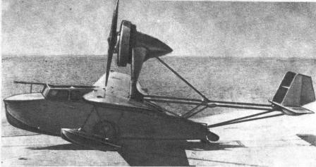
The SPL was designed as a high-wing monoplane flying boat. The wing, similar to that used on the OSGA-101, featured a three-spar configuration with a trunk frame and wooden construction. The areas on the outside of the wings between the leading edge and the intermediate spar were covered with plywood. The rest of the wing presented fabric covering, sewn with thread to the ribs.
Unlike the OSGA-101, on the SPL there were no fasteners on the first and third stringers. In this way the force of the support was exerted only on the central beam. In the extended position, the wing was secured by a quick-release fastener located at the top of the center spar. At the bottom was a gimbal that was inserted into a cavity in the centroplane. To pick up the wing, it was enough to release the fixator, rotate the wing console around the axis of the spar and move them towards the sides of the hull.
The SPL wing was designed using the MOS-27 airfoil with a relative thickness of 18% at the root section and 12% at the tips. This fact, together with a considerable narrowing of the wing, made it possible to obtain a break in the flow at the wing tips when operating with large angles of incidence. For this reason, it was enough for the pilot to pull the stick a little hard on landing so that the plane began to dive on the wing. At that time, the phenomenon of wingtip vortices was little studied, so the fault for this behavior was attributed to the poor transverse stability of the model. Attempts were made to cure this problem by increasing the wing’s wing gradient to about 5°, but the effect was nil. According to Chetverikov himself the problem could be compensated thanks to the great effectiveness of the ailerons.
The large-area wings occupied the entire trailing edge of the consoles and featured two sections: an inner or root section and an outer section. The inner sections could be used as flaps during landing. The wings were made of wood and featured fabric-covered box-type spars. The leading edge was covered with plywood.
The underwing floats had a wooden structure with frames and braces, covered with plywood. In the SPL, unlike the OSGA-101, the construction of these floats was simplified.
The hull of the SPL was similar to that of the OSGA-101 and featured all-wood construction. The structure had several frames with stringers and braces and plywood sheathing. The hull design demonstrated excellent hydrodynamic qualities, which was necessary for the operation of the model in the open sea. The large angle of the keel reduced the overloads when riding the waves and the high rails ensured a smooth takeoff and landing in tidal conditions.
The three-sided tail beam was made of steel tubes and its rigidity was ensured by means of cable-stayed straps. The control cables for the rudders were routed inside the tubes of the structure. The empennage was built on a fabric-covered welded steel tube structure. The keel spars and stabilizers as well as the ribs and leading edges were constructed from thin steel tubing. Unlike the OSGA-101, in the SPL the stabilizers had a biplane structure in order to reduce their wingspan.
The SPL lacked its own landing gear and for operations on land, removable wheels were used whose axles were fixed to a tube that passed through the hull from side to side.
The power plant selected was the excellent 100 hp M-11 driving a two-bladed, fixed-pitch wooden propeller. This propeller had a diameter of 2.3 meters. Originally, an annular Townend-type hood made of aluminum was installed, but it was soon found that the aerodynamic improvements of its use on the M-11 engine they were not considerable, reason why it was eliminated. The engine was located on a high pile conceived of welded steel tubes and designed to prevent water splashing on the propeller during takeoff and landing operations. To facilitate its packing inside the narrow container, the engine lay down backwards. To achieve this in the SPL the drive location was slightly rearward, the strut could pivot and the rear mount base was moved rearward by the main tail tube. The motor control was carried out by sheathed cables that were collected along with it.
The optimum position on takeoff and landing ensured a wing angle of incidence of 6º, but during flight the optimum angle was 2º. For this reason, in flight, the nose of the flying boat was inclined slightly downwards, while the engine was at that moment totally in line with the flow of navigation.
In the motor gondola there was a 10-liter tank for oil and another 20-liter tank for fuel. The main fuel tanks were located in the hull.
The dimensions of the SPL once folded were only 7.45×2.12×2.35 meters. Flight readiness was achieved in 4-5 minutes and after the mission the wings, tail and engine could be folded in 3-4 minutes.
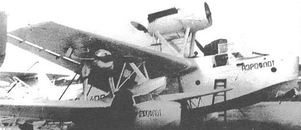
The SPL was fully painted silver. Originally it had no markings or symbols, but later on its nose and wings, above and below, the characteristic red stars were painted. The Gidro-1 example, which was shown at the Milan fair, featured Aeroflot symbols in blue on both gunwale and lacked the red stars.
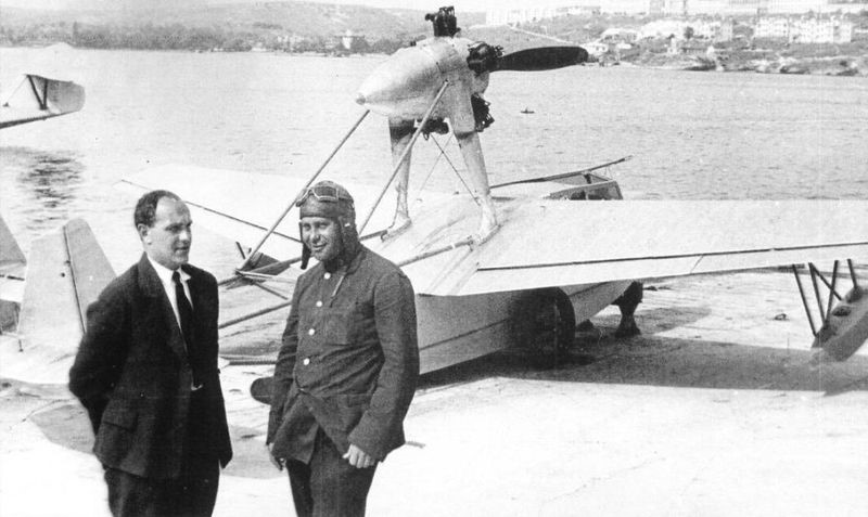
The SPL was built in the workshops of the Sled and Hovercraft Building Department (OSGA), subordinate to the NII GVF. The prototype was finished by December 1934 and moved to Sebastopol to carry out sea trials, which were completed on August 29, 1935. Its realization was in charge of the test pilot of Factory No.45 AV Krzhizhevski.
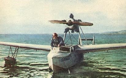
Designer Chetverikov and test pilot KrZhizhevski during SPL tests at Sevastopol Factory No.45.
The tests demonstrated the feasibility of the packing and unpacking operation of the aircraft in the submarine in a time of 4-5 minutes, its possible take-off and its effective recovery after the flight. The authors of the project managed to obtain a container only 7.45 meters long and with a diameter of 2.5 meters. In general, the SPL showed acceptable performance in the water, but its seaworthy conditions were not good, especially in the open sea. It was clear that very little more could be asked for an aircraft of this type, but in these conditions the aircraft was not very attractive to the military.
The Gidro-1 next to an MP-1bis with the colors of Aeroflot to participate in the fair in Milan in 1936.
In 1936 the SPL with the Aeroflot symbols and Gridro-1 denomination, participated in the Milan Fair, receiving a positive evaluation.
Gidro-1 tests on water.
On September 21, 1937, in this plane, the pilot AV KrZhizhevski established a world speed record of 100 km, reaching 170.2 km/h, and on October 7 of that year, he established a new distance record for aircraft of its category. when reaching 480 km and high when setting 5400 meters. Despite these results, the model did not have further development.
Documentary references to a flying boat built by Chetverikov have been found at Sevastopol Factory No.45. It could be a second issue of the SPL, but this is just conjecture.
SPL Power plant: М-11, 100 hp Wingspan: 9.6m Wing area: 13.4 m² Length: 7.4m Height: 2.72m Empty weight: 592kg Weight with normal load. 800kg Maximum takeoff weight: 879kg Fuel weight: 60kg Oil weight: 10kg Total load capacity: 208 kg Wing loading: 59.7 kg/m² Overloaded wing loading: 65.7 kg/m² Power load: 8kg/hp Overloaded power load: 8.8 kg/hp Maximum speed at sea level: 186 km/h Cruising speed: 174km/h Landing speed: 85km/h Endurance: 2 hours Range: 480km Practical ceiling: 5400 m Time to 1000m: 3.9min Time to 2000m: 8.7min Time to 3000m: 15.3min Time to 4000m: 25.5min Time to 5000m: 50.0min Accommodation: 2
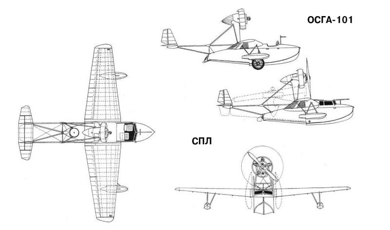
Chetverikov SPL and OSGA-101 three views, showing main differences