This airplane represents a further development of the CA-61 Mini Ace, which first flew in July 1965. The CA-65 is an all wood side by side two seater low-wing monoplane with retractable landing gear and dual controls, designed in 1964-65. It features a streamlined canopy, enclosed engine, tapered wing and fully retrac¬table gear. Its wood construction cuts requirements for tooling and special jigs to a minimum. The wing consists of a centre section and two outer panels set at 3o dihedral. The wing structure is made up of two spruce spars, built up girder type ribs and is completely plywood covered. The fuselage is of conventional wood construction and covered with plywood. A manually operated flap is fitted under the fusealage. The empennage consists of ply covered fixed surfaces and fabric covered control surfaces. On the folded wing version the outer panels fold upwards from the centre section. Mechanically, inward retracting, main undercarriage legs are fitted. Two 11 Imp gallon fuel tanks are installed in the fuselage. Engines from 108 to 150 hp.
The CA-61 can be built as either a single-seat or side-by-side low-wing monoplane. It is designed for amateur builders with little or no previous experience in building light airplanes. With a minimum of tools, the plane can be assembled in less than 1000 working hours. The structure is light with low wing loading, so in addition to the stan¬dard Continental powerplant, a VW conversion can be substituted. Another option is the availability of either fixed tricycle landing gear or retractable tailwheel type. Construction is all wood, and the wing is made in one piece with a main and auxiliary spar
Engine 65-hp Continental Wingspan 27 ft 6 in Length 18 ft 11 in Gross Wt. 950 lb Empty Wt. 606 lb Fuel capacity 17 USG Top 120 mph. Cruise 100 mph. Stall 42 mph. Climb rate 1200 fpm. Takeoff run 200 ft. Landing roll 300 ft. Range 425 miles.
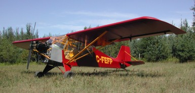
The LSA LITE STAR is the essentials and returns to the simplicity of stick and rudder. Low & slow in a gentle, agile airplane, makes flying fun again. This engine burns 5 USGPH and maintenance can be a DIY bonus. Parts & service on the engine & propeller are reasonable and inspections are minimal. A professionally welded, 4130 fuselage, and wings built with proven, extruded aluminum “I beam” spars, from a shop with 27 years experience building high performance aircraft. Gas tanks are in the wings, not the fuselage, for added safety. A high wing, tail dragger, side by side seating, fabric covered 4130 welded tube fuselage, fabric covered aluminum structure wings. Wheels, skis, or floats.
Gross weight: 1235-1350 Lbs. Empty weight: 650 Lbs. With Corvair or Continental O-200 HP rating: 80-100 HP (can also use Rotax, or Continental O200) Propeller: ground adjustable fixed pitch Gear: Tail wheel configuration / shock cord suspension
Cruise Speed: 100 MPH Stall speed: 35 MPH Rate of Climb: 600-700 Ft/min. Fuel capacity: up to 2×10 US gal. Endurance: 4 hrs 2009 PRICE LIST; 1) $22,000 US for Airframe kit, all structural components welded and painted. Includes, fuselage, tail, landing gear legs, control sticks, rudder pedals, engine mount, fire wall, doors, windshield & windows, wing kit with gas tanks. 2) $60,000 US for complete LITE STAR aircraft ready to fly. Basic instrument package includes air speed, altimeter, compass and slip ball , 12-volt system with master solenoid & battery. Basic engine instruments include RPM, CHT, oil temperature, oil pressure light. Any additional instruments or radio equipment is at extra charge.
Cruise: 100 mph Stall: 45 mph Range: 400 sm Rate of climb: 1000 fpm Takeoff dist: 200 ft Landing dist: 200 ft Engine: Corvair , 110 hp HP range: 65-110 hp Fuel capacity: 20 USG Empty weight: 650 lb Gross weight: 1320 lb Length: 21 ft Wing span: 30.5 ft Wing area: 160 sq.ft Seats: 2 Cockpit width: 39.75 in Landing gear: tailwheel
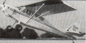
Designed by Morgan Williams Jr. Custom Flight Ltd., of Midland Ontario, has introduced a new kit aircraft called the Bright Star. In response to requests for a lower priced version of the North Star, the Bright Star was developed. It retains the high quality standards and size of the North Star, but with some of the “extras” left off. The Bright Star has a single, larger door, no flaps, spring steel gear, a square tail, and smaller gas tanks. The gross weight is 1800 pounds and it can use aircraft or auto engines from 100 to 180 hp. It will be licensed in the experimental/amateur built category. As of June, 2000, the prototype Bright Star has not flown yet. The North Star fuselage strength was retained in the Bright Star to allow use of a great range of engines, from 100 hp to 180 hp. Many of the wing reinforcements in the North Star were to accommodate the very powerful flaps. By eliminating the flaps from the Bright Star we were able to lighten the wing structure, lower the price, and produce a wing with the same strength as the Super Cub wing and the improved lift of the North Star. The North Star wing can be put on the Bright Star Fuselage for a little more money, this however defeats the concept of keeping the cost as low as possible. The larger North Star gas tanks can be used in the Bright Star wings. The Bright Star has a squared off tail, and a trim tab instead of the jack screw, the same as Champs and Citabrias. This tail works fine and is more economical to produce. There is only one door on the Bright Star and it is not split like the Cub door. It is one piece and similar in size to the Champ door making cockpit access easier. The door is hinged on the top so that it opens up against the wing and provides unobstructed access from in front of or aft of the wing struts. A leaf spring landing gear similar to that used on the Citabrias and Cessnas is substituted for the more complicated Cub style gear. Another way we reduced the purchase price was by eliminating the “bird cage” framework on top of the fuselage, and the belly framework under the fuselage. Instead tabs were welded on to allow the attachment of simple wood or aluminum framework made by the builder. Inexpensive wood stringers can also be supplied by the builder to keep the cost down or aluminum stringers can be purchased from CF Ltd.
Construction details WINGS: -Compression struts in line with aileron hinges, forces travel in a straight line instead of zig-zaging through the spars. -raked wing tip gives long trailing edge, maximizing aspect ratio and increasing effective wing span, does not block visibility.
leading edge metal (.020-2024 T3) extends about 4″ aft of front spar on top, giving a truer airfoil shape. -aileron moved outboard, requires less deflection for same response, less chance of inducing a stall at low speeds, much lighter stick forces, I would estimate double the roll response of a Citabria. -stainless steel drag wires included. -stainless steel drag wires extend through spars and use simple nut and block attachment system. -same airfoil as a Cub. -aluminum, preformed and drilled ribs. -predrilled, extruded aluminum spars. -hinges are prefabricated, ready to bolt in position. -leading and trailing edge aluminum is preformed. -stainless steel gas tank support straps. -wing mount hardware ready to bolt on. -more room between root and fuselage to work in. -gas tanks in wings TIG welded .040-5052 aluminum and hold a total of 23 U.S. gal/20 Imp. est. -gas tank shape is accurate and forms the airfoil shape in that area, plumbing installation and routing ensures good fuel flow in steep climbs and dives without needing header tanks. -aileron pulleys and cable concealed in wing. -cable does not come through top of wing.
FUSELAGE: -2 1/2″ wider in cockpit area. -one larger door, 35″ tall x 46″ wide hinges up to bottom of wing. -door handles on outside and inside of door. -baggage floor lowered to bottom longerons. -high ceiling in baggage area. -90 lb. baggage capacity. -deep “V” belly provides good drainage away from longerons and room to route cables under floor. -belly opening at tail end, can put a garden hose in the front and flush dust and dirt out of the aft end, tail post left exposed so will not trap corrosion causing dirt and moisture. -flat back on fuselage follows wing contour, creating lift. -toe brakes, with parking brakes. -instrument panel easily hinges down for access to instrument backs, is shock mounted, top edge is padded and dash edge fits under top panel flange so it cannot cut pilot in a crash. -boot cowl (around pilot’s feet) easily removable for access by removing 2 piano hinge pins. -dynafocal or straight engine mount. -no sheet metal screws – nut plates welded and riveted in mean no screws to come loose or holes in tubing to introduce moisture. -fuselage sandblasted with extremely fine sand, epoxy primed. -tail wheel spring front bolt in a welded bushing to keep water out. -all control stops adjustable, tail stops mate with discs not bellhorn edges to reduce wear. -fin offset for trim. -stainless steel tail brace wires. -extra cable fairleads so cables cannot chip paint on tubes. -one large handle on the right side of rear of fuselage. -strength increased in high load areas, closer trusswork in aft fuselage. -leaf spring landing gear is taller for long prop clearance, also gives increased angle of attack, producing lower takeoff and landing speeds, has wider wheel base, so greater stability. -steps on landing gear give access to top of wing and easier entry to cockpit. -front and rear seats fixed in place. -dual controls.
Bright Star Engine: Lycoming O-360, 180 hp Hp range: 100 to 180 hp. Fuel capacity: 23 U.S. gal./ 20 Imp. gal. Wing span: 36 ft 4 in Wing area: 190 sq. ft. Length: 23.5 ft Height: 7.5 ft Gross weight; 1800 lb Empty weight/: 1000 lb ROC: 1000 fpm Top speed; 140 mph Cruise; 100 mph Stall; 35 mph Take off distance; 225 ft Landing distance: 275 ft Seats: 2
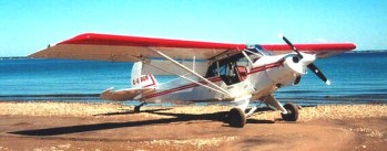
Designer Morgan Williams Jr. started with a Super Cub design to build a better aircraft. The design of the North Star had four parameters. It had to be stronger, more durable, fly better, and be easier to work on. There were weak spots in the Cub that were known but really show up when raising the gross weight. The SC is a J3 with a higher gross and a bigger engine. With an added extra set of diagonals to the fuselage, shortening the spans in a structurally sound way. The wings are similarly strengthened with the spar reinforcements copied and improved from the Pawnee crop duster. Many more durability and other enhancements are listed in the construction specs. The landing gear legs are 3″ taller to give higher angle of attack for better takeoff. The sheet metal on the top of the leading edge is extended to about 4″ aft of the front spar. This gives a truer airfoil shape without the concave fabric between ribs in this critical section of the wing. The back of the fuselage is not the typical “peaked roof” as seen on most Cubs. Piper flattened the back on the agricultural models to facilitate a hopper door. By chance, since the back more closely followed the wing shape, they found the “A” models had a slightly lower stall speed. The trailing edge of the wing is extended. This wing has 3 feet more effective span on each side. The longer trailing edge also puts the aileron outboard 2 feet. The aileron, like the flaps, also has greater cord and better airflow through the slot. All the North Stars are rigged flat, no washout. The flaps are larger, 2′ longer and 4″ wider cord than cub flaps. The superior hinge geometry, and the redesigned radiuses on the aft bottom portion of the wing ribs of the North Star, produce the improved, energised, air flow through the large slot that adheres to the top surface of the flap, making the slow speed performance exceptional. With no flaps the North Star lifts off at 35 mph. With 20 degrees of flap it jumps into the air on takeoff at 25 mph, and climbs! This low speed means less ground wasted accelerating. Full flaps, no power on approach gives 800 FPM descent. Just touch the throttle to 1200 RPM and the path flattens out giving excellent descent control. Sideslips also work and when performed with full flaps can give 1,000-1,500 FPM rate of descent. After you become familiar with the airplane a normal approach will be full flap, 40mph, no power, over the trees, sideslip, straighten, flair, flaps off, brakes on. The shocks are a hydraulic shock/coil spring combination. The long stroke and hydraulic shock damping give much superior protection from those extra rough landings. Along with the kit, supplied is instructions on videotape, and a dozen 24″ x 36″ blue prints with full size details of the wing are included. For the fuselage: full size patterns for the floor boards and interior panels are supplied with a video to show how to make and install the interior. A binder is provided with 2 separate parts lists: hardware order lists with recommended suppliers and hardware location lists that tell where each bolt, pulley, etc. goes in the airplane. The binder also contains CAD detail drawings, indexed for the various areas and systems of the plane. It is set up so that new drawings can be added as they are created.
Fuel tanks in wings are welded .040-5052 aluminum and hold a total of 52 U.S. gal/44 Imp. gal./197 L. -2 doors. -baggage door. -baggage floor lowered to bottom longerons. -baggage floor extends 52″ aft. -90 lb. baggage capacity. -stainless steel belly framework, corrosion proof even if moisture does collect in belly. -6″ travel in adjustable front seat with tilting back. -rear seat tilts and lifts out for more cargo. -fish pole/ski tube behind baggage (option).
North Star Engine: Lycoming 0320 (150 hp). HP range: 150-180. Wing span: 36 ft 4 in Height: 6.8 ft. Length: 22.5 ft. Wing area: 190.7 sq.ft. Empty weight: 1170-1250 lbs. Gross weight: 2000-2200 lbs. (2300 on floats) Fuel capacity: 52 U.S. gal./44 Imp. gal./197 L. Speed max: 140 mph. Stall speeds at 2200 lb: 40 mph, No Power, No Flaps. 35 mph, No Power, or Full Flaps. 35 mph, Full Power, No Flaps. 30 mph, Full Power, Flaps. 25 mph, Full Power, Full Flaps. Cruise 82-41 prop and 600-6 wheels: 98 mph. Cruise on 2000 floats: 85 mph. Lifts off: 45 mph in 500 ft Climb: 600 fpm through 4,000 ft. Baggage: 90 lbs. Take off roll 180 ft Lift off and land-on floats: 35-40 mph, 9 seconds Range: 600 sm. Service ceiling: 16,000 ft. Seats: 2. Landing gear: tail wheel. Cockpit width: 29 in
A side by side, two seat, single engined, high-wing monoplane with conventional three axis control. Wing shape; tapering chord; yaw control by fully flying tail, circa 1982.
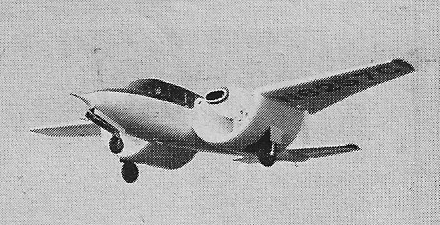
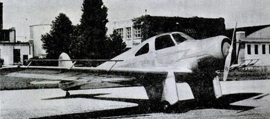
The Bauman Aircraft Corporation adapted a B-290 airframe for the Custer ‘channel-wing’ as the Custer CCW-5. First flown in July 1953 at Oxnard, California.
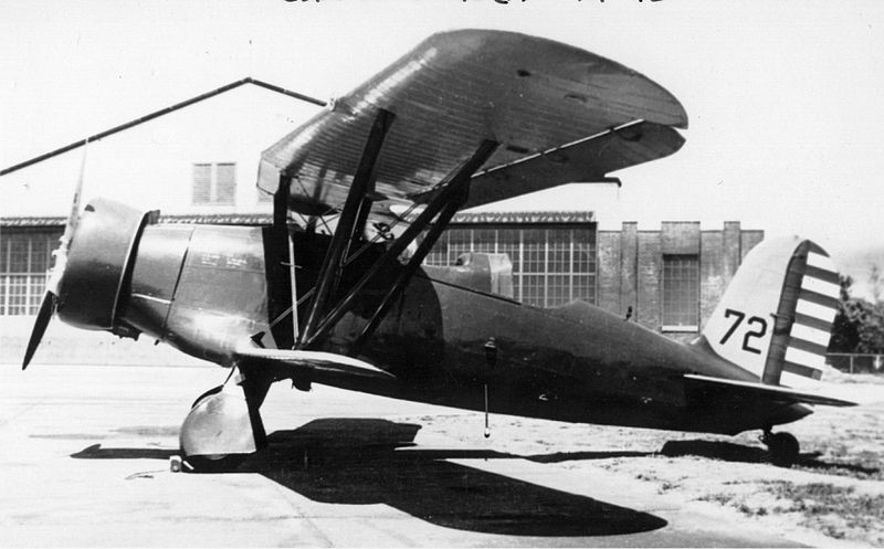
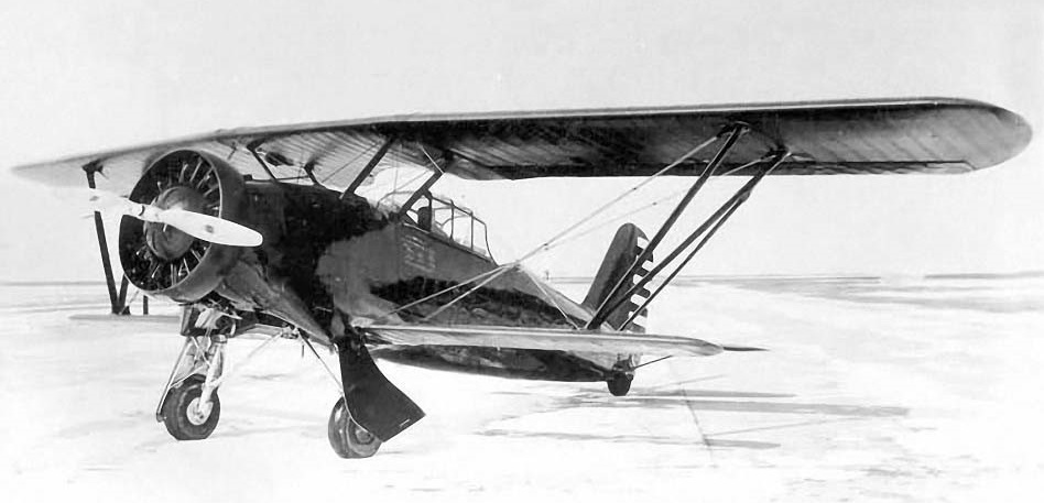
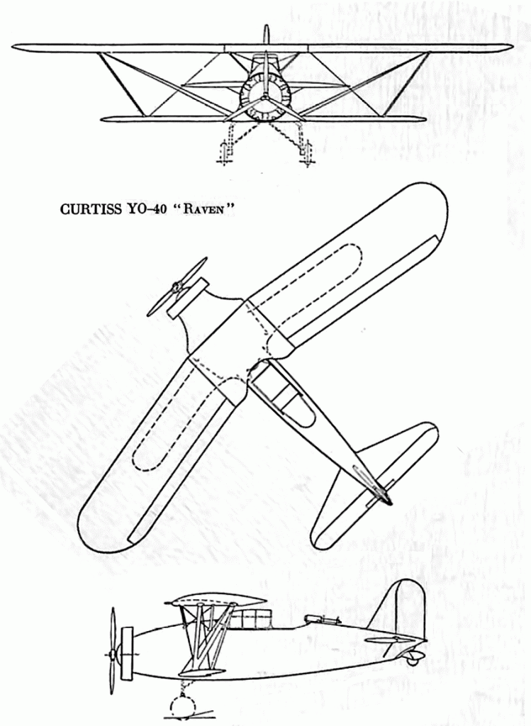
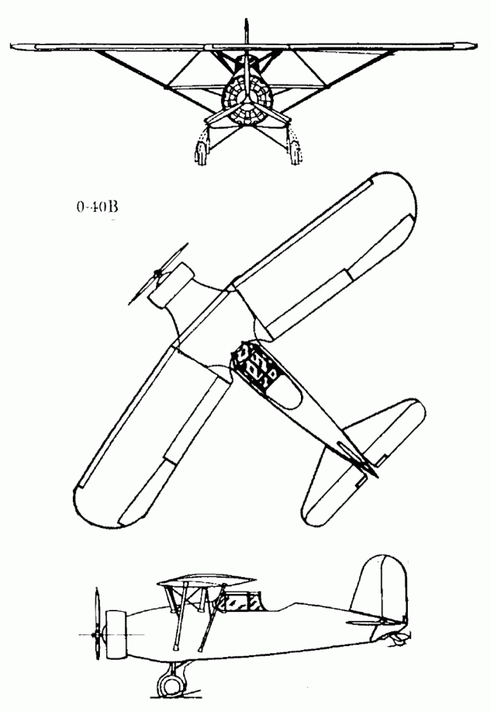
In 1931, in response to a United States Army Air Corps requirement for a new observation aircraft, Curtiss designed the Model 62, a single-engined biplane with the lower wing much smaller than the upper, known as a sesquiplane (i.e. “one-and-a-half wings”), while the outer panels of the upper wings were swept back to avoid centre-of-gravity problems. The lower wing was connected to the upper wing by one set of struts. It was of all-metal construction, with a monocoque fuselage and had a retractable tailwheel undercarriage with inwards retracting mainwheels, and was powered by a Wright Cyclone radial engine. The crew of two sat in tandem in open cockpits. It was armed with one fixed forward firing .30in machine gun in the right upper wing and one flexibly mounted .30in gun in the rear cockpit.
A prototype (sn 32-343), designated YO-40, flew in February 1932. It crashed on 20 May that year, and had to be returned to Curtiss where it was rebuilt with stronger wings and an enclosed cockpit as the YO-40A. The YO-40A was scrapped in 1938.
YO-40A
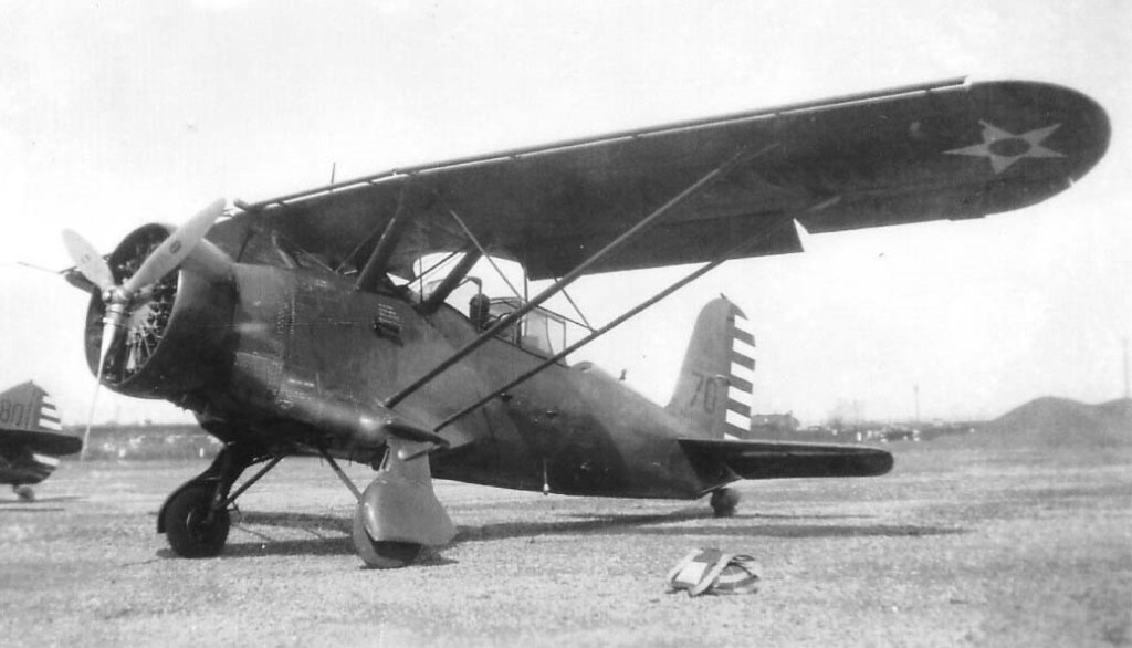
A further four YO-40As were ordered, but they were redesigned as monoplanes by removing the lower wing, the resultant aircraft being designated Y1O-40B. A stub of the lower wing had to be retained as it contained the retractable landing gear. The engine was upgraded to a more powerful R-1820-27 and the wingspan reduced by 2ft 4in. The new aircraft were heavier than the original prototype, and their performance was generally worse.
O-40B
The four Y1O-40Bs (sn from 32-415 to 32-418) were delivered in June 1933, and after service tests, were re-designated O-40B Raven, being operated by the 1st Observation Squadron of the USAAC. While the aircraft’s performance and manoeuvrability were good, the Air Corps was disappointed with the cockpit arrangements and the low fuel capacity, and no more orders followed. The last O-40B was withdrawn from use in 1939.
YO-40 Engine: Wright R-1820E Cyclone, 653 hp / 487 kW
YO-40A
Y1O-40B / O-40B Engine: Wright R-1820-27 Cyclone, 670 hp / 500 kW Wingspan: 41 ft 8 in (12.70 m) Wing area: 266 sq.ft (24.7 sq.m) Length: 28 ft 10 in (8.79 m) Height: 10 ft 8 in (3.25 m) Empty weight: 3,754 lb (1,703 kg) Gross weight: 5,180 lb (2,350 kg) Maximum speed: 187.7 mph (302 km/h; 163 kn) Cruise speed: 160.5 mph (258 km/h; 139 kn) Stall speed: 62 mph (100 km/h; 54 kn) Range: 324 mi (282 nmi; 521 km) Service ceiling: 23,100 ft (7,000 m) Rate of climb: 1,660 ft/min (8.4 m/s) Armament: 1× fixed forward firing .30 in Browning machine gun and 1× .30 in Browning machine gun in observers cockpit Crew: two
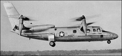
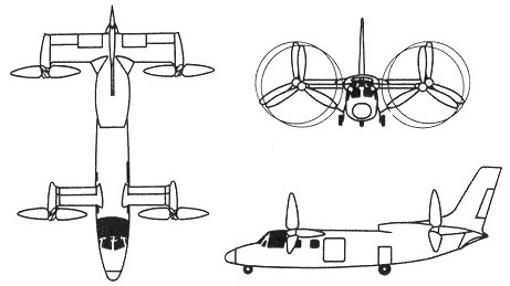
The Curtiss-Wright X-19 began as a commercial venture to develop a small, 4-passenger, executive VTOL aircraft that would have good high speed performance. Funded initially by Curtiss-Wright, it was designated the M-200. With solid test results from the X-100 confirming their theories regarding the potential for a practical application of radial lift, Curtiss-Wright pressed on with the design of the M-200. Design trade-off studies were performed which ultimately led to the X-19’s tandem wing configuration with a tilting propeller at each wing tip. The X-19 started with what Curtiss-Wright engineers felt was the optimal design for a propeller for a VTOL aircraft and then built the aircraft around it. The propellers had a very wide chord with a large amount of twist. This allowed them to maximize the amount of radial lift. At the start of the program, Curtiss-Wright funded the entire effort, with no interest in any government support. Two prototypes were being built when new management at Curtiss-Wright decided they no longer wanted to invest company research funds. They offered the two aircraft to the Tri-Service VTOL Program, a joint Air Force, Army, and Navy program office tasked with developing VTOL technologies for military needs. The Tri-Service Program also was developing the XC-142 and the X-22. Eighteen months later the Air Force agreed to buy the aircraft. When the Tri-Service Program bought the X-19s, the two prototypes already were 55 percent and 35 percent complete, with a substantial investment already having been made by Curtiss-Wright. The original X-19 design, as the M-200, was not built to any specific mission requirement. The goal was to fly as fast and far as possible and to be economically competitive with conventional executive transports that were becoming very popular in the 1960s. Analysis of the design showed that the M-200 could achieve a range of 1450km to 1850km with a maximum level speed of 740km/h at 4880m. It was to conform to FAA regulations, have all weather flying capability, low noise level, and be free of vibration. Conventional aircraft construction techniques and materials were used.
The X-19’s basic configuration was an all-metal, monocoque fuselage, with two shoulder-mounted tandem wings. A nacelle at each wing tip could rotate from pointing vertically for take off and landing to pointing horizontally for cruise. The wide, specially-designed propeller was mounted in front of each nacelle. Two turboshaft engines housed in the rear fuselage powered the four props. The fully hydraulic tricycle landing gear retracted completely into the fuselage. A large vertical tail was required because the props were located relatively close to the fuselage. Total height was just over 5m. The original fuselage was 12.5m long, but the cabin area was only 1.2m high, 1.4m wide, and 2.4m long. The passenger compartment was intended for four passengers, or 450kg of cargo. The cabin was pressurized to 4880m. All fuel was stored in the fuselage, aft of the passenger/cargo area. There were two 860 lt tanks and one 990 lt tank. The front wing had a 6.1m span with a narrow chord, while the rear wing had a 6.4m span with a greater chord. The rear wing had almost twice the area of the front wing. The wings had no incidence, dihedral, or sweepback. The front wing incorporated full span flaps, while the rear wing had inboard ailerons and outboard elevators, the ailerons being slightly larger than the elevators. The flaps on the front wing were directly coupled to the nacelle tilt angle, and the pilot could not control them independently. At hover, the flaps and elevators drooped to their full extension of 60 degrees to decrease the amount of wing area that was in the prop downwash. The location of the props on wing tips, however, resulted in the loss of 7 to 9 percent of lift due to wing interference. Curtiss-Wright intended originally to use four Wankel rotary engines rated at 580hp each. Curtiss-Wright eventually abandoned the Wankel in favor of two Lycoming T-55-5 turboshaft engines of 2200hp each (although some sources stated T-55-L-7 engines of 2650hp each). This more than doubled the total power, but retained the ability to operate with one engine failed, including performing vertical take-offs and landings. Switching from four engines to two also simplified the design by decreasing the engine interconnects, and changing to turboshaft engines eliminated the need for engine cooling. Power from the engines was distributed to the props by means of three-inch diameter drive shafts and seven gear boxes. The gear boxes consisted of one engine coupling box that coupled the two engines so that either could power the entire system, two T-boxes to transfer power from the fuselage shafts into the wing shafts, and four nacelle tilt gear boxes. The exhaust pipe from each engine joined in the fuselage so that only one pipe exited the rear of the aircraft. The 4m diameter props construction consisted of a steel shank, foam core, and fiberglass shell. The paddle-wheel shape allowed them to produce about 2.7kg of thrust per horsepower. Low prop noise was obtained because the maximum tip speed of 250m/s was well below sonic speed. The cockpit accommodated two pilots seated side by side. The aircraft could be flown from either seat, but the pilot-in-command seat was on the right, as in a helicopter. The cockpit resembled that of a conventional aircraft, with the cockpit visibility being very limited for a VTOL aircraft. The high instrument panel also restricted vision over the nose. Two one-foot square windows were located near the pilots’ feet, but were too small to be effective and later were modified into ram air inlets to provide additional cooling. Each pilot had a conventional stick, rudder pedal, and two throttles. Nose wheel steering was by means of a hand tiller controlled by the copilot. To minimize the clutter on the instrument panel, there was a single oil temperature gauge and single oil pressure gauge for all nine gear boxes. The pilot could select which component to monitor by rotating a 9-way selector switch to the desired component. To signal a problem, each gear box had a single warning light that indicated either high or low oil pressure, or the presence of metallic chips in the oil. If the light illuminated, the pilot had to rotate the 9-way switch to see the specific problem. When rotated to the vertical positions, the front nacelles rotated past vertical, to 97 degrees, meaning the thrust actually pointed slightly forward. The rear naceltes rotated only to 82 degrees with their thrust pointing slightly rearward. A tilt button on the control stick caused all nacelles to tilt together. Initially, the nacelle tilt rate was mechanized at 5 degrees per second. It was soon realized that this would have required a deceleration from 90km/h to hover in less than 5 seconds, resulting in 0.5g of longitudinal acceleration. This was too much, so the rate was reduced to 1 degree per second, resulting in a more reasonable 0.2g. Two independent hydraulic systems controlled the nacelle rotation and prop blade angles. If the automatic system failed, the pilot could rotate them manually using a hand crank. The crank required 570 turns to move the nacelles from end to end, and eventually was replaced with a motor. The Tri-Service Program required a few changes to convert the M-200 into the X-19. North American Aviation LW-2B ejection seats, which used a rocket catapult mechanism and ballistically deployed parachutes, were added. These seats could operate from zero altitude and zero airspeed up to 15250m and deploy fully within 0.5 second from seat firing. The seats ejected through the canopy. The fuselage was lengthened by 0.9m so that two more passenger seats could be added, bringing the total personnel load up to two pilots and six passengers. This increased the fuselage length to 13.5m. The cabin door was enlarged to 1.06m high and 1.17m long, and a rescue hoist was added. The resulting aircraft was a bit long for a six passenger aircraft, but this was attributed mostly to the engines and fuel tanks being located in the fuselage. The only difference between the two prototypes was that the second had better instrumentation and data recording, and also had a dummy refueling probe installed on the nose to evaluate probe and drogue in-flight refueling. Weight growth after adding the ejection seats and stretching the fuselage resulted in the useful load being reduced to 185kg. This allowed for only one pilot and fuel for 10 minutes of hovering. With two pilots, the hovering time was cut to 1 minute. However, there was still 270kg of unusable fuel because of the location of the fuel pumps inside the tanks. The pump position was changed to improve the amount of usable fuel. The X-19 was statically unstable in hover and in pitch and roll at low speed, mandating the addition of stability augmentation in both of these axes. Control by the augmentation system was limited to 30 percent of the pilots’ control authority, so the pilot could override it if necessary. No stability augmentation was needed for yaw. The system initially mechanized rate feedback, but initial testing showed this to be of little use to pilot. The system was changed to a rate plus integral of rate, which improved control for hover and low speed flight. The X-19 was test flown with the stability augmentation turned off. Although it was controllable by the pilot, the workload was unacceptable. All gear boxes were designed to absorb the power required to lift the aircraft at a maximum weight of 5540kg. Great difficulty was encountered in qualifying them, and very low life limits were established in order to conduct flight tests. The engine coupling gear box, which combined the power output of the two engines, was capable of absorbing 2,900 horsepower with both engines running, or 2500hp from only one engine. With each engine producing 2200hp (or 2650hp, depending on the reference), the gear box obviously could not absorb full power from both engines. In addition, it was limited to 50 hours of operation. Likewise, the nacelle gear boxes had estimated lives of 13-14 hours and were thus limited to 5 hours of operation. The problem was felt to be improper heat treating of the gears. Wind tunnel tests of the initial design indicated an unacceptably high amount of interference drag at the junctions of the wing/fuselage and wing/nacelle. Drag clean up measures were taken, and more wind tunnel tests were run to confirm the improvement. The rear wing had significant lift loss due to downwash from the front wing, but knowing this, it was compensated for in the basic design. Airframe structural tests revealed no major problems. Full scale static propeller tests were performed to evaluate and reduce download losses on the wing at hover. The intended design empty weight was 3600kg with a gross take-off weight of 5540kg. However, the empty weight grew to 4800kg and the gross take-off weight to 6160kg by the time the aircraft was built, thus reducing the useful load and placing greater stress on the gear boxes. Most of the weight growth came from the fuselage, wings, and power transmission system. It is safe to assume that Curtiss-Wright engineers started their fuselage and wing designs using standard practices for a conventionally configured aircraft, but stress analyses indicated weaknesses peculiar to the tandem design and prop locations. The fuselage had to be heftier than originally expected to handle the loads imposed by the landing gear location and the tandem wing configuration. The wings also had to be heftier than normal because during hover, all lift came from the props at the wing tips, rather than the lift being distributed along the wing as on a conventional aircraft. Also, the wings had to be very stiff so as not to transmit any propeller vibration. The shafting and gear boxes also proved to be heavier than predicted. Altitude was controlled during hover by the throttle, and precise control was difficult because of a lag of nearly one second in the engine response time. Varying the pitches of the four props controlled pitch and roll. A unique prop rotation scheme was used to maximize propeller torque for yaw control…the props on opposite corners turned in the same direction. A yawing moment resulted from the blade angle being increased on one corner and decreased on the opposite corner. The pilot didn’t control the blade angles directly, but used the rudder pedals for yaw and the stick for pitch and roll inputs. A mixer in the flight control system automatically controlled the actual commands to the individual props. To initiate a transition from hover to horizontal flight, the pilot pressed the tilt button on the stick to start the nacelles rotating, then added throttle to increase lift, accelerate, and maintain altitude or climb. As altitude and speed increased, the pilot continued to lower the nacelles until reaching 295km/h, at which time the transition was complete and the X-19 would fly like a conventional aircraft. Throughout the transition, the mixer continuously faded out prop control and faded in conventional control surface control as the airspeed increased. To reverse the transition, the process was reversed.
Roll out of the first prototype, tail number 62-12197, occurred on July 23, 1963. The flight test approach was to demonstrate hover, transition, and finally forward flight. Curtiss-Wright pilots would fly the initial flights, demonstrating hover and transition. After that, a Tri-Service test team would take over. The first flight was performed on November 20, 1963, at Curtiss-Wright’s facility at Caldwell, NJ. The X-19 lifted off for only a few seconds in hover before settling and collapsing a main gear because of side loads. Although the damage was minor, it was seven months until the X-19 flew again. The Air Force wanted to send the X-19 to Edwards AFB. Curtiss-Wright argued that supporting the test program at Edwards would be difficult, and that in an emergency, the X-19 would land vertically, making the long runway and large dry lake bed unnecessary and a waste of taxpayers’ money. The Air Force finally agreed that flights up through transition would be done at Caldwell, NJ, but the remainder of test flights would be performed at Edwards. Flight testing resumed on June 26, 1964. The X-19 made numerous hovers, most only a few seconds in duration. By August 7, it had flown on twelve different days and accumulated one hour and 37 minutes, accomplishing most of the objectives planned for its first eight hours of hover testing. The X-19 demonstrated spot turns, lateral translations at speeds up to 28km/h, rearward flight at 19km/h, forward flight at 37km/h, and 50 take-offs and landings. During these tests, the X-19 proved difficult to control, requiring excessive pilot workload. Various combinations of stick breakout and gradient forces were tried, but produced no improvement. However, the pilots were improving their skills at such a fast rate as they gained experience that it was difficult to determine if improved performance was from increased experience or the control system improvements. On the 21st flight, the stability augmentation system was turned on, which made hovering much easier. Flight speeds up to 160km/h were obtained with good flight characteristics up to this speed. On November 12, the X-19 experienced a full pitch hardover caused by the stability augmentation system. The pilot retained control because of the limited authority of the stability augmentation system and deactivated it. On the next day, they experienced a roll hardover. The cause of these incidents never was determined conclusively. On December 4, 1964, the X-19 suffered damage from loose cinders on the runway, which had just been resurfaced. Both engines and the leading edges on all four props were damaged. On January 31, 1965, one prop failed, which forced suspension of further testing for six months. While repairs were being made, it was decided that testing should be moved to the Federal Aviation Administration’s National Aviation Facilities Experimental Center (NAFEC) near Atlantic City, NJ. On July 31, 1965, the X-19 hovered for an air worthiness test after six months of down time, following which the props were removed and the aircraft was shipped to NAFEC. The X-19 was reassembled quickly and soon was flying again at NAFEC. Throughout August 1965, it made numerous high speed hovers going more and more into the transition. At this point, the Air Force test team joined the program. The Air Force test pilot quickly determined that the remaining control problems during hover were caused by excessive and uneven hysteresis in the control stick. Hysteresis is the tendency of the stick and control surfaces not to return to their original position when the pilot moves the stick then lets go (it is caused by friction between all the moving parts and stretching of control cables). Pitch hysteresis was found to be 4 to 8 percent of total displacement, and lateral hysteresis was 12 to 25 percent. Pilots had to make much bigger roll inputs than pitch inputs, resulting in poor control harmony and the pilot getting out of phase with the aircraft’s motions. This problem was corrected, and hovering became much easier. The first full transition was planned for August 25, 1965, on flight number 50. As the X-19 climbed and accelerated, the nacelles tilted as far as 65 degrees from vertical as the aircraft reached 150km/h at 400m. At this point, the temperature warning lights for left rear nacelle gear box and aft T-box illuminated. The pilots terminated the test and began a return to the airport. An immediate, emergency landing did not appear warranted, and the pilots planned a normal approach based on the recommendation from the ground support team. As they circled to line up with the preferred runway, a very high frequency vibration and a low frequency random shake began. Lateral control began to deteriorate. With the X-19 pointed toward a wooded area at low altitude and fearing that they would not clear the trees, the copilot jammed the throttles forward. As they climbed and accelerated, some control was regained and the vibrations smoothed out. At 120m, the left rear prop snapped off, and the X-19 rolled to the left and pitched up. This was followed promptly by the separation of the left front prop, then the two right props. The pilots bailed out inverted, their parachutes deploying fully within 2 seconds at an altitude of 70m. The aircraft crashed into a nearby swampy area and was totally destroyed. The pilots suffered only minor injuries, mostly cuts from ejecting through the canopy. The time from loss of props to ejection was only 2.5 seconds. The cause of the crash was attributed to the copilot’s applying full power. The drive system could not absorb the 4400hp being generated, resulting in the failure of the prop gear box. Total flight time for the flight was only seven minutes.
The crash itself did not end the X-19 program. The Air Force wanted to continue with testing the second prototype, which was nearing completion, but wanted to switch to a fixed price contract. Curtiss-Wright did not like that, because they would now take all financial risk. Their management also saw no future business in a commercial VTOL transport, even if the X-19 ultimately proved successful. They refused the Air Force’s offer. Unable to come to any agreement, the program ended in December 1965.
The X-19 completed 129.4 hours ground running time and flew a total of 3.85 hours. The second X-19 never flew and eventually was cut up for scrap.
Curtiss-Wright X-19A Engines: two 2,200-shp (1640-kW) Avco Lycoming T55-L-5 turboshafts Wingspan: 10.5m Length: 13.5m Height: 5.2m Wing area: 14.4 sq.m Take-off weight: 6200kg Empty weight: 4400kg Max speed: 720km/h Cruising speed: 650km/h Range with max fuel: 1200km Crew: 2 Passengers: 4 Payload capacity: 550kg