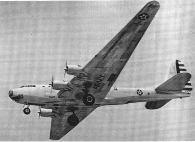
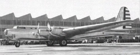
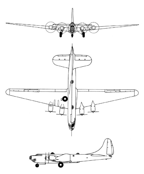
Originally designated XBLR-2 (eXperimental Bomber Long-Range 2), the XB-19 was essentially used as a test bed for very large bomber construction techniques and flight characteristics. The Douglas Aircraft Company had wanted to cancel the project because of the expense and extended construction time which made the aircraft obsolete before it ever flew. However, the Army Air Corps insisted the aircraft be completed for test use. The XB-19’s first flight was 27 June 1941, more than 3 years after the construction contract was awarded. In 1943, the original radial engines were replaced by Allison V-3420 in-line engines and the aircraft was redesignated XB-19A. After testing was completed, the XB-19A was used as a cargo/transport aircraft until 1949 when it was scrapped.
Engines: 4 x 2000hp Max take-off weight: 73467 kg/ 161968 lb Wingspan: 64.62 m / 212 ft 0 in Length: 40.23 m / 131 ft 12 in Height: 13.03 m / 42 ft 9 in Max. speed: 360 km/h / 224 mph Ceiling: 7015 m / 23000 ft Range: 8372 km / 5202 miles Crew: 11 Armament: 2 x 37mm cannon, 5 x 12.7mm + 6 x 7.62mm machine-guns , 16330kg of bombs
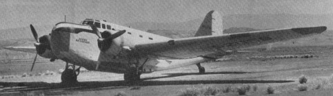
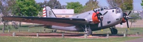
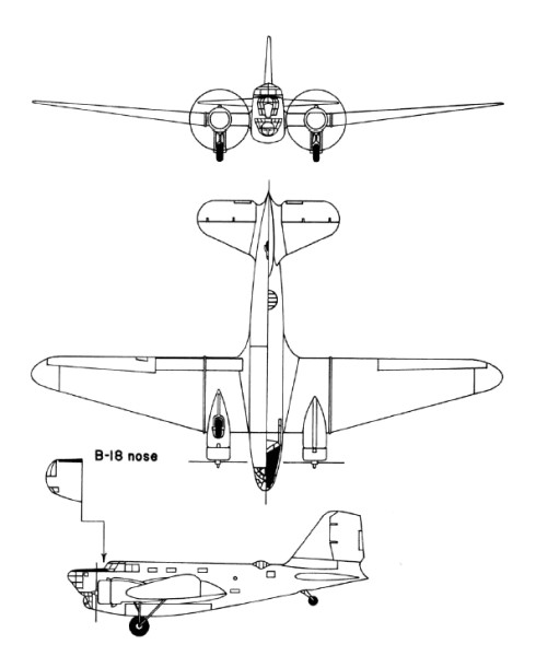
With a 1934 US Army Air Corps requirement for a bomber with greater capability than their Martin B-10, Douglas drew on engineering experience of the DC-2 commercial transport. Private-venture prototypes to meet the US Army’s requirements were evaluated at Wright Field, Ohio, in August 1935, these including the Boeing Model 299, Douglas DB-1 and Martin 146. The first was built as the B-17 Flying Fortress, the last was produced as an export variant of the Martin B-10/B-12 series, and the Douglas DB-1 (Douglas Bomber 1) was ordered in January 1936 into immediate production under the designation B-18. Derived from the commercial DC-2, the DB-1 prototype retained a basically similar wing, tail unit and powerplant. There were two differences in the wing: while retaining the same basic planform as the DC-2, the DB-1 had a 1.37m increase in span and was mounted in a mid-wing instead of low-wing position on an entirely new fuselage. The fuselage was deeper than that of the commercial transport to provide adequate accommodation for a crew of six, and to include nose and dorsal turrets, a bomb-aimer’s position, and an internal bomb bay. There was a third gunner’s position, with a ventral gun discharging via a tunnel in the underfuselage structure. Power was from two 694kW Wright R-1820-45 Cyclone 9 engines. 133 B-18s were covered by the first contract, including the single DB-1 which had served as a prototype. Production aircraft, which had the type name Bold, had equipment changes producing an increase in the normal loaded weight, and more-powerful Wright R-1820-45 radials. The last B-18 to come off the production line differed by having a power-operated nose turret, and carried the company identification DB-2, but this feature did not become standard on subsequent production aircraft. A second contract covered 217 B-18A aircraft, placed in June 1937 (177) and mid-1938 (40). This version differed by having the bomb-aimer’s position extended forward and over the nose-gunner’s station, and the installation of more-powerful Wright R-1820-53 engines. Most of the USAAC’s bomber squadrons were equipped with B-18s or B-18As in 1940, and the majority of the 33 B-18As which equipped the USAAC’s 5th and 11th Bomb Groups, based on Hawaiian airfields, were destroyed when the Japanese launched their attack on Pearl Harbor. When in 1942 B-18s were replaced in first-line service by B-17s, 122 B-18As were equipped with search radar and magnetic anomaly detection (MAD) equipment for deployment in the Caribbean on anti-submarine patrols under the designation B-18B. The Royal Canadian Air Force also acquired 20 B-18As which, under the designation Digby Mk I, were employed on maritime patrol. The designation B-18C applied to two other aircraft reconfigured for ASW patrol. Another two aircraft were converted for use in a transport role under the designation C-58, but many others were used similarly without conversion or redesignation.
B-18A Engines: 2 x Wright R-1820-53 Cyclone 9, 746kW / 986 hp Max take-off weight: 12552 kg / 27673 lb Empty weight: 7403 kg / 16321 lb Wingspan: 27.28 m / 89 ft 6 in Length: 17.63 m / 57 ft 10 in Height: 4.62 m / 15 ft 2 in Wing area: 89.65 sq.m / 964.98 sq ft Wing loading: 28.70 lb/sq.ft / 140.0 kg/sq.m Max. speed: 187 kts / 346 km/h / 215 mph Cruise speed: 145 kts / 269 km/h / 167 mph Service ceiling: 7285 m / 23900 ft Range: 1043 nm / 1937 km / 1204 miles Armament: 3 x 7.62mm (0.30in) machine-guns, 2948kg of bombs Crew: 6
In the late 1920s the US War Department ordered two Fokker XO-27 prototypes. Fearing it might lose a valuable source of revenue, Douglas designed an aircraft incorporating all-metal cantilever monoplanes with retractable landing gear features and in March 1930 received an order for one example each of the Douglas XO-35 and Douglas XO-36. They were intended to differ only in their engines, the former having geared Curtiss Conquerors and the latter a direct-drive version of the same engine. In the event, the XO-36 was redesignated XB-7 and built as a bomber. In a parallel development the second of the Fokker XO-27s was completed as the XB-8 bomber. Later, six YO-27s and six Y1O-27s were delivered to the US Army.
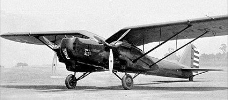
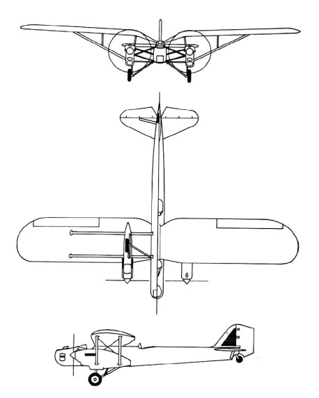
The Douglas XO-35 was test-flown in spring 1931. It was a monoplane with a gull wing set high on the fuselage, the main units of its landing gear retracting into streamlined engine nacelles leaving only the lower part of the wheels exposed. The engine nacelles were attached to the wing undersurfaces and fuselage sides by complex strut assemblies, and the fuselage having corrugated metal sheet covering. There were open gunners’ cockpits in the nose and amidships; the pilot’s open cockpit was located immediately forward of the wing leading edge; and the fourth crew member, the radio-operator, had an enclosed cabin behind the pilot’s position. The XB-7 was almost identical, but had underfuselage racks for up to 544kg of bombs. During the US Fiscal Year 1932 orders were placed for seven Y1B-7 and five Y1O-35 service-test aircraft. These differed from the prototypes mainly by having smooth metal sheet covering for the fuselages, and strut- rather than wire-braced horizontal tailplanes. The Y1B-7s, later designated B-7, were attached to the two US Army bombardment squadrons based at March Field, California, while the O-35 aircraft (previously Y1O-35s) flew with observation units. In February 1934 the five O-35s, six surviving B-7s and XO-35 prototype were all assigned to the air mail route linking Wyoming with the west coast of the United States. Operations at night and in bad weather took their toll and in the four-month emergency period during which the US Army ran the nation’s air mail service no fewer than four of the B-7s were lost in crashes. Soon afterwards the remaining B-7s and O-35s were relegated to second-line duties, an O-35 being the last to be grounded in February 1939.
B-7 Crew: 4 Engine: 2 x Curtiss V-1570-53 Conqueror, 503kW Max take-off weight: 5070 kg / 11177 lb Loaded weight: 2503 kg / 5518 lb Wingspan: 19.81 m / 64 ft 12 in Length: 14.0 m / 45 ft 11 in Height: 3.53 m / 11 ft 7 in Wing area: 57.71 sq.m / 621.18 sq ft Max. Speed: 293 km/h / 182 mph Cruise speed: 254 km/h / 158 mph Ceiling: 6220 m / 20400 ft Range: 660 km / 410 miles Armament: 2 x 7.62mm machine-guns, 540kg of bombs
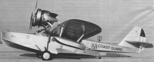
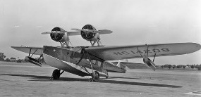
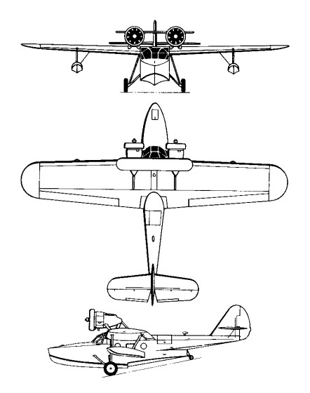
Completed in July 1930 as the non-amphibious Sinbad under civil registration NX145Y, Douglas’s first in-house flying boat design was initiall concieved as a “flying yacht” to be offered on the civilian market. The Sinbad appeared as a monoplane having an all-metal hull of semi-monocoque construction and a two-spar cantilever wing covered in plywood that featured slotted, Handley Page type ailerons. In original configuration, the 300-hp Wright J-5C Whirlwind engines were mounted directly above the wing and encased in nacelles that blended-in with its upper surface.
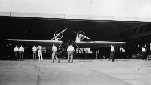
Several men examine Douglas Aircraft Co.’s new amphibian plane “Sinbad” at Clover Field (Santa Monica Airport). She became the prototype for the Dolphin series. Photo taken on July, 17, 1930, around the time of its first flight.
After flight testing revealed the need to raise the thrust line, the engines were moved above the wing on struts, along with an auxiliary airfoil mounted between the conical engine nacelles to add structural support and lift. When no civilian buyers surfaced, the Sinbad was sold to the Coast Guard in March 1931 for $31,500, where it operated for a period of time as call-sign “24 G” without a military designation but later simply listed as the “RD” with no numeric suffix.
Sinbad after Modifications
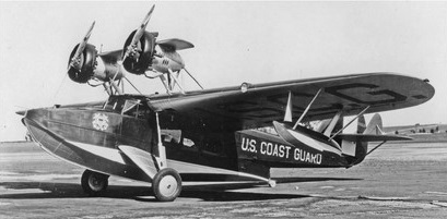
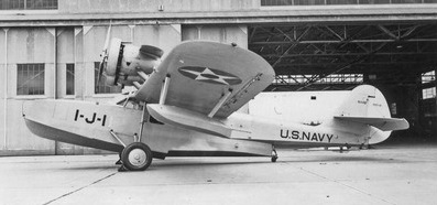
The improved Dolphin, equipped with amphibious landing gear, a modified hull, and 400 hp Pratt & Whitney R-1340 engines, emerged in early 1931 and two, known as the Dolphin I Speccial, were sold n June the same year to the Wilmington-Catalina Airline where they completed close to 40,000 crossings without incident. Military orders followed for 350 hp R-975 Whirlwind powered examples for the US Army Air Corp and another to the Navy as the XRD-1, both delivered in late 1931. Twenty-three more Dolphin variats were procured for the navy and the Coast Guard between 1932 and 1934; three RS-2s in early 1933, two to the Navy and one to the Coast Guard, powered by 450 hp Pratt & Whitney R-1340 engines; six very similar RD-3s in mid-1933 to the Navy; and ten RD-4s in late 1934 to the Coast Guard, powered by 450 hp R-1340-96 engines. One of the Navy RD-2s was specially outfitted for President Franklin D. Rooservelt but there is no record of it being used for such purpose. Navy RDs were assigned to utility squadrons and used primarily as transports, whereas Coast Guard versions saw extensive service in the search and rescue role as flying lifeboats. Two RD-3s were subsequently assigned to the Marine Corps to be used as utility transports. One aircraft reportedly manufactured as an RD-2 was used as a government transport by the Secretary of the Treasury until 1937. After the US entered World War II, RD-4s remaining in service with the Coast Guard were employed briefly for coastal patrol duties.
The authorities are in conflict as to the exact number of Dolphins accepted by the US Army Air Corp, however, it appears at least sixteen were delivered between 1932 and 1933. Two in 1932, powered by 300 hp Pratt & Whitney R-985 engines, eight in 1932 powered by 350 hp R-985-5 engines, as the C-26A; four in 1932-33, powered by 350 hp R-985-9 engines, as the C-26B, and two with enlarged cabins in 1933, powered by 575 hp R-1349-16 engines, as the C-29.
RD-2
In 1936-37 four OA-4As and one OA-4B were refitted with stainless steel wings, thn another OA-4B became the OA-4C when modified with experimental tricycle landing gear.
Civilian Dolphins, of which sixteen (including the two Dolphin I Specials) are estiated to have been built between 1933 and 1934, came in many variations ae decreaed by the preferences of individual customers. One registered as NC14286 was completed as a personal transport for William E. Boeing. French industrialist Armand Esders purchased a Dolphin powered by two 550 hp R-1340-51 engines, Standard Oil Company acquired two with 450 hp R-1340-56 engines to be used in overseas operations, and two more were built for the Vanderbilt family. In 1934 Pan American Airways bought two Dolphins that were operated by China National Airways Corp subsidary. After World War II began, one Dophin I Special and one from Standard Oil ended up flying in Australia with the RAAF.
RD-4 Engines: 2 x Pratt & Whitney R-1340-96 Wasp, 450 hp Props: 2 blade, ground adjustable, metal Wingspan: 60 ft 10 in / 18.29 m Wing area: 592 sq.ft / 55.0 sq.m Length: 45 ft 3 in / 13.74 m Height: 14 ft / 4.27 m Empty weight: 7000.9 lb / 3175.0 kg Gross weight: 9737 lb / 4323.0 kg Max speed: 147 mph / 136 kts / 251 km/h Cruise speed: 110 mph / 117 kts / 217 km/h Ceiling: 14,900 lb Range: 660 mi Seats: 8
C-21 Engine: 2 x Wright R-975-3, 261kW Max take-off weight: 3893 kg / 8583 lb Loaded weight: 2659 kg / 5862 lb Wingspan: 18.29 m / 60 ft 0 in Length: 13.36 m / 43 ft 10 in Height: 4.29 m / 14 ft 1 in Wing area: 52.21 sq.m / 561.98 sq ft Max. speed: 225 km/h / 140 mph Cruise speed: 192 km/h / 119 mph Ceiling: 4330 m / 14200 ft Range: 885 km / 550 miles
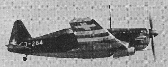
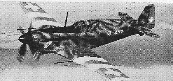
Swiss fighter aircraft. In 1938 the Swiss government purchased two Morane Saulnier M.S.405 fighters from France and, after careful evaluation, purchased a licence for the production version, the M.S.406C. Manufacture of a Swiss version of the 406 was assigned to Dornier Flugzeug at Altenrhein, with the Swiss designation D 3800. This differed from the French aircraft in having a Saurer/SLM licence built Hispano Suiza 12Y 31 of 860 hp, cooled by a fixed ventral radiator.
In 1939 40 Dornier delivered 82, followed in 1940 44 by 207 D 3801 fighters with many refinements and in having the 860 hp Hispano 12Y-31 engine replaced by a 1000 hp Hispano 12Y-51 built by A.G.Adolph Saurer.. Both types had one 20 mm (0.79 in) Hispano cannon and two 7.7 mm (0.303 in) wing guns, with provision for two 50 kg (110 lb) bombs.
D-3801
The D 3802 single-seat fighter prototype was built in 1943 by Dornier Werke to designs provided by Morane-Saulnier (designated M.S.450). A second prototype modified up to production standards was produced as the D-3802A, and orders were placed by the Swiss Air Force for 100. With the end of the war in Europe, the order was reduced to ten, built in 1944.
D-3802A
The 1500 hp (12Y 53) D 3803 of 1947 remained a one off, by which time the company had become Flug & Fahrtzeug¬werke (F&FW).
D 3801 Engine: 1000 hp Hispano 12Y-51 Span: 10.61 m (34 ft 9.75 in) Length: 8.16 m (26 ft 9.25 in) Empty weight: 4694 lb Gross weight: 2725 kg (6007 lb). Maximum speed: 523 km/h (325 mph) at 13,950 ft Econ cruise: 190 mph Time to 16,400 ft: 5.4 min Service ceiling: 35,400 ft
D-3802A Engine: Hispano-Suiza 1250 hp 12Y-52 Wingspan: 35 ft 2.75 in Length: 30 ft 7 in Height: 10 ft 11 in Empty weight: 6327 lb Loaded weight: 7716 lb Max loaded weight: 8014 lb Max speed: 391 mph at 21,325 ft Time to 19,865 ft: 7.1 min Ceiling: 33,500 ft Armament: three 20mm (0.79 in) cannon
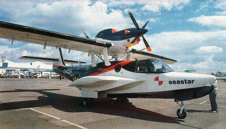
Dornier succcessfully test flew preproduction Sea Star CD2 with technical modifications in 1988. Modifications included – Increase in wing area from 28.5 to 30.5 sq.m. Replacement of the original P&WC PT6A-112 engines with –13S models of 650 hp at takeoff and 500 hp at cruise. This led to a 400 kg gain in takeoff weight, better climb rate, and up o 11 hrs in single engine (600 hp) mode. Addition of a small keel on the underside of the hull, resulting in greater stability and reduced takeoff and landing speeds. Modifications to the upper strut shrouds and air intakes, allowing an increase in empty weight, from 2.6 to 2.8t, and rise in payload capacity, from 1.6 to 1.8 t.
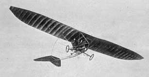
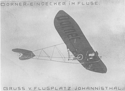
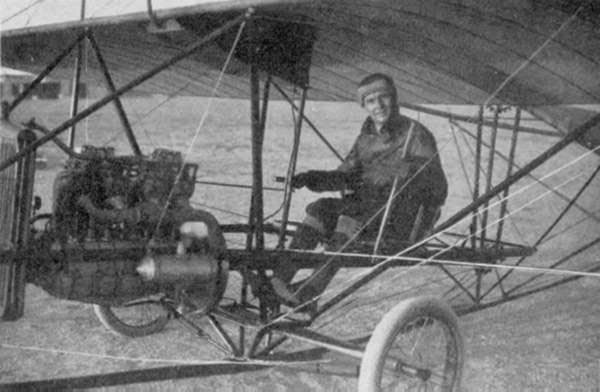
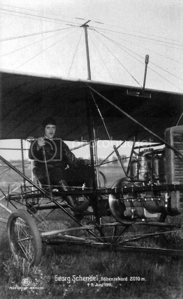
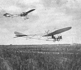
The Dorner monoplane was a well-known sight around Johannistahl. Georg Schendel set a German record for altitude of 2010 meters on 6 June, 1911, and a World Altitude record with passenger, of 1690 meters on 9 June, 1911, in his Dorner.
Type II had a 20 hp Dorner-Motor and cost 13,500 Marks.
Type III came with a 40 hp Dorner-Motor at 15,500 Marks, or 50 hp at 16,500 Marks.
1911 model T III – Dixi engine
Dorner had entered the T III with 40 hp Körting at the “Zuverlässigkeitsflug am Oberrhein” in April/May 1911, where his light monoplane still was underpowered and could not complete a single stage.
The T. III version had a fatal accident for both passenger and pilot on 9 June, 1911 at Johannistahl.
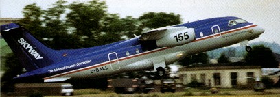
A twin jet regional transport aircraft. In 1999, Fairchild Aerospace announced that it had taken an order from Lufthansa for 60 of its all new 70 passenger 728 jets the carrier also reserved 60 options for the jet.
728JET Engines: two 12,500 lb. General Electric CF343-3D1 turbofans. Gross weight: 83,754 lbs. Max cruise: 460 kts Range: 1,400–4,000 nm Service ceiling: 41,000 ft. Takeoff distance: 4,800 ft. Landing distance: 4,659 ft. Seats: 70