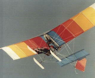
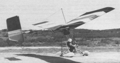
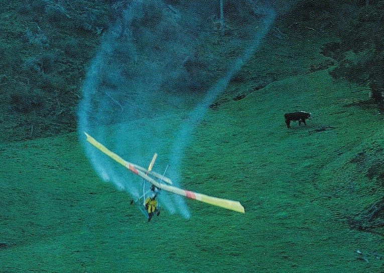
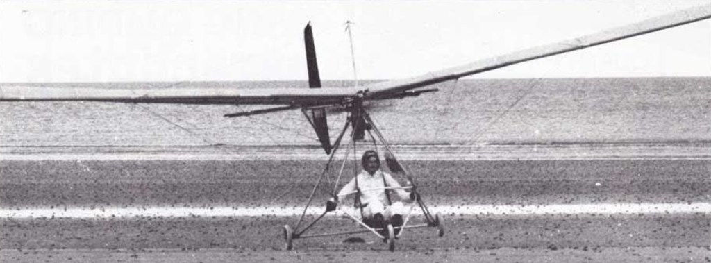
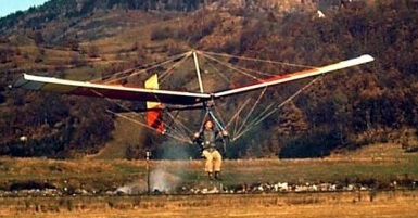
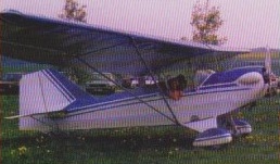
The Quicksilver GT was an entirely new concept from the Eipper company. Introduced in 1984 it was available in two versions. The 280C, a cable braced like all other Eipper ultralights while the 280S was strut braced. The double surface wings are tappered and have flaps and ailerons fitted. The two piece aluminium boom supports the pilot forward of the main plane in a sleek cockpit pod. Centre mounted yoke, rudder pedals, nosewheel steerable through rudder pedals. The GT entered production in 1984.
The Quicksilver monoplane hang glider was developed it into a powered glider. With its twin-boom tail support structure, an engine mounted from the wing center section it offers gentle and forgiving flight characteristics and is generally foot-launched, though landing gear can be added. The first powered version being the Quicksilver M.
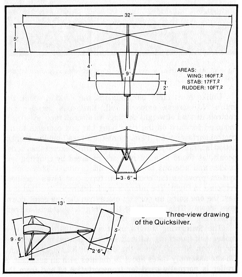
The Quicksilver E is a single seat single engined high wing monoplane with hybrid control. Wing has unswept leading and trailing edges, and constant chord; cruciform tail. Pitch control by elevator on tail, assisted by weight shift; yaw control by fully flying rudder, assisted by weight shift; no separate roll control; control inputs through weight shift for pitch/yaw/roll. Wing braced from above by kingpost and cables, from below by cables; wing profile single surface. Undercarriage has three wheels in tricycle formation; with additional tailskid; torsion bar suspension on all wheels. No ground steering. No brakes. Aluminium tube framework, without pod. Engine mounted below wing driving pusher propeller.
Quicksilver E
Motorization was a logical step, since the Quicksilver hang glider already had hybrid control, with its rudder linked by cables to the pilot’s harness. The hybrid version of the Quicksilver, the E, made its appearance in May 1982 and doesn’t have a great many points in common with the early hybrids from this manufacturer. It uses the tricycle undercarriage frame developed for the MX. The pilot’s swing seat is connected to the rudder on the cruciform tail and also to a ‘trimvator’ elevator measuring 4 x 42 inch (10 x 107 cm), hinged from the trailing edge of the horizontal stabiliser. These elevators work to assist the weight shift control of the pilot.
Units delivered to June 1981: 5,000. The type E is delivered as a kit requiring 15 h for assembly at a price of $3995 in the US in 1982. As well as the options available for the other single seaters from Eipper Aircraft, the type E, which is fitted with a Cuyuna 215R 20 hp engine, can have the 430R 30 hp engine or one of the Rotax engines, options which are becoming increasingly popular.
Quicksilver Double quick and Seaquick types were all hybrid control like the type E.
Quicksilver E Engine: Cuyuna 215R, 20 hp at 5500 rpm. Propeller diameter and pitch 52 x 32 inch, 1.32 x 0.81 m. V belt reduction, ratio 2.25/1. Power per unit area 0.13 hp/sq.ft, 1.3 hp/sq.m. Fuel capacity 2.5 US gal, 2.1 Imp gal, 9.5 litre. Length overall 18.1 ft, 5.51 m. Height overall 9.8ft, 2.93m. Wing span 32.0ft, 9.75m. Constant chord 5.0ft, 1.52 m. Dihedral 15 degs. Sweepback 0 degs. Tailplane span 9.1 ft, 2.75 m. Total wing area 160 sq.ft, 14.9 sq.m. Rudder area 11.3 sq.ft, 1.05sq.m. Tailplane area 19.5 sq.ft, 1.82sq.m . Total elevator area 1.1 sq.ft, 0.11 sq.m. Wing aspect ratio 6.4/1. Wheel track 5.9ft, 1.75 m. Wheelbase 5.5ft, 1.66 m. Nosewheel diameter overall 12 inch, 30 cm. Main wheels diameter overall 12 inch, 30 cm. Empty weight 195 lb, 88kg. Max take off weight 415 lb, 188kg. Payload 220 lb, 100kg. Max wing loading 2.59lb/sq.ft, 12.6 kg/sq.m. Max power loading 20.7 lb/hp, 9.4kg/hp. Max level speed 42 mph, 67 kph. Never exceed speed 60 mph, 97kph. Max cruising speed 34mph, 54kph. Stalling speed 19 mph, 30 kph. Max climb rate at sea level 450 ft/min, 2.2 m/s. Min sink rate 320ft/min, 1.6m/s. Take off distance 60ft, 18m. Landing distance 50ft, 15m. Service ceiling 9000ft, 2745m. Range at average cruising speed 68 mile, 109km.
The popular Quicksilver monoplane hang glider was developed it into a very good power glider. With its twin-boom tail support structure, an engine mounted from the wing center section it offers gentle and forgiving flight characteristics and is generally foot-launched, though landing gear can be added.
Quicksilver B
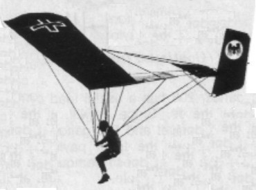
The origin of the Quicksilver can be found in Bob Lovejoy’s High-Tailer design. The High-Tailer and early Quicksilvers all had a 4 foot chord and 30 ft span.
The original Quicksilver (later called the “A” model) was built from the High-Tailer. The twin verticals and high mounted horizontal were replaced with an “A” frame off the trailing edge of the wing, back to a fixed horizontal and a “C” frame rudder (no fixed fin). As the trailing edge of the “C” frame was unsupported, the rudder distorted a lot, but it was very effective at directional control, and the glider responded through dihedral effect (Cl-beta). The “C” frame rudder got replaced with a different “D” frame rudder which solved the distortion problem.
The Eipper guys thought to load test the Quicksilver and the failure occured at very low G, about 3.5 Gs, between the trailing edge flying wire and the center section. Also, the single upper wire to the tail didn’t provide much lateral support to the rudder loads. These led to the the first improved model of the Quicksilver, called the “B.” A wire was added from the control bar to the trailing edge of the wing (increasing the G limit to about 5.5), the “A” frame of the tail group gained a straight section between the horizontal and the rudder (making a square “U” section) and a second upper wire was added from the kingpost to the tail (one wire to each end of the squared-off “U”). The result was the best of the early model Quicksilvers, as a flying machine and structurally.
Dec 73 – Mar 74
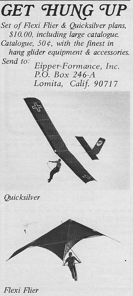
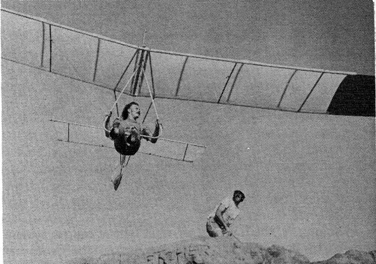
The Quicksilver B, designed by Bob Lovejoy, was available as ready-to-fly, kit form, or as plans. The airframe is aircraft aluminium tubing, wings and tail surfaces are dacron covered. Pitch is weight-shift controlled, while the swingseats connected to the rudder controls turns.
A Quicksilver B kit in 1974 cost $545 and plans sold for $5. Ready to fly the Quicksilver B cost $965. A custom colour wing cost an additional $30.
There were homebuilt versions including one in 1974 with polyethylene covering instead of sail cloth.
Mark Clarkson, flying a Quicksilver in the spring of 1974, flew seventeen miles (measured as a straight line between take-off and landing). The farthest anyone had flown in a hang glider.
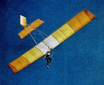
The next Quicksilver improvement was increasing the span (from 30 ft to 32 ft), increasing the chord (from 4 ft to 5 ft), and enlarging the tail (the rudder lost its characteristic “swept” leading edge). The wing also gained square tips (cf the “tapered” tip of the HT/QsA/QsB) to make the Quicksilver C model. This model also had a much reduced camber of the airfoil (the High-Tailer through Quicksilver B model had a “670-15” airfoil, which was made by bending a thin aluminum tube for one-half of it’s length over a 670-15 car tire; it was about 12% camber; the C and later models had about an 8% camber, again, IIRC). This was the same model that Jack Schroeder and Dave Cronk flew in the (much delayed) 1974 Nationals. The C model seemed to be the most prolific of the hang glider models.
Cronk Quicksilver B
All HT and Qs models to this point had a tube for a trailing edge. An experiment was made of moving the trailing edge spar forward, and making a thin trailing edge of fabric only. The leading edge pocket was also made VERY large (maybe about 50% of the chord). Dave Cronk said it ruined the stall characteristics (very sharp and abrupt), but penetration went WAY up. This may have been called a “D” model. Later still the leading edge pocket was made even larger to enclose the leading and trailing edge spars (about 80%) making a double surface airfoil. This model was a rocket in Cronk’s hands, though it appears none were sold to customers.
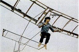
Dave Cronk with a rudder connected to his harness via cords. Pitch is weight shift controlled.
First year motorized 1976.
Hang-glider. L/D: 7-1. Cruise: 18 25 mph. Gross wt: 395 lbs. Empty wt: 155 lbs. Max pilot wt: 220 lbs. Takeoff dist: 40-50 ft. ROC: 250 fpm.
Quicksilver B Wingspan: 30 ft Wing area: 116 sq.ft Weight: 56 lb Cruise speed: 22 mph Max speed: 32 mph Stall speed: 17 mph Max glide ratio: 7-1 Min sink: 250 fpm
Cronk Quicksilver B Wing area: 10.80 m² Wing span: 9.15 m Aspect ratio: 7.75 Hang glider weight: 25 kg Minimum speed: 35 km/h Maximum speed: 50 km/h Max glide ratio (L/H): 7 Minimum sink rate: 1.3 m/s
Single-surface, high wing, open cockpit, 3-axis control with spoilerons and trim tab. Aircraft aluminium with stainless steel wire-braced wing. Tricycle aluminium undercarriage.
Engine: Rotax 503, 54 hp. Prop: Wood 52×34. Wing span: 32 ft. Wing area: 160 ft. Empty wt: 300 lbs. Max wt: 700 lbs. Cruise: 45 mph. Stall: 27 mph. Vmax: 60 mph. ROC: 1000 fpm. TO run: 100 ft. Ldg roll: 200 ft.
Previously called Eipper‑formance, after Dick Eipper, this San Marcos company was renamed Eipper Aircraft in October 1982.
1982: Eipper Aircraft, 1080 Linda Vista Drive, San Marcos, California 92069, USA.
In 1983 the plant moved to larger quarters in Temecula, California, to accommodate increased production, a worldwide dealer network and more than 100 employees.
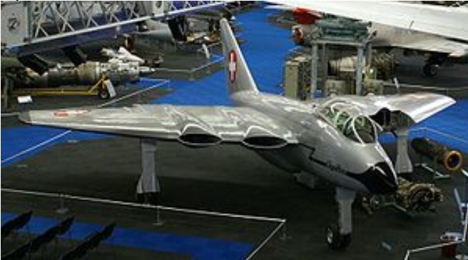
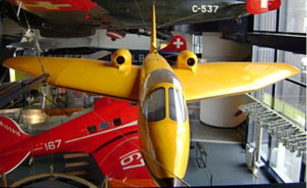
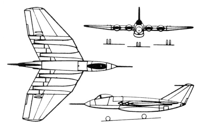
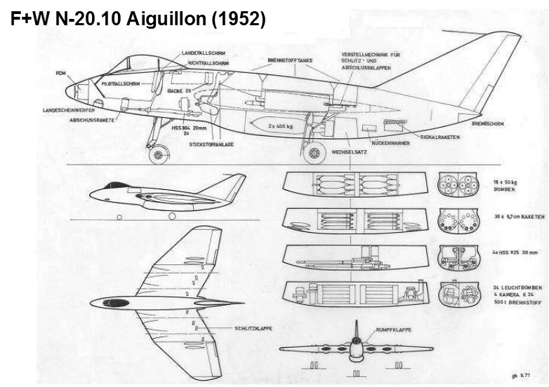
The EFW N-20 “Aiguillon” (English: Stinger) was Switzerland’s first jet fighter aircraft. The Swiss Federal Aircraft Factory developed a design for a four-engined swept winged fighter following the end of the Second World War. The aircraft was to be powered by four turbofan engines buried in the wings, with the bypass air feeding cold-air pipes each side of the engine, being routed through a combustion chamber where additional fuel could be burned as a form of reheat, or deflected though large slots on the upper and lower wings to act as aerodynamic flaps or thrust reversers. Two engines could be shut down in flight to increase range. It was planned that the N-20 would carry its armament in a detachable weapons bay, capable of carrying large loads of cannons, rockets or bombs.
It was initially planned that the aircraft’s engines would be designed and built by the Swiss company Sulzer, but they abandoned this project in 1947, so the British Armstrong Siddeley Mamba turboprop was chosen as the basis for the N-20’s engines, with the propeller reduction gear replaced by a low pressure compressor.
A 3/5 scale wooden glider, the EFW N-20.01 was built to allow testing of novel wing shape, this flying on 17 April 1948. Although the glider was destroyed in a landing accident, it had successfully proven the design, and was followed by a similar sized powered test aircraft, the EFW N-20.02 Arbalète (Crossbow), powered by four 0.98 kN (220 lbf) Turboméca Piméné, mounted above and below the wings, this flying on 16 November 1951. It proved to have good manoeuvrability and reached a maximum speed of 750 km/h (466 mph).
The full scaled aircraft was estimated to have a maximum speed of 1,095 km (680 mph), but the initial converted Mamba, the SM-1, which was test-flown under a de Havilland Mosquito in 1948 and was the first turbofan to fly, did not generate adequate thrust. Considerable further work was required for the definitive two-shaft SM-5 engine, which was meant to generate 14.7 kN (3,300 lbf) thrust. The prototype was completed in 1952 and, fitted with four SM-1 engines, flew briefly during a taxi test on 8 April 1952, but the development of the engine and the N-20 aircraft was cancelled soon afterwards.
N-20 Powerplant: 4 × Armstrong Siddeley Mamba turbofan, 6.2 kN (1,400 lbf) thrust each Length: 12 m (41 ft) Wingspan: 12.60 m (41 ft 4 in) Height: 4 m (12 ft) Wing area: 53 m2 (570 sq ft) Gross weight: 8,709 kg (19,200 lb) Crew: 1
F+W N-20-2 Arbalète Engines: 4 x Turbomèca Piméné jet, 100 kp thrust Length: 7.53 m Span: 7.56 m Height: 2.30 m Wing area: 12.63 m² Empty weight: 1540 Kg MAUW: 1800 Kg Useful load: 190 Kg Max. speed: 720 km/h ROC: 5m / s Ceiling: 8000 m Range: 250 Km
F+W N-20.10 Aiguillon Engines: 4 x Swiss Mamba SM-01 turbofan with plenum chamber burners and thrust reversers, Thrust: 620 kp Length: 12.5 m / 41 ft 0 in Wingspan: 12.6 m / 41 ft 4 in Height: 3.13 m / 10 ft 3 in Wing area: 54.0 sq.m / 581.25 sq ft Max. speed: 1000 km/h / 621 mph T/O weight: 9000 kg Max. speed: 1000 km/h Ceiling: 14000 m
The political ambition of the East German politburo and the cancellation of the Alekseyev 150 Soviet bomber project led to the return to East Germany in 1953 of a group of German engineers and scientists deported to Russia in 1945. They were sponsored to proceed with one of the many commercial designs that they had formulated while in Russia.
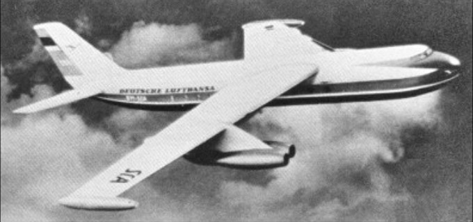
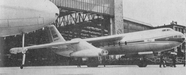
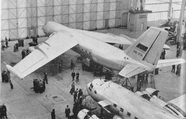
One of these was the 72 seat 152 airliner, which was based on their experience with the Alekseyev 150 and would be powered by a development of the Junkers Jumo turbojet engine named Pirna 014. The design team was led by Brunolf Baade, a former Junkers designer, and the 152 descended from a bomber design started by Junkers during WW2.
The prototype had a glazed nose and an unusual undercarriage arrangement featuring a single central gear assisted by wingtip pod-mounted outriggers, and was completed in May 1958. Late availability of the Pirna engines meant the prototype first flew with Tumansky Rd-9b engines. On its second flight, while rehearsing for the Leipzig trade fair, the prototype 152 crashed due to pressure equalization problems between the multifarious tanks and the inadequate engines. The second heavily modified (152A) model (with modified tanks, conventional undercarriage and a glazed nose) flew twice more before the project was cancelled in 1961 due to national economic crises which were exacerbated by the defection of key design team members.
VEB 152 Engines: 4 x 3165kg VDL Pirna 014A-1 turbojets Max take-off weight: 46500 kg / 102515 lb Wingspan: 25.40 m / 83 ft 4 in Length: 31.30 m / 103 ft 8 in Height: 9.70 m / 32 ft 10 in Max. speed: 920 km/h / 572 mph Range: 2500 km / 1553 miles Crew: 4-5 Passengers: 58