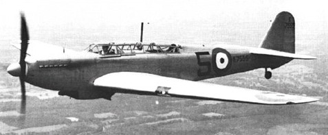
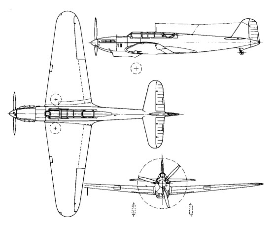
Two prototypes, first flown on 13 June 1937. No production.
Engine; 1 x 1030hp Rolls-Royce Merlin I (later II) Take-off weight; 3989 kg / 8794 lb Empty weight; 2908 kg / 6411 lb Wingspan; 14.43 m / 47 ft 4 in Length; 12.19 m / 39 ft 12 in Height; 4.29 m / 14 ft 1 in Max. Speed; 456 km/h / 283 mph Ceiling; 8108 m / 26600 ft Range; 1481 km / 920 miles Crew; 2
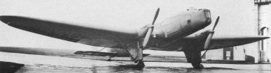
A twin 447kW Rolls-Royce Kestrel Vl-engined cantilever low-wing monoplane heavy night bomber, 14 of which were operated by the RAF from 1937 until just before the outbreak of World War II.
Engines: 2 x Rolls-Royce Kestrel IV, 440kW Max take-off weight; 9072 kg / 20000 lb Empty weight; 5774 kg/ 12730 lb Wingspan; 31.0 m / 101 ft 8 in Length; 18.5 m / 60 ft 8 in Height; 5.6 m / 18 ft 4 in Wing area; 110.0 sq.m / 1184.03 sq ft Max. speed; 249 km/h / 155 mph Cruise speed; 215 km/h / 134 mph Ceiling; 6500 m / 21350 ft Range w/max.fuel; 2200 km / 1367 miles Range w/max.payload; 1900 km / 1181 miles Armament; 3 machine-guns, 1100kg of bombs Crew; 5
Fairey Hendon Mk. II Engines: 2 x Rolls Royce Kestrel VI, 600 hp Length: 60.761 ft / 18.52 m Wing span: 101.739 ft / 31.01 m Max take off weight: 20003.8 lb / 9072.0 kg Max. speed: 135 kts / 250 kph Range: 1180 nm / 2185 km Armament: 3x 7,7mm MG, 753kg Bomb. int.
In 1926 a proposal was made that the RAF should attempt a non-stop flight to India. The chosen vehicle for this attempt was the Hawker Horsley, then entering RAF service as a day and torpedo-bomber. Three unsuccessful attempts were made with the Horsley and the Air Ministry decided to obtain a purpose-built long-range aircraft to make a new attempt. The Fairey Long-Range Monoplane was the result. A clean, high-wing cantilever monoplane of low wing loading, it was of composite construction and fabric-covered. The high-efficiency wing, incorporating a triangulated-tube internal bracing system devised by Hollis Williams, also contained tanks for more than 4,546 litres of fuel. In this aircraft (J9479) Sqd Ldr A. G.Jones-Williams and Flt Lieut N. H. Jenkins flew from Cranwell, Lincolnshire to Karachi, recording the first non-stop flight between Britain and India, but failing to beat the world long-distance record. This aircraft was lost in a second long-range attempt, resulting in the construction of a new aircraft which differed only in detail and by the addition of an autopilot.
In this, during the period 6-8 February 1933, Sqd Ldr Gayford (with Flt Lieut G. E. Nicholetts as navigator) flew non-stop from Cranwell to Walvis Bay, South West Africa, creating a world long-distance record of 8,544km. Only six months later this record was captured by France.
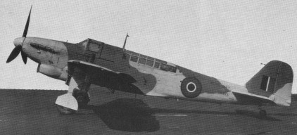
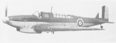
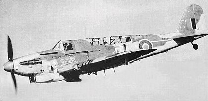
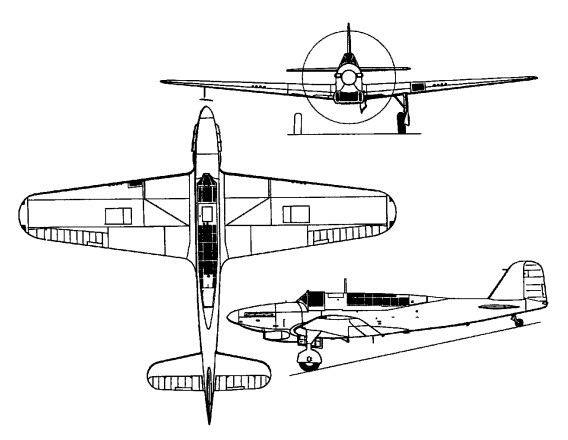
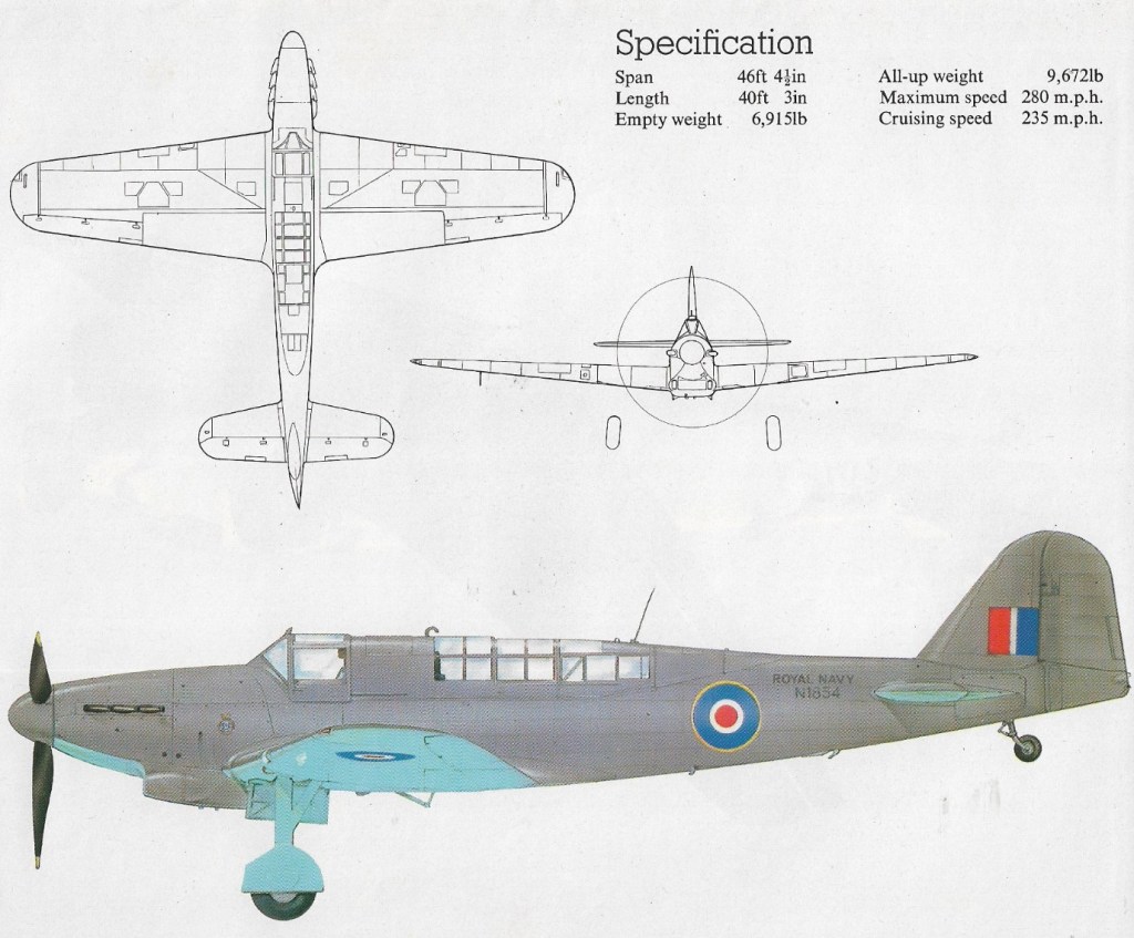
First flown on 4 January 1940, there was no prototype as such for the Fulmar, which was evolved in 1939 from the P.4/34 lightweight development of the Fairey Battle day bomber. The urgent need by the Fleet Air Arm (FAA) for a new fighter led to a rapid trials programme, beginning on January 4, 1940, with the maiden flight of N1854, the first production Fulmar, of which 250 were ordered. The Fulmar I was an all metal cantilever monoplane, with folding wings for carrier stowage; the semimonocoque fuselage housed the deck arrester gear and catapult points, and space was provided for an inflatable dinghy.
The pilot’s cockpit was separated from that of the observer/navigator, and both were enclosed by perspex canopies following the contours of the fuselage. The wide track undercarriage retracted inwards towards the wing roots. The powerplant for all except two early Fulmar 1 aircraft was the 1080 hp Rolls¬Royce Merlin VIII engine. Due to the additional weight of a second crew member, and the special equipment required for carrier operation, the Fulmar did not achieve the same rate of climb or airspeed as its land-based counterparts although this was not necessarily required by the Royal Navy. Armament was very similar to the best in the RAF, consisting of eight 0.303 in (7.7 mm) Browning machine guns four in each wing with twice the ammunition capacity of the Spitfire and Hurricane. The lack of a rear defensive gun was one of the Fulmar’s principal deficiencies, and some crews unofficially fitted an additional gun of their own choice in the rear cockpit.
N1858 – the 5th Fulmar I
Deliveries of the Fulmar I began in June 1940, to 806 Squadron, and it became operational aboard the aircraft carrier Illustrious about two months later. A total of 250 853kW Rolls-Royce Merlin VIII-powered Mk Is were built. At this time, Fairey had plans for the development of the Fulmar II, to be powered by the 1300 hp / 969kW Merlin 30, and with weight reductions brought about by the use of lighter constructional materials. This enabled the Fulmar II to carry the originally intended bombload in the form of a single 113.4 kg (250 1b) or 227 kg (500 1b) bomb beneath the fuselage (the Mk I being limited to eight 9 kg [20 1b] or 11.3 kg [25 1b] bombs under the wings). The Fulmar Mk II with nearly 300 more horsepower, was only 16km/h faster than the Mk I.
Orders for 350 Fulmar IIs were placed during the autumn of 1940, bringing the total number on order to 600. With conversions to Fulmar II beginning on the Mk I production line, the eventual result was that well over 400 were completed as Mk IIs. Ammunition capacity of the Fulmar II was eventually increased from 750 to 1000 rounds per gun but, despite this, the aircraft’s fighting ability was still disappointing. Although short on speed and manoeuvrabil¬ity, it served with 14 FAA squadrons, accounting for more than 100 enemy aircraft until the appearance of more advanced types such as the Seafire and Firefly. During the summer of 1941, four 0.3 in (12.7 mm) machine guns were fitted to one Fulmar. Firing trials proved satisfactory, and the last 100 aircraft were adapted for such an armament, but not all were equipped due to an insufficient supply of the heavier guns. Fulmars were used quite successfully as convoy escorts during the mid war years, and about 100 were converted into makeshift night fighters. In 1943 they were gradually withdrawn from front line service and reassigned to training duties.
Fairey Fulmar Mk.I Engine: 1 x Rolls-Royce Merlin VIII, 805kW / 1065 hp Max take-off weight: 4853 kg / 10699 lb Empty weight: 3955 kg / 8719 lb Wing loading: 31.37 lb/sq.ft / 153.0 kg/sq.m Wingspan: 14.14 m / 46 ft 5 in Length: 12.24 m / 40 ft 2 in Height: 4.27 m / 14 ft 0 in Wing area: 31.77 sq.m / 341.97 sq ft Max. speed: 215 kts / 398 km/h / 247 mph Service ceiling: 6555 m / 21500 ft Endurance: 4 h Armament: 8 x .303in / 7.7mm machine-guns Bombload: eight 9 kg [20 1b] or 11.3 kg [25 1b] bombs Crew: 2
Fairey Fulmar Mk.II Engine: 1 x Rolls-Royce Merlin 30, 1300 hp / 969kW Span: 14.13 m (46 ft 4.5 in) Length: 12.24 m (40ft 2 in) Gross weight: 4695 kg (10350 lb) Maximum speed: 417 km/h (259 mph) Bombload: 113.4 kg (250 1b) or 227 kg (500 1b) bomb
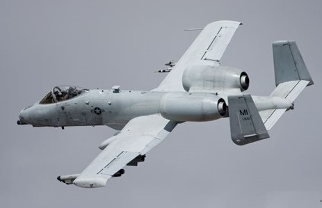
Produced in reply to a specification of 1967, which called for a hard-hitting close-support aircraft, the Fairchild A-10A Thunderbolt II (YA-10A) first flew on 10 May 1972 and was selected by the USAF in preference to the Northrop A-9 on 18 January 1973 after a competitive flyoff, and received a contract for six A-10A aircraft, the first of which flew 15 February 1975. The Thunderbolt’s appearance derives from the care taken to enhance its survival prospects over the battlefield and incorporate maximum fire-power. Absorbing much of the centre fuselage is a GAU-8/A Avenger seven-barrel 30-mm cannon, the muzzle protruding slightly beneath the nose, which can be fired at the rates of 2,100 or 4,200 rounds per minute. The engine location is considered optimum for minimizing hits by ground-fire, and has the additional advantage that the wing and tail mask the infra-red emissions of exhaust gases and therefore affords some protection against heat-seeking SAMs. All of the A-10’s glass is bulletproof and the cockpit itself is surrounded by a heavy tub of titanium. Titanium armor protects both the pilot and critical areas of the flight control system. This titanium “bathtub” can survive direct hits from armor-piercing and high explosive projectiles up to 37 mm in size. The front windscreen can withstand up to a 23 mm projectile. Fire retardant foam protects the fuel cells which are also self sealing in the event of puncture. The airframe has numerous constructional features resistant to battle-damage or conducive to swift repair, such as interchangeable (left or right) flaps, fuselage components, rudders, elevators and main landing gear legs. There are two primary hydraulic systems, each with manual back-up, and the landing gear can be extended under gravity if necessary. Well protected electronically by AN/ALQ-119 jamming pods, plus an AN/ALE-40 chaff and flare dispenser, the Thunderbolt carries a Pave Penny laser designation pod on a pylon to the right of the forward fuselage for accurate marking.
The first production A 10A Thunderbolt II flying on 21 October 1975. Entering service in early 1977, these single seat aircraft are powered by two 9,065 lb thrust General Electric TF34 GE 100 turbofan engines.
Armament comprises a seven barrel, 30 mm gun mounted in the nose, plus a maximum external load of 16,000 lb (7,257 kg) of weapons including air to surface missiles. The General Electric Aircraft Armament Subsystem (30 millimeter Gun System) is located in the forward nose section of the fuselage. The gun system consists of the 30 mm Gatling gun mechanism, double-ended link-less ammunition feed, storage assembly and hydraulic drive system. The General Electric GAU-8/A 30 mm seven barrel cannon, specifically designed for the A-10, provides unmatched tank killing capability. The gun fires armor-piercing projectiles capable of penetrating heavy armor. It also fires a high explosive incendiary round, which is extremely effective against soft skinned targets like trucks. The cannon fires at a rate of 4,200 rounds per minute.
Features of the design are very advanced avionics to enhance operational capability and provision of titanium 737 mph armour for the entire cockpit area.
Avionics equipment includes communications, inertial navigation systems, computer-aided fire control and weapons delivery systems, electronic countermeasures, target penetration aids and self-protection systems. The A-10 employs both electronic and infrared countermeasures against enemy weapons systems. The weapons delivery system incorporates a heads-up display that provides the pilot with references for flight control and weapons employment. The weapons delivery systems include head-up displays that indicate airspeed, altitude and dive angle on the windscreen, a low altitude safety and targeting enhancement system (LASTE) which provides constantly computing impact point freefall ordnance delivery; and Pave Penny laser-tracking pods under the fuselage.
Development of a night/adverse weather (N/AW) two seat version has been initiated, the prototype first flying in 1979. This is intended to allow the pilot to concentrate on control of the aircraft under night or adverse weather conditions, the second seat occupied by a weapons system officer to handle the electronics. The private-venture Thunderbolt N/AW (Night/Adverse Weather) was offered without success.
The A-10/OA-10 have excellent maneuverability at low air speeds and altitude, and are highly accurate weapons-delivery platforms. The A-10 has half the turning radius of the US Air Force’s other primary CAS aircraft, the F-16. After initially leaving a target, the A-10 can turn around and hit the same target again, all in around 7 seconds. Due to its large combat radius, the Thunderbolt II can loiter for extended periods of time, allowing for the coordination required to employ within yards of friendly forces. They can operate under 1,000-foot ceilings (300 meters) with 1.5-mile (2.4 kilometers) visibility. Using night vision goggles, A-10/ OA-10 pilots can conduct their missions during darkness.
The A-10 is capable of sustaining operations on unimproved airfields and the A-10’s rapid re-fueling and re-arming capability allows it to operate from forward bases close to the front lines. It is also capable of refueling in the air.
Altogether the USAF has received 713 aircraft, including A-10B dual control-trainers. Modelled on the A-10N/AW evaluator, the A-10B was in production featuring a second cockpit and taller fins.
The USAFs 33rd Tactical Fighter Training Squadron at Davis-Monthan AFB, Arizona, received its first Fairchild A 10A Thunderbolt IIs in February 1976.
The first combat-ready A-10A wing was the 345th Tactical Fighter Wing, based at Myrtle Beach, South Carolina, to which deliveries began on 20 March 1977. The last of 713 A-10s was handed over to the USAF on 20 March 1984. This was the end of aircraft manufacturing in Hagerstown and Washington County. A-10s were fitted with AIM-9L Sidewinder AAM dual rail adaptors, to allow four missiles to be carried in pairs.
The primary mission of the OA-10 is to act as forward air controller to coordinate and direct friendly air forces in support of land forces. Northrop Grumman acquired the A-10 programme from Fairchild in 1987. In 2000 preparations for the Precision Engagement Program (PEP) upgrade program began. PEP gives the A-10 the capability of deploying precision-guided weapons. The upgrade is carried out in two phases, called Spiral One and Spiral Two. The aircraft is designated A-10C. Between July and October 2004 the first A-10C underwent ground and instrumentation tests prior to the first flight in November 2004. In total 13 A-10C aircraft were for flight testing. The entire A-10A fleet is expected to receive the PEP upgrade. The last aircraft due to be modified before the summer of 2009.
Fairchild A-10A Thunderbolt II Engine: 2 x General Electric TF34-GE 100 turbofan, 9065 lb / 4112-kg Wingspan: 57 ft 6 in / 17.53 m Length: 53 ft 4 in / 16.25 m Height: 4.47m / 14 ft 8 in Wing area: 47 sq.m / 506.0 sq ft Empty equipped weight: 11,321 kg / 24,959 lb MTOW: 50,000 lb / 22,680 kg Wing load : 96.97 lb/sq.ft / 473.0 kg/sq.m Max speed: 439 mph / 706 kph Combat limit: 704 km/h (438 mph) at 1525 m (5,000 ft) Service ceiling 13,636m / 45,000 ft Initial ROC: 1830 m / min / 6,000 fpm Ferry range: 2454 sm / 3949 km Combat radius: 930+ km T/O run (to 15m): 780 m Ldg run (from 15m): 715 m Armament: 1 x 30 mm GAU-8/A Avenger seven-barrel cannon (1174 rds) Pylons: 11 up to 7,258 kg / 16,000 lb Fuel internal: 6225 lt. Air refuel: Yes. Seats: 1
The original Fokker F-27 Friendship was built in Holland. Fairchild has built the F-27 under license from Fokker since 1958. The first F-27 models had a maximum gross weight of 40,500 pounds and seated 44 passengers. Power was supplied by twin 1,720 shp Dart turboprops. When Fairchild merged with Hiller Aircraft, the designation of the airplane was changed to FH-227 and the fuselage was stretched by six feet, giving increased cabin space for passengers and freight. The stretched airliner will accommodate up to 52 passengers. In 1960, power was increased to 2,105 shp. The stretched version was fitted with 2,250 shp engines, and ultimately the FH-227 received a redesigned windshield, stronger landing gear, strengthened rear fuselage, heavier wing skin, propellers of increased diameter and a more powerful 2,300 shp Dart turboprop. Fairchild discontinued building the FH-227 under license from Fokker in 1975.
Engines; 2 x Rolls-Royce RDa-7 Dart Mk.532, 1655kW / 2,300 shp Wingspan; 29.0 m / 95 ft 2 in Length; 25.5 m / 83 ft 8 in Height; 8.4 m / 27 ft 7 in Wing area; 70.0 sq.m / 753.47 sq ft Take-off weight; 20640 kg / 45504 lb Empty weight; 12478 kg / 27509 lb Fuel capacity: 1,364 lb Max. Speed; 483 km/h / 300 mph Top cruise: 270 mph Stall speed: 87 mph Initial climb rate: 1,560 fpm Service ceiling: 28,000 ft Takeoff run: 3,950 ft Landing roll: 4,100 ft Range w/max.fuel; 2500 km / 1553 miles Range w/max.payload; 800 km / 497 miles Seats: 44-52 Crew; 2-3
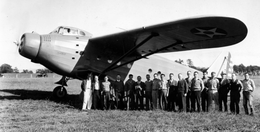
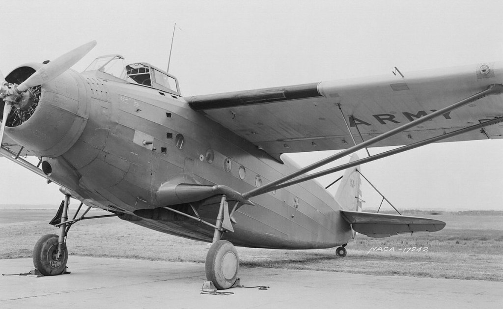
The Kreider-Reisner XC-31 or Fairchild XC-31 was an American single-engined monoplane transport aircraft of the 1930s designed and built by Kreider-Reisner. It was one of the last fabric-covered aircraft tested by the U.S. Army Air Corps.
Kreider-Reisner XC-31 – 34-026
The XC-31 was built with an aluminum alloy framework covered by fabric, and featured strut-braced wing and fully retractable landing gear, with the main gear units mounted on small wing-like stubs and retracting inwards. An additional novel feature was the provision of main cargo doors that were parallel with the ground to facilitate loading.
Designed as an alternative to the emerging twin-engined transports of the time such as the Douglas DC-2, it was evaluated by the Air Corps at Wright Field, Ohio, under the test designation XC-941, but rejected in favor of all-metal twin-engined designs.
XC-31 at Langley
Following evaluation by the USAAC, the XC-31 was transferred to NACA, which used it for icing studies at its Langley Research Center.
Powerplant: 1 × Wright R-1820-25, 750 hp (559 kW) Wingspan: 75 ft 0 in (22.86 m) Wing area: 802 sq ft (74.5 m2) Length: 55 ft 5 in (16.89 m) Height: 15 ft 10 in (4.83 m) Empty weight: 7,322 lb (3,321 kg) Gross weight: 12,750 lb (5,783 kg) Maximum speed: 154 mph (248 km/h, 134 kn) Cruise speed: 143 mph (230 km/h, 124 kn) Range: 775 mi (1,247 km, 673 nmi) Service ceiling: 15,000 ft (4,570 m) Crew: 1 (Pilot) Capacity: 15 passengers or 3,500 pounds (1,600 kg) of cargo
During 1934 the Fairchild company designed a business or executive aircraft with five seats, designated the Model 45. It first flew on 31 May 1935. The Model 45 was a low-wing cantilever monoplane with a conventional cantilever tail unit and a retractable tailwheel landing gear. The aircraft was powered by a 225 hp (168 kW) Jacobs L-4 radial engine and had a luxury five-seat interior as standard. Flight testing showed that the aircraft performed well, although it was described as sedate.
The company predicted that the Model 45 would have only limited market appeal in that form, therefore only the prototype was built.
Fairchild then upgraded the prototype with a larger engine, the Wright R-760 radial, for evaluation. In this configuration it was designated the Model 45-A. This configuration was placed in production, with about 16 units being completed.
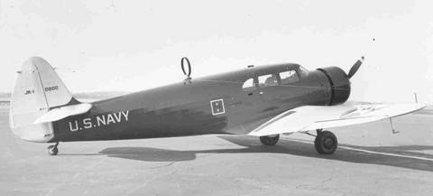
One aircraft was bought as an executive transport by the United States Navy as the JK-1. After the United States entered the Second World War, two aircraft were impressed into service with the United States Army Air Forces as the UC-88.
Fairchild JK-1
In 1997, Greg Herrick requested drawings of a Fairchild 45 tail section for an ongoing restoration project. The request was refused, citing the design was a trade secret. This led to a FOIA request, and lawsuit that was debated in the United States Supreme Court. The effort led to the “Herrick amendment” added to the FAA Air Transportation Modernization and Safety Improvement Act of 2012. The amendment released the ATC type certificate information for 1,257 aircraft first certified in 1927 through the beginning of World War II in 1939.
Variants:
45 One prototype Engine: 225 hp (168 kW) Jacobs L-4
45-A Production aircraft 16 built Engine: 320 hp (239 kW) Wright R-760 Wingspan: 39 ft 6 in (12.04 m) Wing area: 248 sq ft (23.04 m2) Length: 30 ft 1 in (9.17 m) Height: 8 ft 2 in (2.49 m) Empty weight: 2,512 lb (1,139 kg) Gross weight: 4,000 lb (1,814 kg) Maximum speed: 170 mph (274 km/h, 150 kn) Range: 650 mi (1,046 km, 560 nmi) Service ceiling: 18,700 ft (5,700 m) Crew: one Capacity: four passengers
JK-1 One 45-A for the United States Navy
UC-88 Two 45-As impressed into service with the United States Army Air Forces
The Fairchild Model 41 Foursome was a light aircraft developed in the United States in the late 1920s and produced as the Model 42 Foursome. It was a conventional high-wing, strut-braced monoplane with fixed tailwheel undercarriage. The pilot and three passengers were seated within a fully enclosed cabin, and the aircraft generally resembled a scaled-down version of Fairchild’s successful FC-2 design.
Fairchild 41
Two prototypes were built as the Model 41 and Model 41A leading to the Model 42 production version which was built in a small series. This production version differed from the prototypes in having a redesigned, strut-braced empennage in place of the wire-braced unit of the earlier aircraft, and a more powerful version of the Wright Whirlwind powerplant.
Variants:
Model 41 Foursome First prototype, one built Engine: 220 hp (160 kW) Wright J-5 Seats: 4
Model 41A Foursome Second prototype, one built Engine: 300 hp (220 kW) Wright J-5 Seats: 4
Model 42 Foursome Production, six built and two converted from the 41 and 41A. Engine: 330 hp (250 kW) Wright J-6 Wingspan: 45 ft 6 in (13.86 m) Length: 30 ft 6 in (9.30 m) Maximum speed: 130 mph (210 km/h, 110 kn) Range: 700 mi (1,130 km, 610 nmi) Seats: 4
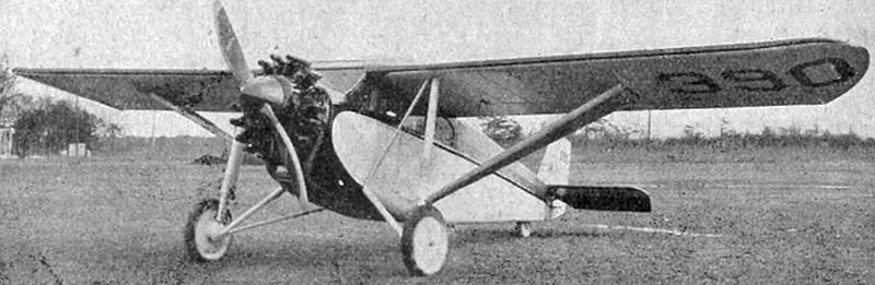
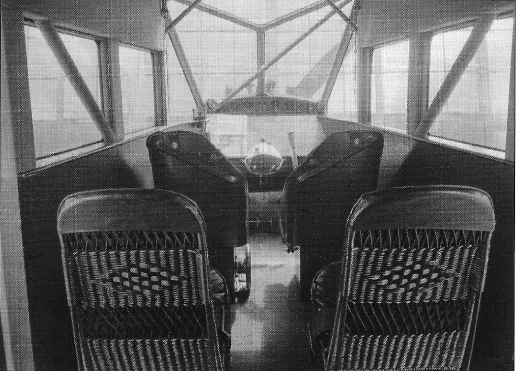
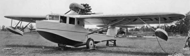
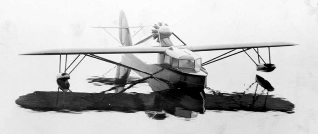
The Fairchild FB-3 (Flying Boat number 3) was an all-metal flying boat designed by Arthur Stelb and developed by the new Fairchild Metal Boat Division of the Fairchild Aircraft Corporation. The prototype was built at Fairchild’s Farmingdale, Long Island facility. The FB-3 was an amphibious high-wing strut-braced monoplane with retractable landing gear, powered by a high pylon mounted pusher configuration radial engine. The two-step hull provided floatation with two outboard floats for stability. The wings used metal spars and ribs with fabric covering. The interior was well finished for its time.
The prototype aircraft (NX7385) was test flown in 1929 but did go into production.
Fairchild FB-3 Engine: 1 × Pratt & Whitney Wasp R-1340, 420 hp (310 kW) Wingspan: 52 ft (16 m) Length: 41 ft (12 m) Maximum speed: 113 kn; 209 km/h (130 mph) Cruise speed: 100 kn; 185 km/h (115 mph) Seats: 4