Financed by the Royal Aeronautical Society, the Weybridge Man Powered Aircraft Group’s Dumbo, which took 10,000 man hours to build and had wings which spanned 36.6 m (120 ft) and drooped down at rest. It has a structure of metal tube covered in see-through ‘Melinex’. All the flying surfaces are capable of being warped to act as control surfaces.
The aircraft has a bullet-shaped fuselage with a four-unit tailplane mounted at the extreme ear with a pusher propeller behind that. The pilot sits in the nose.
The wing is internally braced and set low on the fuselage.
Paul Westphal built his second design “Taube” after the guidelines of the army. It passed the tests easily, but was not bought. He then gave up his own attempts.
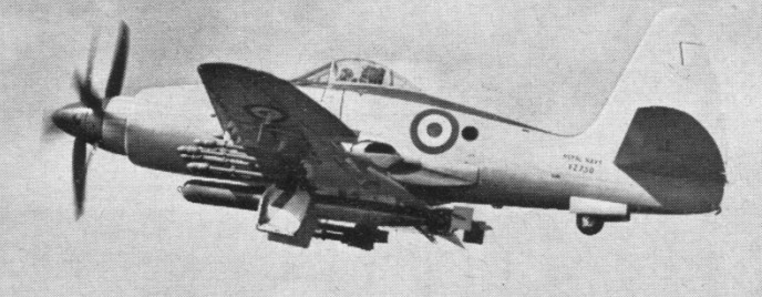
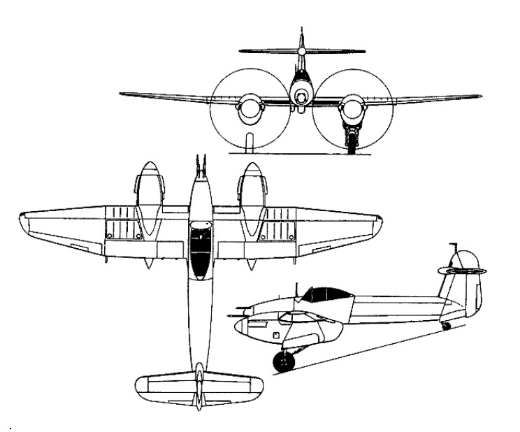
Under the project designation P.10, Westland began to study early in 1944 a long-range shipboard day fighter for Naval use, with the added capability of carrying a torpedo, rockets or bombs for anti-shipping strikes. Around this proposal, Specification N. 11/44 was written, and, in November 1944, a contract was confirmed for six prototypes (including two in land-based RAF configuration to Spec F.13/44). Redesignated W.34, and subsequently named the Wyvern TF Mk 1, the Westland aircraft was a low-wing monoplane of relatively conventional layout, but larger and heavier than any previous British single-seat Naval fighter. It had upward-folding outer wing panels with hinged tips, and a 3500hp Rolls-Royce Eagle 24-cylinder liquid-cooled H-type engine driving eight-blade contraprops. Provision was made in the design for the later introduction of a turboprop engine, such as the Rolls-Royce Clyde. Basic armament comprised four 20-mm Hispano Mk V cannon in the wings, with the possibility of carrying a 46cm Mk VIII torpedo under the fuselage three 464kg bombs or eight 27kg rocket projectiles.
Westland Wyvern TF1, pre production aircraft
Only 15 aircraft were built with the Rolls Royce Eagle (2700 hp) fitted.
Westland Wyvern TF1, pre production aircraft
In August 1946, an order for 20 pre-series Wyverns with Eagle engines was confirmed, but a planned batch of 10 for the RAF was dropped, together with the F.13/44 prototypes. Subsequently, the pre-production batch was halved.
The first of six prototypes flew on 16 December 1946. However, a turboprop version with the Armstrong Siddeley Python had meanwhile been given the go-ahead and the Wyvern TF Mk 1s were assigned to various development tasks, never becoming operational. All six prototypes were flown, as were six pre-series TF Mk 1s, but the final four of the latter, although built, remained unflown as all development effort switched to the TF Mk 2.
Following the RAF’s decision to pro¬ceed no further with this project the Royal Navy opted to concentrate all future development around the Arm¬strong Siddeley Python turboprop en¬gine.
The Naval Air Staff ordered three prototypes of the (W.35) Wyvern TF Mk 2, to Specification N.12/45. Two were to be powered by the Armstrong Siddeley Python and the third by a 4500hp Rolls-Royce Clyde. In the event, the former engine was to be preferred for production aircraft. In overall configuration and armament the Wyvern TF Mk 2 closely resembled the Mk 1, although there were differences in detail, and the first flight of the Clyde-engined prototype was made on 18 January 1949, followed by the first with a Python on 22 March 1949.
Flight testing soon showed the need for modifications, noticeably to the tail unit with the progressive introduction of a larger tailplane, more fin area, dihedral on the tailplane and, eventually, finlets. Prolonged testing and development also proved necessary to achieve a satisfactory engine/propeller/throttle response system for the special demands of carrier landings, involving the two Python prototypes and most of 20 pre-series TF Mk 2s ordered in 1948 (together with a single W.38 Wyvern T Mk 3 two-seat training version).
The first pre-series TF Mk 2, with a Python 2, flew on 16 February 1950, and, in June that year, became the first British turboprop aircraft to engage in carrier deck landings, aboard HMS Illustrious. Carrying a belly torpedo and 16 RPs it was a single seat strike/intruder fighter.
The final seven pre-series aircraft were completed as Wyvern S Mk 4s, this being the designation of the definitive variant with all the handling and engine modifications, and the primary mission changed to strike. The S Mk 4 was powered by a Python 3 rated at 3670hp plus 535kg residual thrust.
The principal production model was the Wyvern S.Mk 4, 94 being built in the early to mid-1950s, and these were augmented by a number of Wyvern TFMk 2 aircraft modified to Wyvern S.Mk 4 standard. Deliveries to the first FAA squadron (No 813) began during 1953. In addition, a solitary Wyvern T.Mk. 3 trainer was also completed although no production orders were forthcoming.
Westland Wyvern S.4
In September 1954, 813 embarked with their Wyverns on HMS Albion for carrier-based service in the Mediterranean. The Wyvern soon showed a worrying habit for flameout on catapult launch; the high G forces resulting in fuel starvation. A number of aircraft were lost off Albion’s bows and Lt. B. D. Macfarlane made history when he successfully ejected from under water after his aircraft had ditched on launch and been cut in two by the carrier. 813 did not return to Albion until March 1955 when the problems had been resolved.
830 Squadron was re-equipped with new aircraft before embarking in HMS Eagle on April 19, 1956. These aircraft were still designated Wyvern S.Mk4 and differed slightly in external appearance. The modifications which were visible from external inspection were: (i) A modified cockpit canopy. This was the same shape as the previous canopy but it was a completely clear hood and did not have the metal bracing strut just aft of the pilot’s head. (ii) The airbrake was re-designed and this can be seen from an underside view of the aircraft. (iii) The folding wingtip facility was modded out.
Three other squadrons subsequently flew the Wyvern S Mk 4, front-line service continuing until March 1958. Operational use of the Wyvern during the Suez campaign in 1956 marked the only occasion on which British turboprop-powered aircraft saw combat use.
830 Squadron aircraft were flown ashore to Stretton and to Lee-on-Solent on January 3, 1957, and the squadron was officially disbanded from HMS Eagle in Devonport dockyard on January 5 1957.
Wyvern TF Mk 1 Max take-off weight: 9924 kg / 21879 lb Empty weight: 7005 kg / 15443 lb Wingspan: 13.42 m / 44 ft 0 in Length: 11.96 m / 39 ft 3 in Height: 4.72 m / 16 ft 6 in Wing area: 32.98 sq.m / 354.99 sq ft Max. speed: 734 km/h / 456 mph Ceiling: 9785 m / 32100 ft Range: 1908 km / 1186 miles
Wyvern S.Mk 4 Engine: one 4,110-eshp (3065-ekW) Armstrong Siddeley Python ASP3 turboprop Maximum speed 616 km/h (383 mph) at sea level Service ceiling 8535 m (28,000 ft) Range 1455 km (904 miles) with auxiliary fuel Weight empty 7080 kg (15,608 lb) MTOW 11113 kg (24,500 lb) Wing span 13,41 m (44 ft 0 in) Length 12.88 m (42 ft 3 in) Height 4.80 (15 ft9 in) Wing area 32.98 sq.m (355 sq ft) Armament: four 20-mm cannon Bombload: 1361 kg (3,000 lb)
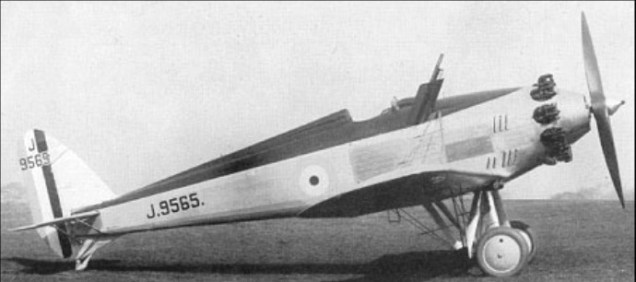
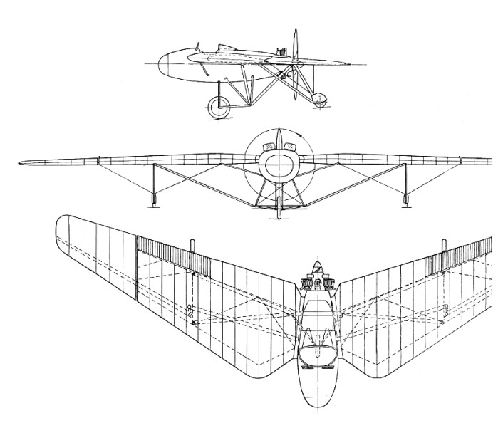
Usually known as the COW-Gun Fighter, this prototype monoplane was one of two ordered by the Air Ministry (with the unorthodox Vickers Type 161) in fulfilment of Specification F.29/27. This called for an aircraft armed with the 37mm Coventry Ordnance Works (COW) cannon that had been evolved during World War I and was thought to have potential as an anti-bomber weapon. The COW gun was to be mounted at an upward angle of at least 45 degrees from the horizontal, with the idea that the fighter would approach enemy bombers from below and astern. The Westland prototype was, in effect, an enlargement of the F.20/27 prototype, and had the COW gun mounted to fire upwards at 55 degrees, with the breech casing in the starboard side of the open cockpit. Aiming was by means of a periscopic sight, and a special “ammunition dispenser” carried 39 rounds. The fighter was of similar all-metal construction to the F.20/27 and, like the latter, was first flown with a small fin and rudder which later had to be considerably enlarged to obtain satisfactory spinning characteristics. Powered by a 485hp Bristol Mercury IIIA nine-cylinder air-cooled radial, the F.29/27 first flew in December 1930, but the RAF quickly lost interest in the COW gun. With a Mercury IVA, the COW-Gun Fighter remained at the A & AEE until July 1934.
Max take-off weight: 1762 kg / 3885 lb Empty weight: 1186 kg / 2615 lb Wingspan: 12.45 m / 41 ft 10 in Length: 9.09 m / 30 ft 10 in Height: 3.22 m / 11 ft 7 in Wing area: 20.62 sq.m / 221.95 sq ft Max. speed: 296 km/h / 184 mph Ceiling: 8900 m / 29200 ft
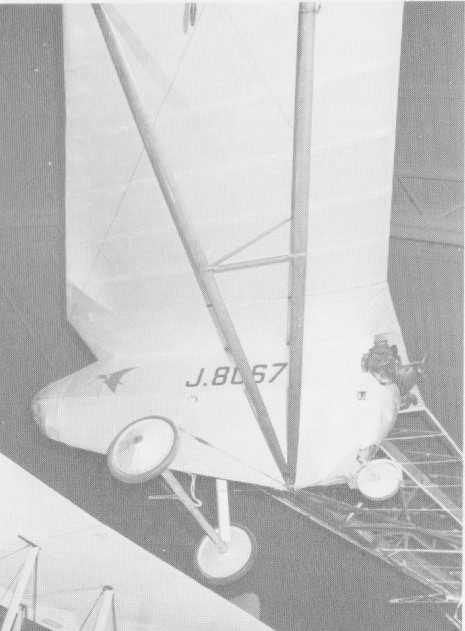
In the early 1920’s Captain (now Professor) G. T. R. Hill began a study of aeroplane design, with the object of discovering a means of securing safety in flight. This was to be achieved by improving stability and control at low speeds, and even below stalling speed, so that the fatal spin, all too common in those days, would never occur. Captain Hill’s investigations eventually led him to evolve a tailless form of aircraft in which the wings were arranged roughly in the form of a blunt arrow-head and, it was built in his home with Mrs. Hill’s assistance, he built a prototype as a glider, naming it after that pre-historic reptile the Pterodactyl, in view of its wing-tip control.
Successful tests on the South Downs demonstrated to the Air Ministry the practicability of the design, and they, in view of its possible military advantages, co-operated with Captain Hill to fit the machine with a small 34hp Bristol Cherub engine.
The first power flight of the Pterodactyl took place at the Royal Aircraft Establishment, Farnborough in December 1925, and, after final demonstrations before Sir Samuel Hoare, then Secretary of State for Air, the Westland Works took over the development of the type, Captain Hill joining the staff for this purpose.
Hill Pterodactyl I J8067
The Pterodactyl I was flown until superseded by the IA in 1928 and was subsequently stored by Prof Hill. He presented the machine to the Science Museum in 1951.
The first Westland-Hill production was a side-by-side two-seater J9251, with wings differing in plan-form considerably from those of the original machine. It was designated the Mk. IA when fitted with a 34hp Bristol Cherub engine and first flown in 1928.
After the Cherub engine was replaced by a 70hp Armstrong Siddeley Genet, and small rudders were fitted, it was given the mark number IB.
With a re-designed undercarriage it was re-designated IC.
The design was important, since it successfully demonstrated that a wing loading far greater than that of the prototype did not affect the solutions of stability and control evolved by Captain Hill. Originally flown by Flt.-Lt. L. G. Paget, A.F.C., and with Flt.-Lt. F. J. Brunton carrying out some of the later work, this Pterodactyl was used for a great number of investigations and, as a result, it was possible to proceed with complete confidence to other designs, of which the Pterodactyl Mk. IV was the next to be built. The Pterodactyl IV K1947 of 1931 was a three seat, larger version powered by a 120-hp Gipsy III.
Hill and Westland had plans for a whole series of the Pterodactyls, includ¬ing a flying boat and an airliner, but only four were built, the last being the Pterodactyl Mark V which had a 600 hp Rolls-Royce Goshawk steam cooled engine and was intended as a fighter. The theory was that the tailless configuration would give the rear gunner an almost unlimited field of fire with his pair of synchronized Vickers guns.
Test pilot Harald Penrose was soon demonstrating the Pterodactyl’s stability, and even performing aerobatics as well as flying it inverted. But a landing accident damaged the sole Mark V and further work on Hill’s designs was abandoned in the mid 1930s.
Hill I Wingspan: 13.72 m / 45 ft 0 in Wing area: 20.62 sq.m / 233 sq.ft Empty weight: 207.7 kg / 458 b
Mk. IA Engine: 1 x 32hp Bristol Cherub Wingspan: 13.86 m / 45 ft 6 in Wing area: 18.58 sq.m / 199.99 sq ft Length: 5.18 m / 17 ft 0 in Height: 2.03 m / 7 ft 8 in Max take-off weight: 408 kg / 899 lb Speed: 70 mph
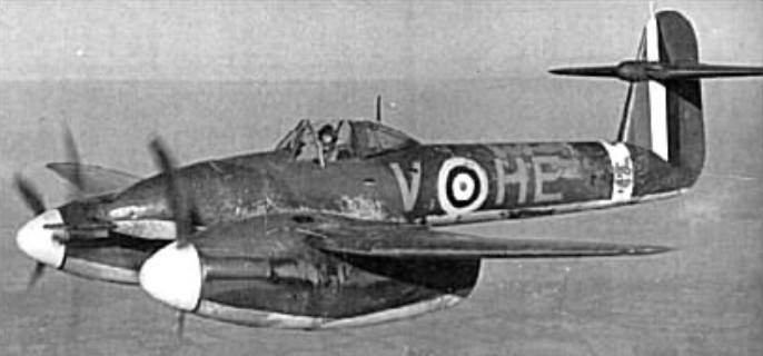
The only Westland fighter to achieve operational status with the RAF, the Whirlwind was designed in response to Specification F.37/35 for a “cannon fighter” armed with four 20mm guns. As the P.9, the Westland design emerged as a low-wing monoplane with two Rolls-Royce Peregrine I 12-cylinder liquid-cooled Vee engines, each rated at 885hp at 4575m. The four Hispano Mk I guns were grouped in the nose, the pilot enjoyed a good all-round view from a fully-enclosed cockpit in line with the wing trailing edge, and radiators were buried in the wing leading edges inboard of the nacelles. Construction was of metal throughout, with flush-riveted stressed skins, a novelty being the use of magnesium rather than aluminium sheet to cover the monocoque fuselage aft of the cockpit.
Two prototypes were ordered by the Air Ministry in February 1937, and the first of these flew on 11 October 1938. Despite delays in development and production of the Peregrine engine, two contracts were placed in 1939, each for 200 fighters as Whirlwind Is, and the first series aircraft (P6966) flew in June 1940.
In the event, production ended with 114 aircraft built, these serving with only two RAF squadrons (Nos 263 and 137). Armament problems and changing operational needs curtailed the usefulness of the Whirlwind, which was enhanced in late 1942 by the addition of a pair of wing racks to carry two 113kg or 227kg bombs. Operational use of the Westland fighter came to an end in November 1943.
Whirlwind I Engines: 2 x Rolls Royce Peregrine I, 873 hp Wingspan: 13.72 m / 45 ft 0 in Wing area: 23.22 sq.m / 249.94 sq ft Length: 9.83 m / 32 ft 3 in Height: 3.20 m / 11 ft 6 in Empty weight: 3699 kg / 7840 lb Max take-off weight: 4658 kg / 10,270 lb Max. speed: 313 kts / 579 km/h / 360 mph Landing speed: 80 mph ROC: 3000 fpm / 915 m/min Ceiling: 9150 m / 30000 ft Range: 1287 km / 800 miles Crew: 1 Armament: 4x 20mm Hispano Mk.1 MG, 60 rds each
Whirlwind IA Engines: 2 x Rolls Royce Peregrine I, 873 hp Wingspan: 13.72 m / 45 ft 0 in Wing area: 23.22 sq.m / 249.94 sq ft Length: 9.83 m / 32 ft 3 in Height: 3.20 m / 11 ft 6 in Max take-off weight: 5165 kg / 11387 lb Empty weight: 3770 kg / 8311 lb Max. speed: 313 kts / 579 km/h / 360 mph Landing speed: 80 mph Ceiling: 9150 m / 30000 ft Range: 1287 km / 800 miles Crew: 1 Armament: 4x 20mm MG Bombload: 454kg
In 1934, the British Air Ministry issued Specification A.39/34 for an army co-operation aircraft to replace the Hawker Hector. Initially, Hawker Aircraft, Avro and Bristol were invited to submit designs, but after some debate within the Ministry, a submission from Westland was invited as well. The Westland design, internally designated P.8, was the work of Arthur Davenport under the direction of W.E.W. (Teddy) Petter. It was Petter’s second aircraft design and he spent considerable time interviewing Royal Air Force pilots to find out what they wanted from such an aircraft. There was no clear idea of what the new aircraft needed to be able to do, and so in 1935 Petter spent some time with the army co-operation squadrons. Even there he found no consensus, but most pilots agreed that the most important requirements for the new aircraft were to be able to operate from small spaces, be able to fly at low speeds without stalling or losing control and that the pilot needed a clear forward view.
Davenport and Petter worked to design an aircraft around these features: the result was unconventional and looked, by its 15 June 1936 maiden flight, rather antiquated. However, it was also the first custom-designed army cooperation aircraft to be built for the RAF since the Armstrong Whitworth Atlas of the late 1920s.
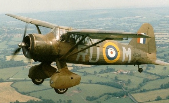
With a distinctive high-set wing and small stub-wings attached to the main wheel struts to carry weapons/stores, despite its appearance, the Lysander was aerodynamically advanced with automatic wing slats, slotted flaps and a variable incidence tailplane. These refinements gave the Lysander a very low stalling speed. One of the original STOL (Short Take Off and Landing) designs, the Lysander could land and take off in the length of a football field.
The Lysander was a two seater, powered by a Bristol Mercury air-cooled radial engine, metal structured with top mounted wings and a fixed undercarriage inside large, streamlined spats. The wings had an unusual reverse taper towards the root, which gave the impression of a gull wing, although in fact the spars were perfectly straight. The wings were supported by V struts that linked to the undercarriage and had a girder type construction with a light wood frame around that to give the aerodynamic shape. The forward part was duralumin tube joined with brackets and plates, and the after part welded stainless steel tubes. Plates and brackets were cut from channel extrusions rather than forming from sheet steel. The front spar and lift struts were extrusions. The wing itself was fabric covered. The wheels were contained within streamlined spats, which also contained the forward firing guns. The spats also had mountings for small, removable stub wings that could be used to carry light bombs or supply canisters. Twelve small antipersonnel bombs could be carried under small stub-wings fitted to the spats.
Armament consisted of one 0.303 in Browning machine gun operated by the pilot, in each wheel spat, firing outside the propeller disc, and a free Browning in the rear cockpit.
Despite its appearance, the Lysander was aerodynamically advanced; it was equipped with automatic wing slats, slotted flaps and a variable incidence tailplane. These refinements gave the Lysander a stalling speed of only 65 mph (104 km/h, 56.5 knots). It also featured the largest Elektron alloy extrusion made at the time: a single piece inside the spats supporting the wheels. The Air Ministry requested two prototypes of the P.8.
The first prototype made its first taxiing test on 10 June 1936 and the first of two prototypes was flown initially on 15 June 1936 at Boscombe Down. The Air Ministry preferred the Lysander to the competing Bristol Type 148, quickly selecting the Westland aircraft for production, issuing a contract in September 1936. On 11 December 1936 Westland received a first order for 169 Lysanders. The first production aircraft appeared in March 1938, and were delivered to No. 16 squadron, at Old Sarum. This base was also the home of the School of Army Cooperation, another early recipient of the aircraft. Early aircraft were also sent to No. 5 Squadron in India for tropical trials. Like other British army air co-operation aircraft, it was given the name of a military leader; in this case, the Spartan General, Lysander.
The type began to enter service with No. 16 Squadron RAF in June 1938, and they were the first British aircraft to be based in France at the beginning of World War II and the last to see action in France during the evacuation from Dunkirk. Four Lysander squadrons moved to France during the phoney war period (Nos. 2, 4, 13 and 26). When the Germans attacked in May 1940, their armies were supported by swarms of Bf 109s. Allied fighters were overwhelmed. While the Fairey Battle was the most famous victim of this period, the four Lysander squadrons suffered very nearly as badly. Of 174 Lysanders sent to France, 88 were lost in aerial combat and 30 were destroyed on the ground. 120 crewmen were lost. Only 50 aircraft survived to return to Britain.
After the withdrawal from France Lysanders patrolled the coastal areas of south and east England at dawn and dusk as an anti-invasion reconnaissance measure. It was planned that in the event of an invasion the Lysanders would bomb and machine gun German troops on the beaches.
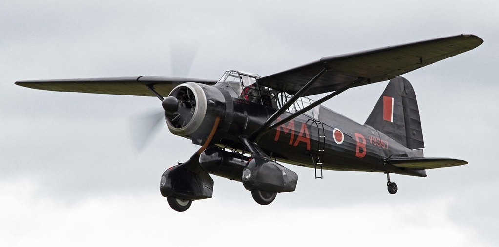
The majority of Lysander squadrons were actually formed after the fall of France, performing vital air-sea rescue duties. Its low speed allowed it to drop dinghies and supplies close to downed aircrew. The Lysander was also used for radar calibration and as target tugs. Of the (probably) 1,670 aircraft built, some 964 were Mk III aircraft, which first appeared in August 1940. The Lysander is most famous for its work with the Special Operations Executive. Two squadrons were formed to support the SOE, first No. 138 (Special Duties) squadron in August 1941 and then No. 161 (SD) squadron. These squadrons were given a mix of aircraft, including Hudsons, Whitleys and Halifaxes as well as the Lysander. The larger aircraft were used for parachute drops, either of agents or supplies. The aircraft’s exceptional short-field performance made possible clandestine missions behind enemy lines that placed or recovered agents, particularly in occupied France. For this role, the Mk IIIs were fitted with a fixed entry/exit ladder over the port side to hasten access to the rear cockpit and a large drop tank under the belly. In order to slip in unobtrusively, the Lysanders were painted matt black, and operations were often planned for moonless nights. Flying without any navigation equipment other than a map and compass, Lysanders would land on short strips of land, such as fields, marked out by four or five torches. They were only designed to carry one passenger in the rear cockpit, but in case of urgent necessity, two could be carried in extreme discomfort. The Lysander proved to be a success in this role and continued to undertake such duties until the liberation of France. Between August 1941, when No. 138 squadron began Lysander operations, and the end of 1944 when the fighting had moved out of France, the Lysanders made at least 400 sorties. No. 161 squadron along took 293 people into France and retrieved 500. The ‘Lizzie’ was also used for glider towing at 5 Glider training School (GTS), Shobdon, Hereford.
After the Russian invasion of Finland in 1940, slowly reinforcements began to arrive for the Finnish air force. The first to come were 5 Gloster Gladiators, 12 Hurricanes, 17 Lysanders and 24 Blenheims, all from Britain. After that, 76 Morane-Saulnier and Koolhoven F.K. fighters arrived from France. Italy sent 17 Fiat fighters, Sweden 12 Gloster Gladiators, and the USA 44 Brewster Buffalo, of which however only 5 reached Finland in time. Even the Union of South Africa sent 25 Gloster Gladiators. Pilots and ground personnel from a number of countries also volunteered to assist them.
The Lysander III was manufactured by National Steel Car Company at Malton (Toronto) under license from Westland Aircraft Corporation, England. In Canada, Lysander aircraft were chiefly used for target towing at training schools, limited navigational training, communications duty, search and rescue operations.
A Westland Lysander Mk.III Special Duty aircraft built to the specifications of the SOE (Special Operations Executive) featured a jettisonable fuel tank and a boarding ladder. The first pick-up operation was carried out on 4 September 1941 near Chateauroux 150 miles south of Paris, by Sqn.Ldr. John-Nesbitt-Dufort of 138 Squadron.
Lysander III
They also saw service in Burma, Egypt, Greece, India and Palestine.
1,372 Lysanders were built on a cottage industry basis in Britain. Parts were built by small firms and individuals and trucked to locations where they were assembled into components. These parts were taken to yet another location where they were assembled into an airplane. Canadian production of the Lysander began in Malton, Ontario in October 1938, with the first flight in August 1939. 225 were built there and another 104 Lysanders were shipped over from the U.K. Most of the world’s few surviving Lysanders are ex-RCAF.
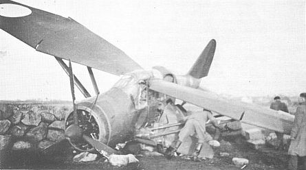
After the outbreak of the Winter War, 17 Lysander aircraft were ordered from England on 8 Jan, 1940. The first 9 were shipped to Gothenburg, Sweden, on 24 Feb. 1940. These were assembled at the Götaverken factory in Torslanda and were flown to Finland between 21 March and 3 May. The rest of the order were flown directly from England to Finland, with 2 arriving on 8 March. One of these was damaged near Stavanger, Norway.
A destroyed Ilmavoimat Westland Lysander LY-124 on the island of Buoy, close to Stavanger, Norway
The remaining Lysanders from the order left England in early March and arrived in Finland on the 15th of the same month. The Lysanders that entered service remained in use until 1945, although some were lost in action.
Ilmavoimat Westland Lysander in service in the Winter War
Lysander Mk.II Engine: Bristol Perseus, 905 hp TO to 50ft: 245 yd Max speed: 230 mph Min speed: 55 mph
Lysander Mk.III Engine: Bristol Mercury XX, 870 hp / 649kW Wing Span: 50ft (15.24m) Length: 30ft 6in (9.3m) Height: 14ft 6in (4,42m) Wing area: 14.15 sq.m / 152.31 sq ft Empty weight: 1980 kg / 4365 lb Max TO wt: 5920 lb (2685 kg) Service ceiling: 6555 m / 21500 ft Range: 522 nm / 600 miles (970 km) Max level speed: 229 mph (369 kph). Stall speed: under 60 mph (96 km/h) Crew: 2 (Pilot and Observer) Armament: 2 x .303in / 7.7mm Browning machine-guns in wheel fairings / 2 x .303in / 7.7mm Lewis guns for observer Bombload: four 20 lb (9 kg) bombs under the rear fuselage / 500 lb (227 kg) of bombs on stub wings if fitted.
Despite the known antipathy of the Air Ministry towards the monoplane as a fighter configuration, and its lack of success with the Wizard, Westland chose a low-wing monoplane design for its response to Specification F.20/27. An air-cooled radial engine and twin-gun armament were specified. From numerous proposals, the Air Ministry chose to order prototypes of two biplanes and two monoplanes, including that offered by Westland. First flown in August 1928 and known as the Interceptor, this was of metal construction and fabric covering except the forward fuselage, which had detachable metal panels. Two 7.7mm Vickers guns were installed low in the open cockpit and were totally enclosed behind a series of louvres along the line of the blast tubes. As first flown, the F.20/27 was powered by an uncowled 440hp Bristol Mercury IIA nine-cylinder air-cooled radial, but this was soon replaced by a 480hp Mercury IIIA and, eventually, a 420hp Bristol Jupiter VII, to which a Townend ring was later added. To overcome handling problems, successive modifications were introduced, including automatic wing slots on the wing roots, redesigned wing fillets and a modified, taller fin and rudder. Performance remained mediocre, however, and the Hawker biplane design to F.20/27 was chosen instead, evolving into the Fury.
Max take-off weight: 1508 kg / 3325 lb Empty weight: 1066 kg / 2350 lb Wingspan: 11.58 m / 38 ft 0 in Length: 7.73 m / 25 ft 4 in Height: 2.95 m / 10 ft 8 in Wing area: 18.95 sq.m / 203.98 sq ft Max. speed: 309 km/h / 192 mph
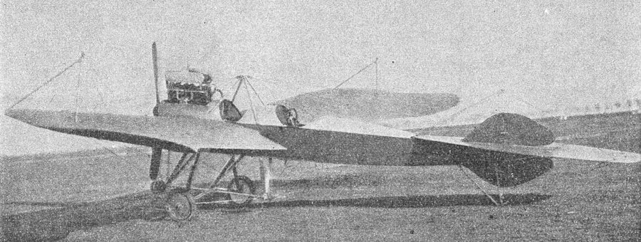
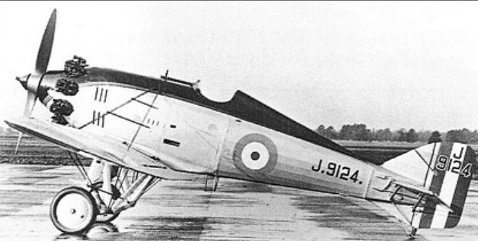
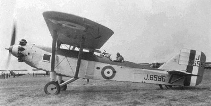
In the middle 1920’s, the Air Ministry issued a Specification for a single-engined high-altitude day-bomber and the Westland design staff, by then thoroughly monoplane-minded, seized the opportunity to produce the Witch, a two-seat parasol monoplane. Judged by its contemporaries this machine was impressive, and a well-considered attempt at securing an aerodynamic advance in design. Compared with biplanes it had a not disadvantageous structural weight, adding its quota of evidence that the high-wing type advocated by Westland was the lighter manner of building a monoplane. First flown in 1928, by Flt.-Lt. L. G. Paget, A.F.C., the Witch had an ingenious external structure, forming part of the wing bracing system, which enabled a large clear space to be left in the fuselage for internal bomb-stowage. The bomb compartment closed by four flap-doors in the front fuselage floor, and was so arranged that they would flick open by the weight of the bombs, in the event of an emergency release preventing manual opening. Although it was a good weight lifter, neither the Witch nor its competitors showed a performance which gave a sufficient improvement above the existing day-bombers, and the class was dropped. However, the Westland example, J.8596, had a useful career as an experimental aircraft and finally served for a long period with the Parachute Training Unit at Henlow.
Engine: 1 x 480hp Bristol Jupiter VIIIF 9-cylinder air-cooled geared radial Max take-off weight: 2744 kg / 6050 lb Empty weight: 1533 kg / 3380 lb Wingspan: 18.5 m / 61 ft 8 in Length: 11.4 m / 37 ft 5 in Height: 3.4 m / 11 ft 2 in Wing area: 49.6 sq.m / 533.89 sq ft
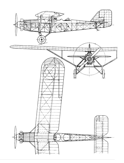
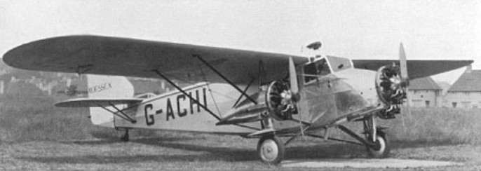
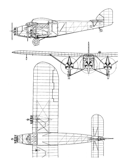
The first Westland commercial aeroplane, the 1919 Limousine four-seat cabin biplane, was an early effort to produce a light air-liner leading, in the following year, to the successful Six-seat Limousine, but it was nearly ten years before the Westland design team produced another passenger aircraft, this time a six-seat tri-motor high-wing monoplane, and again they led the field, being the first British firm to design and produce a low-powered three-engined commercial aircraft. This machine, known at first as the Westland IV, when fitted with Cirrus engines, and later as the Wessex, with Genet engines, was designed, built and flown in a few months, being initially flight-tested by Flt./Lt. L. G. Paget, A.F.C., early in 1929. Originally fitted with three 90-h.p. A.D.C. Cirrus III engines, the prototype – G-EBXK – was later fitted with the five-cylinder Genet engine, but the production models had the seven-cylinder A.S. Genet-Major engines installed as a standard. The Wessex rudder was identical with that of the Wapiti. In order to speed up construction of the prototype a standard Wapiti rudder was fitted “on spec,” but proved so successful that it was retained. Customers for the Wessex were readily forthcoming and included Imperial Airways, Railway Air Services, the Belgian air line SABENA, Sir Alan Cobham’s Air Circus and the Portsmouth, Southsea and Isle of Wight Aviation Co., Ltd. The latter organisation had a specially re-designed Wessex, G-ABVB, for use on their Portsmouth-Ryde (I.o.W.) ferry route. This machine, which was flight-tested by Mr. H. J. Penrose, had a complete metal fuselage structure and increased seating capacity to carry eight passengers and a crew of two; the pilot’s cabin was also raised to give a view over the top of the wing. In the spring of 1931 a chartered Wessex featured in what was probably the first aerial board meeting, the occasion being an air survey by the Directors of the Sheffield and South Yorkshire Navigation Co. of their network of canals. The Second World War found the Wessex still giving good service, several being equipped to train radio operators and navigators for the Royal Air Force.
Engine: 3 x 140hp Armstrong Siddeley Genet Major Max take-off weight: 2857 kg / 6299 lb Empty weight: 1728 kg / 3810 lb Wingspan: 17.5 m / 57 ft 5 in Length: 11.5 m / 38 ft 9 in Height: 2.9 m / 10 ft 6 in Wing area: 45.5 sq.m / 489.76 sq ft Max. speed: 190 km/h / 118 mph