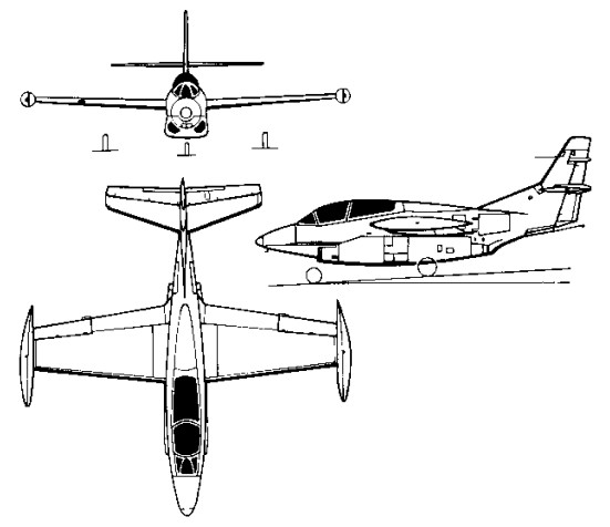
With a requirement in 1956 for a multi-role jet trainer, the US Navy awarded North American a contract to build its North American NA-241 design, which combined proven components and equipment from earlier aircraft manufactured by the company. Ordered as the T2J-1 (later T-2A), this trainer combined a wing derived from the FJ-1 Fury and the control system of the T-28C Trojan with a single 1542kg thrust Westinghouse J34-WE-36 turbojet, and accommodated the instructor and pupil in tandem, seated (eventually) on zero-zero ejection seats.
The first of six initial production T-2As was flown on 31 January 1958 and deliveries to the US Navy began in July 1959, by which time the name Buckeye had been allocated to this trainer. Equipping US Navy Training Squadrons VT-4, -7, -9 and -19, a total of 217 T-2As was built.
Two T-2A were modified to serve as YT-2B prototypes, in which the single J34 turbojet was replaced by two 1361kg thrust Pratt & Whitney J60-P-6 turbojets. The first was flown on 30 August 1962, being followed by 97 similar T-2B aircraft , 152382-152391, 152440-152475, 153538-153555, and 155206-155238 (NA-280, -288, -291, -294, -310) from 1962.
Rockwell-North American T-2B
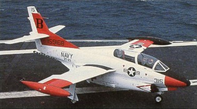
Final production version was the 1958 T-2C (NA-307, -318, -332, -340) which introduced General Electric J85 turbojets, preceded by a single YT-2C prototype conversion from a T-2B.
A total of 273 was built under US Navy contracts before production ceased, comprising 231 T-2Cs for navy use (155239-155241, 156686-156733, 157030-157065, 158310-158333, 158575-158610, 158876-158911, 159150-159173, 159704-159727) plus 12 T-2D and 30 T-2E aircraft in 1969, procured for Venezuela and Greece respectively.
The DT-2C was a drone director conversion.
It was to be re¬tired in favour of the more advanced T 45 Goshawk which has cockpit instrumentation similar to the F/A-18 Hornet.
T 2A Engine: 1 x 3,400 lbs.t. (1542 kpg) Westinghouse J34 WE 36 Max speed, 492 mph (792 kph) at 25,000 ft (7620 m) Cruise, 422 mph (679 kph) Initial climb, 5,000 fpm (25.4 m/sec) Service ceiling, 42,500 ft (12 950 m) Range, 550 mls (885 km) Empty weight, 6,893 lb (3 127 kg) Loaded weight, 9,916 lb (4498 kg) Span, 36 ft (10.97 m) Length, 38 ft 8 in (11.78 m) Wing area, 255 sq.ft (23.7 sq.m)
T 2B Engines: 2 x 3,000 lbs.t. (1316 kgp) J60. MTOW: 12,300 lb Top speed: 545 mph
YT-2B / T 2B Engines: 2 x J60-P, 3,000 lbs.t. (1316 kgp) Useful load: 3842 lb Speed: 540 mph Ceiling: 44,000 ft
T-2C / DT-2C Engines: 2 x General Electric J85-GE-4 turbo-jet, 13.1kN / 2950 lb Max take-off weight: 5978 kg / 13179 lb Empty weight: 3681 kg / 8115 lb Wingspan: 11.63 m / 38 ft 2 in Length: 11.79 m / 38 ft 8 in Height: 4.51 m / 14 ft 10 in Wing area: 23.70 sq.m / 255.10 sq ft Useful load: 5065 lb Max speed: 521 mph Cruise speed: 465 mph Ceiling: 13535 m / 44400 ft Range: 1465 km / 910 miles Crew: 2
T-2J Engines: 2 x Westinghouse J34, 3400 lb Wingspan: 36’0″ Length: 38’4″ Max speed: 494 mph Cruise speed: 417 mph Stall: 67 mph Range: 967 mi
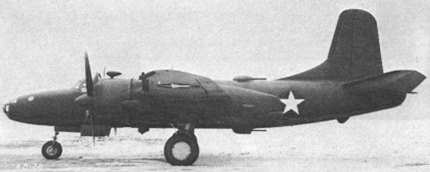
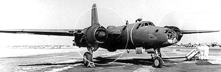
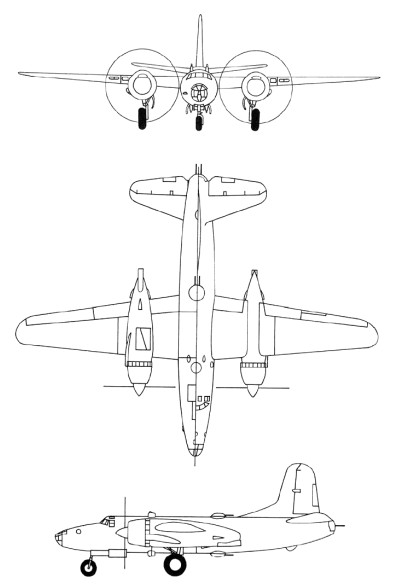
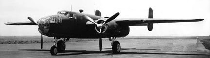
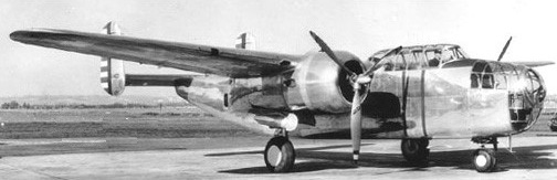
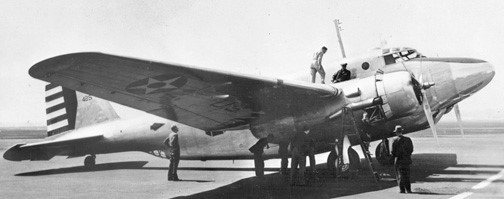
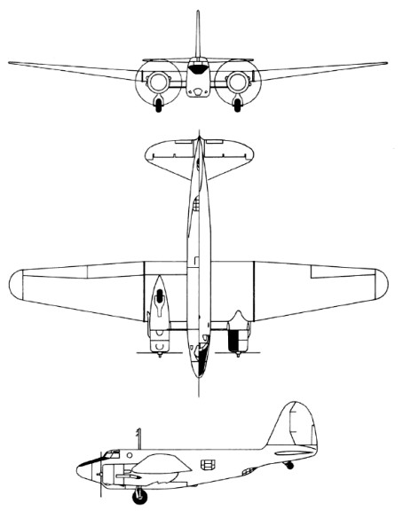
Envisaged originally as a high-altitude version of the B-25 Mitchell, the North American NA-63 (XB-28) emerged finally as an almost entirely different aircraft. With single vertical tail surfaces and a circular-section fuselage with a pressure cabin for the five-man crew, the XB-28 was powered by two 1491kW Pratt & Whitney R-2800 radials and bomb bay capacity was 1814kg and -28A with R-2800-27. Dorsal, ventral and tail turrets, each containing two 12.7mm machine-guns, were remotely controlled from the cockpit; three similar forward-firing weapons were also fitted.
North American XB-28 40-3056
Of three prototypes ordered in February 1940, the first flew in April 1942 (40-3056), the second (40-3058), with a reconnaissance camera installation, crashed during the test programme and the third was cancelled. Although the XB-28 achieved a maximum speed of 599km/h at 7620m and could carry a 272kg bomb load for 3283km, production orders were not placed when no particular need for such a plane was found. A third prototype was unbuilt.
XB-28 / NA-63 Engines: two Pratt & Whitney R-2800-11, 11491kW / 2000 hp Wingspan: 22.12 m / 72 ft 7 in Length: 17.20 m / 56 ft 5 in Wing area: 62.80 sq.m / 675.97 sq ft Max take-off weight: 16226 kg / 35772 lb Empty weight: 11611 kg / 25598 lb Useful load: 10,165 lb Max speed: 372 mph Cruise speed: 411 km/h / 255 mph Stall: 86 mph Ceiling: 34,600 ft Range: 3284 km / 2041 miles
XB-28A / NA-67 Engines: two Pratt & Whitney R-2800-27, 11491kW / 2000 hp Wingspan: 22.12 m / 72 ft 7 in Length: 17.20 m / 56 ft 5 in Wing area: 62.80 sq.m / 675.97 sq ft
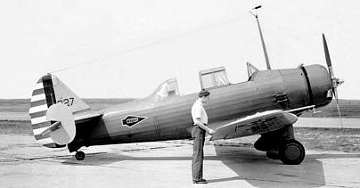
Built as a private venture, the NA-40-1 prototype flew in January 1939. The design was extensively modified as NA-62 after Wright Field testing and 1700hp R-2600s installed.
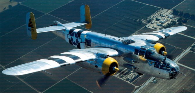
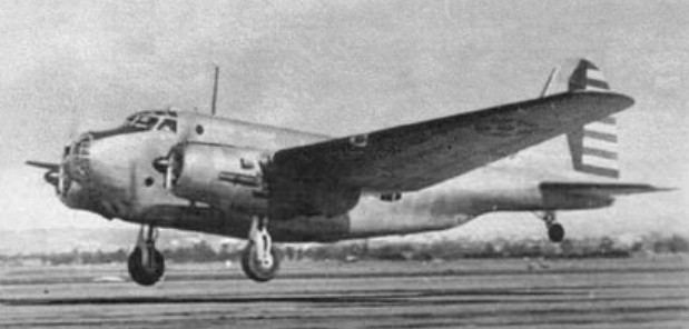
Ordered into production in 19 August 1939 it took just fifty-three weeks after receiving the initial contract before the first prototype took to the air. The initial order for 24 as B-25: 40-2165 to 40-2188. The prototype of the B-25 was flown for the first time on August 1940. The first of these 184 B-25 Mitchell entered service in 1941.
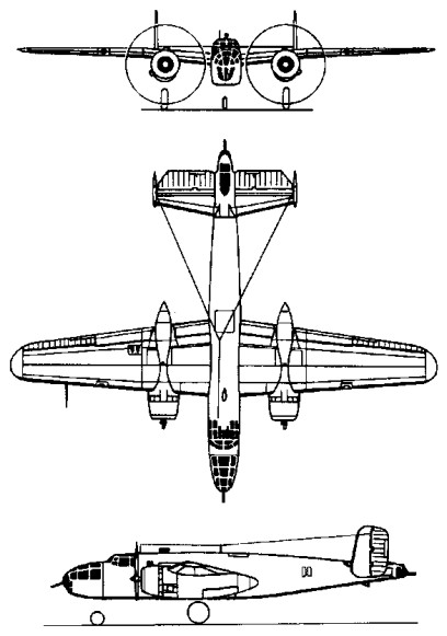
North American B-25 Straight-wing, narrow tails 40-2165
It and the first few B-25s off the production line had wings with a constant dihedral from the fuselage to the tips. Only after the 10th one were the wings redesigned with the characteristic gull configuration. Its armament included four .30-caliber machine guns, one in the nose and three amidships, and a single .50-caliber gun in the tail. The usual bomb load was 2,000 pounds with a maximum overload of 3,600 pounds. Large scale production began immediately and early models were in service by the time America entered the war in December 1941.
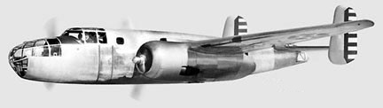
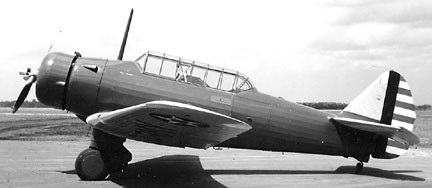
North American B-25A
The B-25A was fitted with self-sealing fuel tanks and armor for the pilot. The B replaced the midship and tailguns with electrically operated turrets. Each turret had two .50-caliber machine guns. The lower turret was remote-controlled. 120 of the 1941 B-25B (NA-62B) were built; 40-2229 to 40-2242, and 40-2244 to 40-2348, of which 23 to went to the RAF/RAAF.
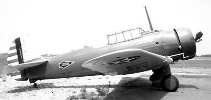
North American B-25B 40-2321
The C and D were provided with automatic flight control equipment.
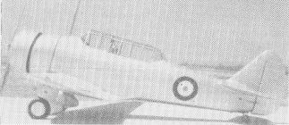
North American B-25C 41-12800
The B-25C was the first version of the Mitchell to be mass-produced. Following the completion of the initial B-25, B-25A, and B-25B contracts, a number of contracts were awarded to North American for 1625 B-25Cs to be built at its Inglewood factory. At the same time, an additional contract was issued for 2290 essentially identical B-25Ds, to be built at a new North American plant in Kansas City, Kansas.
The first B-25C contract was approved on September 24, 1940 for 863 aircraft under the company designation NA-82. On June 24, 1941, the Netherlands government ordered an additional 162 aircraft under the designation NA-90 which were later built as the B-25C-5. Lend-Lease funds financed contracts signed on January 23, 1942 for 150 NA-94 (B-25C-10) for Britain and 150 NA-93 (B-25C-15) for China. However, these allotments were not followed in the delivery of actual aircraft.
The B-25C was outwardly almost identical to the B-25B. It introduced the R-2600-13 Double Cyclone engine with Holley 1685HA carburetors in place of the earlier Bendix Stromberg PD-13E-2 units. The Bendix carburetors were favored because of their easier maintenance, but they required more careful anti-icing procedures. De-icer and anti-icing systems were added, and a Stewart-Warner cabin heater was added in the left wing. A 24-volt electrical system was also added.
The armament of the B-25C was the same as that of the B-25B, namely a single 0.30-inch machine gun in the nose, two 0.50-inch machine guns in the dorsal turret, and two 0.50-inch machine guns in a retractable ventral turret. The ventral turret was often removed in the field.
The B-25C introduced a new type of tail skid underneath the extreme rear fuselage, a solid unit which replaced the spring-loaded tail skid of earlier versions. This type of tail skid was retained throughout the Mitchell production run.
On the earlier B-25s, the exhaust pipe coming out of the back of the engines extended all the way to a position underneath the forward leading edge of the wing. On the B-25C, the exhaust pipes were considerably shortened, and terminated immediately behind the engines.
The fuel was carried in four tanks in the inner wing panels, with a total capacity of 670 US gallons. In addition, a 515-gallon tank could be installed in the bomb bay for ferrying purposes, bringing total fuel capacity to 1255 US gallons.
Beginning with B-25C serial number 41-12817, a small transparent scanning blister was installed above the navigator’s station. At this time, the turrets were changed to Bendix Amplidyne type, and a carbureter air filter was added. Changes were made so that an additional 304 US gallons of fuel could be carried in auxiliary cells in the outer wing panels, for a total of 974 US gallons.
The B-25C-1 production block introduced under-wing bomb racks which could accommodate six to eight 100- to 325-pound bombs. In addition, provisions were made for a rack underneath the fuselage capable of carrying a short 22.4-inch torpedo weighing 2000 pounds. If the torpedo was carried, no bombs could be, although a bomb bay fuel tank could be used. The Mitchell was employed only in limited numbers as a torpedo plane against Japanese shipping. However, extensive use was made of the external wing racks, which could carry six to eight bombs of 100-325 pounds in weight.
Beginning with the B-25C-5 production block, the 0.30-inch nose gun was removed and replaced by a flexible 0.50-inch machine gun in the extreme nose and a fixed 0.50-inch machine mounted on the starboard side of the nose and firing through a hole cut into the side of the Plexiglas glazing. At the same time, better winterization provision were made.
The B-25C-5 production block also introduced a new type of engine exhaust. The B-25B and earlier C versions had a problem with bright spurts of flame being emitted from the exhaust, a dead giveaway during night operations. This problem was so bad that the Mitchell had to be restricted from night operations where enemy aircraft could be expected. In these earlier versions, the exhaust from each cylinder head was gathered by a collector ring, which directed the exhaust to the outside via a single pipe on the side of the nacelle away from the fuselage. Several different exhaust modifications were tried out in an attempt to alleviate this problem. The most effective arrangement was found to be a the replacement of the single exhaust pipe by a set of “finger”-type flame dampening exhaust collectors which ported the exhaust through groups of small rectangular outlets that stuck out underneath the trailing edge of the cowl flaps. These “finger”-type flame dampeners were installed on the production line beginning with the B-25C-5 production block. These were fairly effective flame quenchers, but they suffered considerable cracking and few B-25Cs reached combat zones without the replacement of these finger exhausts by full collector rings or by the later Clayton S-shaped stacks that were introduced on the -15 production block.
The B-25C-10 production block introduced an AM remote reading compass, provisions for additional cabin heating, and an improved scanning lens for the sig.
Beginning with the B-25C-15 production block, the exhaust collector ring was replaced with Clayton “S”-shaped flame dampening stacks attached to each individual cylinder. Cutouts and fairings were added to the cowling panels where each of the stacks protruded, creating a rather cluttered cowling shape. These protrusions introduced a slight speed penalty, but this was considered an acceptable tradeoff in view of the better flame dampening that was achieved. This feature was provided on all subsequent Mitchells. However, the new exhaust system was not all that popular with Mitchell crews, since it resulted in an increase in cockpit noise as compared to the old arrangement in which collector rings ported the exhaust to the outboard side of the nacelles.
At the same time, emergency hydraulic landing gear lowering devices were provided. The fuel capacity consisted of four tanks in the inner wing panels, with a total capacity of 670 US gallons. In addition, a 515-gallon tank could be installed in the bomb bay for ferrying purposes, bringing total fuel capacity to 1255 US gallons. Later versions had additional auxiliary fuel tanks in the outer wing panels. Later versions could also have 125-gallon tanks fitted in side waist positions, a 215-gallon self-sealing fuel tank installed in the bomb bay, and provisions could be made for a droppable 335-gallon metal bomb-bay fuel tank. Armament: Two 0.50-inch machine guns in dorsal turret. Two 0.50-inch machine guns in retractable ventral turret. One 0.30-inch machine gun in flexible mount in the nose. Starting with B-25C-5 the 0.30-inch nose gun was removed and replaced by a flexible 0.50-inch machine gun in the extreme nose and a fixed 0.50-inch machine mounted on the starboard side of the nose and firing through a hole cut into the side of the Plexiglas glazing. Normal bomb load was 3000 pounds but could be increased on the B-25C-1-NA with external underwing racks to a maximum of 5200 pounds.
Deliveries on a new contract (NA-96) began in February 1943 with the similar B-25C-20.
Beginning with production block B-25C-25, a “clear-vision” windshield was installed. Provisions were made for the fitting of additional fuel tanks for ferrying purposes. 125 gallons of fuel could be carried in side-mounted tanks in the waist position. A 215-gallon self-sealing fuel tank could be installed in the bomb bay, and provisions for a droppable 335-gallon metal bomb-bay fuel tank were made on every second airplane. B-25C serial number 43-32732 was fitted with a special bomb bay rack to carry an airborne flame thrower. The results of tests with this unusual feature are unknown.
The first B-25C was accepted in December of 1941, with the 1619th and last one being delivered in May of 1943. The B-25C; 42-32233 to 42-32280, 42-32282 to 42-32383, 42-32389 to 42-32532, 42-53332 to 42-53493, and 42-64502 to 42-64901, were built as NA-82, NA-90, NA-93, and NA-94. The NA-93 and -94 were exports to China and RAF, respectively.
The 1942 XB-25E and -25F were fitted with experimental deicing equipment. One each were conversions from -25C with new s/n; 43-32281 and 43-32282.
The G was the first model to carry a 75mm Army M-4 cannon in the nose. One conversion from a B-25C with new s/n, 43-32384, was completed in 1942 as the XB-25G.
North American B-25G Cannon installation
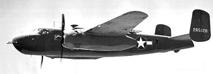
The B-25G (NA-96) of 1942 was a four-crew production model with the M-4 cannon. 405 were built; 42-64902/65201, and -64802/65201.
North American B-25G 42-65128
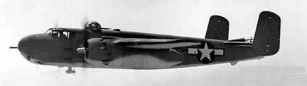
The 1943 B-25H (NA-98) increased its armament to four .50-caliber guns in an armored nose and two pairs of .50-caliber guns on each side of the fuselage. It was the precision bomber version of the H; the crew increased to six to include a bombardier.
North American B-25H
1,000 B-25H were built: 42-4105/5104.
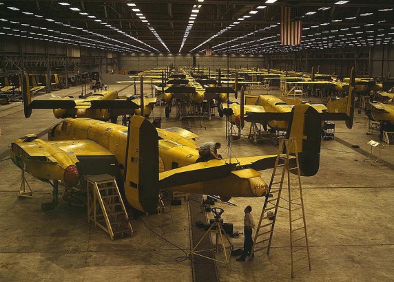
The B-25J, built at the Kansas plant, was the most widely produced version, 4318 being produced 1943-45.
More than 700 B 25s were acquired by the U.S. Navy and Marines, as the PBJ. USN/USCG transfers of USAAF B-25 for use in mine-laying, harassing night raids, and bombing and torpedoing ships in the Southwest Pacific theatre.
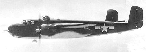
The US Marine Corp operated B-25s as the PBJ-1C (1943 50 ex-B-25Cs; 34998-35047), PBJ-1D (1943 152 ex-B-25Ds; 35048-35096, 35098-35193, 35196-35202), PBJ-1G (1 ex-B-25G; 42-65031/35097), PBJ-1H (248 ex-B-25Hs; 35250-35297, 88872-89071), and PBJ-1J models (255 ex-B-25Js; 35194-35195, 35203/35249, 35798-35920, 38980-39012, 64943-64992).
North American PBJ-1H
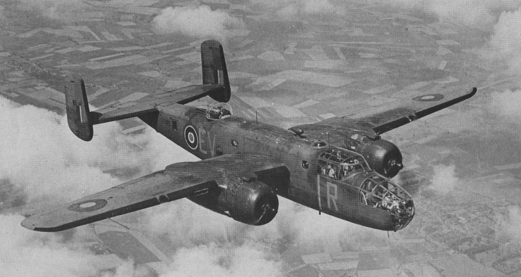
The Royal Air Force received about 800, and the airplane was flown more than a dozen other countries. Top speed only reached about 270 mph but the Mitchell’s 1,350 mile range made it very useful.
The Americans did not use Mitchells operationally from the United Kingdom but based them with the 12th United States Army Air Force in the Mediterranean. However the British, Dutch and Russians received large numbers.
Mitchell II
Training aircraft were the AT-25, later designated the TB-25.
All B-25 models were powered by Wright R-2600 Cyclone 14 engine. More than 12000 aircraft built.
In April 1942 sixteen Mitchells, operating from the American aircraft carrier USS Hornet, made one of the most daring bomber raids in the Second World War, on Tokyo.
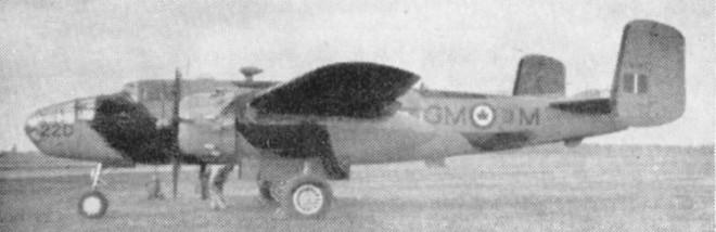
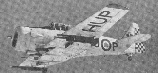
In 1955 large numbers of these wartime medium bombers were still used by the R.C.A.F. for a variety of duties. The target towing version shown here is powered by two 1,700 h.p. Wright R2600-13 engines.
B-25D
About 100 B-25Js, with glazed noses, are used for all weather crew training and guided weapon development. Other B-25Ds and Js were used by Reserve squadrons. TB-25s were in service with the U.S.A.F.
The Mitchell was used in all theatres and a total of 9816 were built, essentially unaltered in airframe and engines, but revised in armament, armour and fuel. There were 1619 B-25C built, and 1000 B-25J. A total of 9,816 were delivered to USAAF, and about 2,000 more exported to Allied air services. The USN version was the PBJ. The last, a TB-25, was finally retired from USAAF duty in Jan 1959.
B-25A / NA-62A Max speed: 315 mph Cruise speed: 262 mph Stall: 90 mph Range: 1350 mi Ceiling: 27,000 ft
B-25B Dorsal & ventral turrets
B-25C / PBJ-1C Engines: Two Wright R-2600-13 Double Cyclone, 1700 hp takeoff, 1500 hp at 2400 rpm. Wingspan: 67 ft 67.7 in Length: 53 ft 0 in Height: 15 ft 9 in Wing area: 610 sq.ft Empty weight: 20,300 lb Maximum weight: 34,000 lb Maximum speed: 284 mph at 15,000 ft. Cruising speed: 233 mph at 15,000 ft. Initial climb rate: 1100 fpm Time to 15,000 ft: 16.5 min Service ceiling: 24,000 ft Range: 1500 miles with 3000 lb bombs. Internal fuel capacity: 670 US gal Ferry fuel capacity: 1255 US gal Opt fuel later mods: 800 US gal Armament B-25C: 4 x 0.50-inch machine guns, 1 x 0.30-inch machine gun Armament B-25C-5: 6 x 0.50-inch machine guns Normal bomb load: 3000 lb Underwing bomb load B-25C-1-NA: 2200 lb Max bomb load B-25C-1-NA: 5200 lb
B-25D Mitchell / PBJ-1D Ventral bomb racks Engines: two 1,700 h.p. Wright R2600-13 Span: 67 ft. 7 in Max Weight: 33,500 lb Max Speed: 303 m.p.h.
B-25G / PBJ-1G / NA-96 Length: 51’0″ Max speed: 281 mph Cruise speed: 248 mph Stall: 105 mph Range: 1560 mi Ceiling: 24,300 ft Armament: 75 mm M-4 cannon Crew: 4
B-25H / PBJ-1H / NA-98 Improved B-25G Engines: Wright R-2600-13 Cyclone, 1700 hp / 1268 kW Wingspan: 67 ft 7 in / 20.60 m Length: 51 ft 0 in / 13.34 m Height: 15 ft 9 in / 4.80 m Wing area: 610,0 sq.ft / 56.67 sq.m Empty weight: 19,975 lb / 9061 kg MTOW: 36,047 lb / 16,351 kg Max speed: 275 mph / 442 kph at 13,000 ft / 3960 m Cruise speed: 230 mph Stall: 105 mph Climb to 15,000 ft / 4570 m: 19 min 0 sec Service ceiling: 23,800 ft / 7255 m Range: 2700 mi / 4344 km Armament: 1 x 75mm T-13E1 cannon, 12 x .50 in mg Bomb load: 3200 lb / 1452 kg or 1 x 2000 lb / 907 kg torpedo Seats: 5
B-25J / PBJ-1J Improved B-25H initially with B-25D glazed nose, later solid 8 gun nose Engines: 2 x Wright R-2600-92 Cyclone, 1268kW / 1700 hp Wingspan: 20.6 m / 67 ft 7 in Length: 16.13 m / 52 ft 11 in Height: 4.98 m / 16 ft 4 in Wing area: 56.67 sq.m / 609.99 sq ft Max take-off weight: 15876 kg / 35001 lb Empty weight: 8836 kg / 19480 lb Fuel capacity: 811 gal Max. speed: 237 kts / 438 km/h / 272 mph at 13,000 ft Cruising speed: 200 kts / 370 km/h Ceiling: 7375 m / 24200 ft Cruising altitude: 12992 ft / 3960 m Wing load: 57.4 lb/sq.ft / 280.0 kg/sq.m Range: 2173 km / 1350 miles with 3000 lb bombload Armament: 12 x 12.7mm / .50 machine-guns, 1300-1800kg of bombs Crew: 5
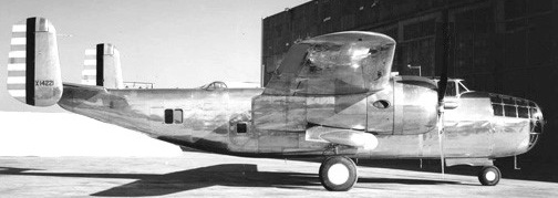
A twin-engined Attack Bomber was produced in 1939 and was available for export as the NA-40 series. A single prototype was built.
The NA-40-1 NX14221 was first flown in January 1939 by Paul Balfour, powered by two 1100hp P&W R-1830. It was re-powered on factory model NA-40-2 with 1350hp Wright GR-2600.
North American NA-40-1 NX14221
Designed by Howard Evans and team, NA-40B NX14221 crashed during Wright Field tests, but the shoulder-wing, twin-tail, tri-gear design eventually led to B-25.
NA-40 Engines: 2 x P&W R-1830-S6C3, 1100hp Wingspan: 66’0″ Length: 48’3″ Useful load: 5780 lb Max speed: 309 mph Cruise speed: 282 mph Range: 1200 mi Crew; 5
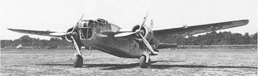
Similar in appearance to the Douglas B-18 Bolo, but intended to achieve significantly improved performance, the North American NA-21 bomber was developed at the company’s Inglewood, California plant during 1935-3, the prototype being completed in March 1937 at a cost of $122,600.
North American XB-21 38-485
Powered by two 895kW Pratt & Whitney R-1820 Twin Hornet engines with F-10 turbo-superchargers, the XB-21 carried a six-man crew and armament comprised single 7.62mm machine-guns in nose and dorsal turrets, plus a similar weapon in each of the ventral and two waist positions. Short-range bomb load was 4536kg, reducing to 998kg over 3058km.
North American XB-21 Nose mod at Wright Field
Only the prototype was built, 38-485, as XB-21 Dragon, an unofficial title, with no appeal to the USAAC despite a second attempt the following year by Douglas to use it for their B-23, which led to the NA 40 prototype, which led directly to the B-25.
XB 21 Engines: 2 x Pratt & Whitney R-1820 Twin Hornet 1200 hp Wingspan: 28,96m / 95 ft 0 in Length: 61’9″ Max weight: 18144 Kg / 40001 lb Useful load: 8171 lb Power loading: 7,560 Kg/hp Max speed: 354 kph / 220 mph Cruise speed: 190 mph Ceiling: 25,000 ft Range: 3060 km Armament: 3 x 7,62 mm mg Bombload: 4535 kg Crew: 6
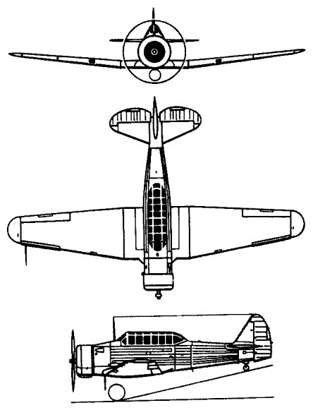
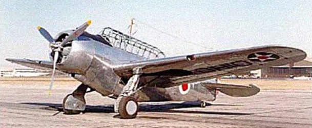
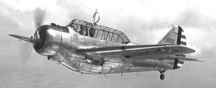
North American engineers designed two variants of the BC-1 to sell to overseas buyers as fighters and attack planes. One was a single-seat fighter and the other a two-seater; both had five .30-caliber ma¬chine guns in the wings and nose.
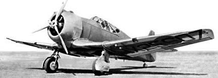
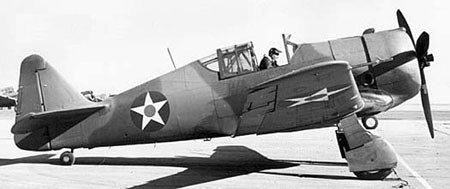
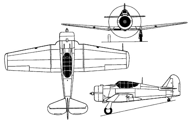
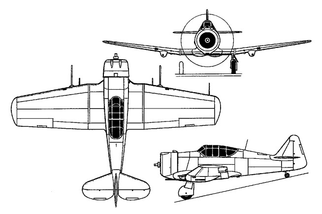
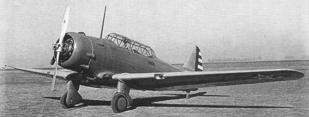
Conceived as a low-cost fighter for use by smaller nations demanding comparatively simple warplanes, yet embodying such modern features as an enclosed cockpit and a retractable undercarriage, the NA-50 was a single-seat derivative of the NA-16 tandem two-seat basic trainer. Of all-metal construction with semi-monocoque fuselage, the NA-50 was powered by an 870hp Wright R-1820-77 Cyclone radial.
First flying on 1 September 1940 piloted by Lewis Waite, one prototype was built for the USAAF (NX25607).
North American P-64 NX25607
The first order, from the Siamese air force, was for 10, including both versions. Brazil, Peru and Chile ordered 49 single-seat fighters.
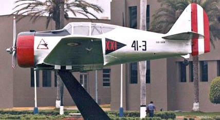
In January 1938, a contract was placed on behalf of the Cuerpo de Aeronautica del Peru for seven NA-50s, delivery being completed in May 1939. In Peruvian service, the NA-50s were equipped with racks for up to 249kg of bombs, and the type saw active service in 1941 during a conflict with Ecuador. The last Peruvian NA-50 was withdrawn in 1961.
North American NA-50
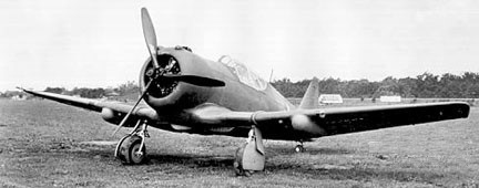
The company Model NA-50A P-64 ordered by Siam on 30 December 1939, was little more than a single-seat pursuit ship patterned after the Harvard trainer and developed from the NA-50 used by Peru. Tension was increasing at the time between Siam and French Indochina, and the State Department prohibited the transfer. The six examples of this strictly export craft were built at Inglewood and painted in Siamese markings, and were en route to Siam when the US Army confiscated them. The aircraft were diverted to the Philippines, where they were taken over by the U.S. Army Air Corps (41-18890/18899). They removed the armament, and assigned them to training duties at Luke Field, Arizona, designated the P-64.
North American P-64 8300
A widely-published report that the Siam-bound aircraft were caught at Pearl Harbour during the 7 December 1941 Japanese attack is inaccurate: the NA-50As were apparently embargoed in October 1940 and a camouflaged example in USAAF markings was noted at Luke as early as 16 September 1941.
Never really a fighter in USAAF service, the six P-64s were essentially base ‘hacks’ and possibly never received American serial numbers. A privately-owned survivor in civil registry as N840 was airworthy in the US as recently as 1975.
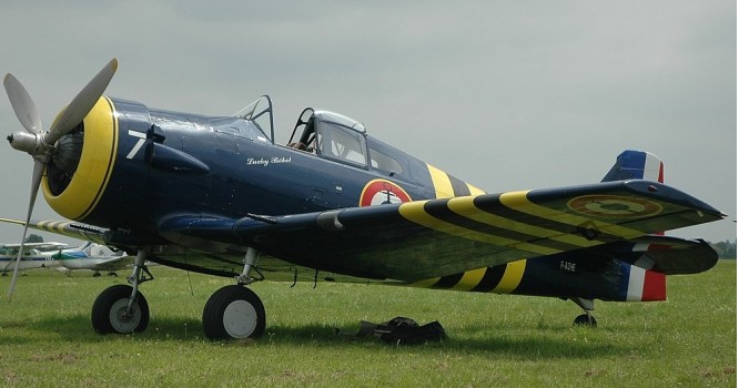
North American NA-68
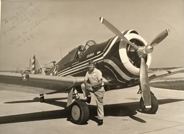
One survives in the EAA collection (41-19085, NX37498, XBKUU, N686220).
Courtesy Don Stits
In early 1964, a North American P64 was ferried from San Diego to Flabob Airport in Riverside Ca. Once we realized it’s rarity, Ray contacted Paul Poberezny and a deal was made to acquire the P64 for the EAA Museum. I spent over two months working on the P64 to get it airworthy so Paul could ferry it to Wisconsin. Attached pictures are the P64 as it sat on Flabob Airport and after Paul finished the restoration (Paul in uniform with his pride and joy). Don Stits
NA-50 Max take-off weight: 2585 kg / 5699 lb Empty weight: 2028 kg / 4471 lb Wingspan: 11.35 m / 37 ft 3 in Length: 8.21 m / 26 ft 11 in Height: 2.67 m / 8 ft 9 in Wing area: 21.93 sq.m / 236.05 sq ft Max. speed: 475 km/h / 295 mph Range: 1038 km / 645 miles
NA-50A Engine: Wright R1820-77 Cyclone 9, 870 hp Wing span: 37 ft 3 in Wing area: 236 sq.ft Length: 26 ft 11 in Empty weight: 4470 lb MAUW: 6800 lb / 3084 kg Max speed: 270 mph at 9500 ft Cruise: 255 mph at 16,500 ft Range: 645 mi Armament: 2 x .30 mg & 2 x 20mm cannon + 4 bombs underwing.
P-64 Engine: Wright R-1820, 875hp Max take-off weight: 2717 kg / 5990 lb Empty weight: 2113 kg / 4658 lb Wingspan: 11.35 m / 37 ft 3 in Length: 8.23 m / 27 ft 0 in Height: 2.74 m / 8 ft 12 in Wing area: 21.18 sq.m / 227.98 sq ft Max. speed: 434 km/h / 270 mph Cruise speed: 235 mph Stall: 71 mph Ceiling: 4260 m / 14000 ft Range: 1380 km / 858 miles Seats: 1
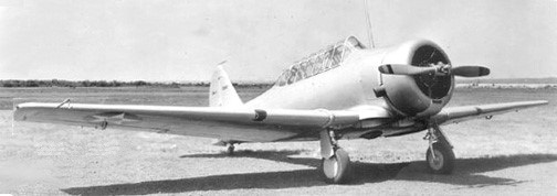
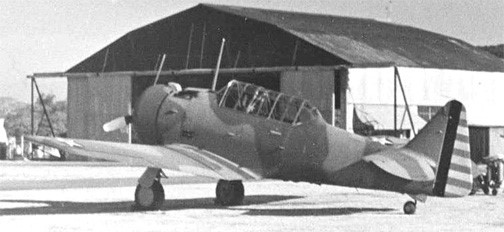
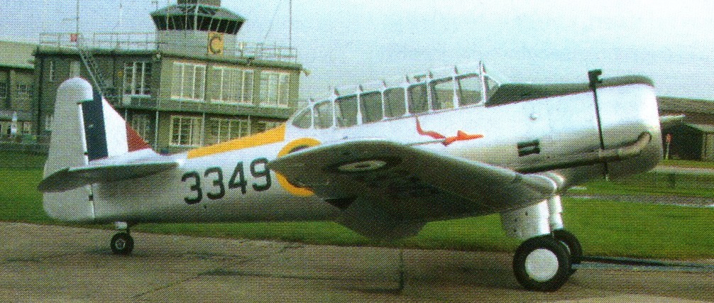
Derived from the 1935 NA-16 prototype, the North American NA-26 design was first flown in 1938. This aircraft was designated the Basic Combat Trainer, BC-1. The BC-1 (basic combat, type 1) had the same basic airframe design as the BT-9 but with a retractable main landing gear and more power. It was equipped with one nose-mounted .30-caliber machine gun that fired through the propeller and a second .30-caliber gun on a flexible mount in the rear cockpit.
The first one flew on February 11, 1938. The Edward G. Budd Manufacturing Co. was subcontracted to experiment with stainless steel in the wing panels to determine its structural feasibility in the aircraft. It had seven inches more wing span, larger tanks and a higher gross weight (by approx 155 pounds) when compared to the later T-6.
In 1939, the U.S. Army Air Corps ordered an additional 200 of the advanced BC-1A type, and the U.S. Navy a number of the same type but designated as SNJ-1.
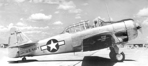
The Navy had been searching for a trainer for pilots destined to fly its scout aircraft, such as the Douglas SBD dive bomber, and it chose the BC-1. The BC-1 was ordered in 1937 to the extent of 41 aircraft with the R-1340-45 radial. Blunt wing tips and a straight-edged rudder characterised the BC-lA, of which 92 were ordered and the last six delivered as AT-6s after a change in designation policy during 1940. AT-6 orders covered an extra 85 aircraft, and production then switched to 1,429 AT-6As with the R-1340-49 engine and modified fuel tankage. The full production flood now saw 400 AT-6B gunnery trainers with the R-1340-AN-1, 2,970 AT-6Cs with a high proportion of non-strategic materials, 3,713 AT-6Ds with the original structure and 24-volt electrics, and 25 AT-6Fs with a strengthened airframe. US Navy variants equivalent to the BC-1, AT-6, AT-6A, AT-6C, AT-6D and AT-6F were the SNJ-1 to -6 respectively, of which 4,765 were delivered.
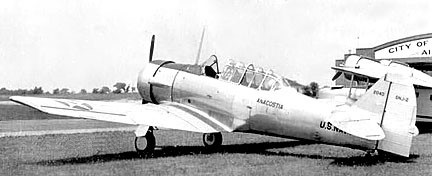
SNJ-1
The 1937 SNJ-1 was as the Army BC-1A with retractable gear and metal-covered fuselage. Sixteen very operated a 1552-1567.
A total of 2,068 wartime aircraft were remanufactured as T 6G.
North American engineers designed two variants of the BC-1 to sell to overseas buyers as fighters and attack planes. One was a single-seat fighter and the other a two-seater; both had five .30-caliber ma¬chine guns in the wings and nose. The attack version (NA-44, -69, -72) also had a flexible machine gun in the rear cockpit. The first order, from the Siamese air force, was for 10 A-27 (NA-69), including both versions.
North American A-27
Brazil, Peru and Chile ordered 49 single-seat fighters. Brazil received 30 NA-72 with P&W R-1340 in 1940 and one armed prototype NA-44 went to the RCAF in 1940.
Siam never received any of the aircraft, however. Tension was increasing at the time between Siam and French Indochina, and the State Department prohibited the transfer. The aircraft were diverted to the Philippines, where they were taken over by the U.S. Army Air Corps, re-designated A-27 (41-18890/18899), where they were destroyed in Japanese bombings during Dec 1941. Several A-27s saw action in the Philippines on December 8, 1941, against invading Japanese forces. The single-seat version was stripped of armament, returned to the States for fighter-pilot training and designated the P-64.
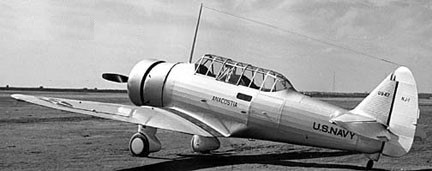
The Navy later requested several modifications to the SNJ-1, including a more powerful engine. That changed the designation to SNJ-2.
Sixty-one 1940 SNJ-2 were operated as 2008-2043 and 2548-2572.
North American SNJ-2 2040
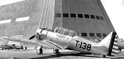
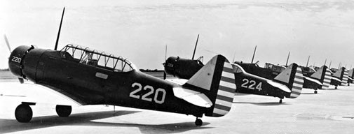
The 1940 AT-6 (NA-59) first flew on 6 February 1930 and 85 were built, plus 9 from BC-1B (40-717/725, -2080/2164).
A total of 1549 of the 1941 AT-6A (NA-77) were built: 41-148/785, -15824/16228, 16259/16403, -16439/16457, 41-16474/16578, -16616/16653, -16693/16778, -16821/16878, -16924/16939, -16994/17033.
North American AT-6A 41-16087 from Mather Field at Moffett Field CA.
The Air Corps asked for other modifications, and the AT¬6A/SNJ-3 emerged as the standard advanced single-engine trainer for both services. (It was used for basic pilot training and even for primary training toward the end of World War II, when Nationalist Chinese students were sent to the States for pilot instruction.)
North American SNJ-3
270 SNJ-3 were produced in 1941 (6755-7024) plus 296 AT-6 obtained from the USAAF (01771-01976, and 05435-05526). Fifty-five SNJ-3 were converted to SNJ-3C deck-landing trainers.
The SNJ-4 (NA-88) of 1942 were the same as USAAF AT-6C, 2,400 produced (05527-05674, 09817-10316, 26427-27851, and 51350-51676). 85 were converted in 1942 to SNJ-4C deck-landing trainers.
North American SNJ-4
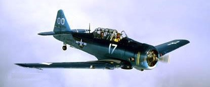
The SNJ-5 (NA-88) of 1943 were 1,573 USAAF AT-6D transferred to the USN (43638-44037, 51677-52049, 84819-85093, and 90582-91101). Some were converted to SNJ-5C deck-landing trainers.
North American SNJ-5 84968
The 411 SNJ-6 of 1944 were from USAAF production of AT-6F (111949-112359).
In 1952 earlier models were modernised to T-6G standards as SNJ-7s. The SNJ-7B was an armed version.
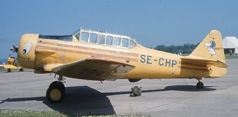
AT-6A SE-CHP
To accommodate orders that amounted to more than 600 aircraft when war began, North American opened a new plant in Dallas in 1942 to supplement the aircraft being turned out in the Los Angeles area.
The Dallas plant became the main point of manufacture – hence the name ‘Texan.” New model suffixes were assigned as minor changes were made. To save alu¬minum, some of the AT-6/SNJs were turned out with plywood fuselages and internal stringers made from spruce. The Navy added tail hooks for carrier train¬ing. Bomb racks and belly fuel tanks were also added.
A number of Texans were either built or modified for experimental purposes. The Army Air Forces ordered one XAT-6E in 1944 with an in-line, air-cooled engine installed. On test flights it reached a top speed of 244 mph and climbed to 30,000 feet – 50 mph faster and 6,000 feet higher than the Texans flying with radial en¬gines. Unfortunately, the in-line engine proved to be a maintenance headache, and only one XAT-6E was built. Another experimental Texan was des¬ignated the ET-6F in 1950, when a swivel landing gear was installed to assist in making crosswind landings. The Northrop Co. experimented with automatic pilots in the T-6. Cameras were installed aft of the rear seat in a few aircraft for aerial photography; flares were added to make photography possible at night as well.
When the British realized they could not build enough trainers in the United Kingdom at the beginning of World War II, they ordered the BC-1, which they designated the Harvard Mark I. A single British machine gun for the right wing was specified, as well as British instru¬ments and a circular control stick called a “spade.” The Canadians also ordered the Mark I, and one variant was labeled the AT-16. Since British engine mixture controls were reversed as far as Americans and Canadians were concerned, a warn-ing plaque was installed that read: “This airplane has British carburetor mixture control. Lean—forward. Rich—back.”
The Harvard II was the equivalent to the USAAC’s AT-6A. The Harvard IIA was the equivalent to the USAAC’s AT-6C. Some were overhauled to a Mk.II* standard. This differed from the Mk.II in having a plywood and low alloy steel rear fuselage instead of the previous light alloy monocoque construction. This was said to save over 1200 lb of aluminium. The Mk.IIB was a version of the Mk.II built in Canada by the Noorduyn Aircraft Company, and known in the USA as the AT-16. The Harvard Mk.III reverted to all metal construction and had a 24volt electrical system. Two hundred and thirty five AT-6s were operated by Sweden and designated Sk-16.
The Harvard II (AT-6C), North American NA-16-1A, or North American NA-16-3 has a low-wing cantilever monoplane, the wing section varies from N.A.C.A. 2215 to 2209, in five sections, consisting of centre-section, two outer-sections and two wing-tips. The centre-section has parallel chord and thickness, outer-sections have back-swept leading-edge and straight trailing-edge and taper in thickness. Single-spar structure with spaced ribs and covered with a stressed aluminum alloy skin. Dynamically balanced ailerons, with aluminum-alloy frames and fabric covering. Split trailing-edge flaps inside ailerons and under fuselage. The fuselage is a welded chrome-molybdenum steel-tube framework with fittings integrally welded. The fuselage is constructed in four sections, engine-mounting, control-section, tail-section and monocoque bottom aft of wing. All sections bolted together. Side covering in form of fabric-covered aluminum-alloy frames bolted to fuselage. Cowling all metal and quickly removable.
Fitted with a cantilever tailplane and fin of metal, with sheet covering, the rudder and elevators have light-alloy frames, with fabric covering. Right and left sides of tail-plane and elevators are interchangeable. Metal surfaces are removable by externally-accessible bolts for internal inspection. Non-reversible trimming tabs on elevators. Fixed tab, adjustable of ground only, on rudder.
The undercarriage consists of two cantilever oleo struts, with the upper ends built into the ends of the centre-section by sleeves held by four bolts. The right and left units are interchangeable. Each unit enclosed in duralumin fairing, which does not enclose the streamline wheel, so that it is accessible for brake adjustment or removal. Hydraulically-operated wheel-brakes. Oleo-sprung steerable tail-wheel.
Power is from a Pratt & Whitney 600 hp radial, 9 cylinder or one Pratt & Whitney Wasp S3H1 nine-cylinder radial air-cooled engine, developing 550 hp at 5,000 ft (1,525 m) on welded chrome-molybdenum steel-tube mounting. NACA cowling. Fuel tanks (two), of welded aluminum alloy, in centre-section, one on each side of fuselage. Normal fuel capacity 104 U.S. gallons. Oil tank (9.5 U.S. gallons) in engine compartment and detachable with it. Alternative engines are the Pratt & Whitney Wasp R-1340-S1H1, Pratt & Whitney Wasp-Junior R-985 or the Wright Whirlwind R-975-E3.
Accommodation: Tandem cockpits, with sliding enclosures. Dual controls, with rear control quickly removable. Equipment may be installed to suit machine for training, fighting or light bombing. Provision made for installation of two fixed guns firing forward through airscrew and one gun on a movable mounting in back cockpit, bomb-rack below fuselage.
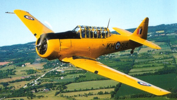
When it took over Noorduyn Aviation in 1946, CCF also acquired the production rights to the North American AT 16 Harvard trainer. Between 1941 and 1945 Noorduyn produced Harvard IIBs as advanced trainers, used to allow those who had become proficient on elementary trainers to graduate to single engined operational aircraft. At the peak of production 83 Harvards per month were leaving the Noorduyn works and by the end of the war 2,800 had been completed, most being used by the RAF and RCAF, but some going as far afield as India, Australia and New Zealand.
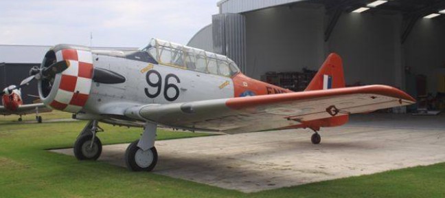
North American Harvard 3*
In 1951, after a gap of six years, the Harvard was again put into production when Can Car’s Fort William plant began to turn out the Harvard 4 to be used in training the pilots who might be needed in the Korean War or its aftermath. In total, 555 were built between 1951 and 1955, initially for the RCAF, but later for the USAF where they were designated T 6J. Some of the T 6Js were subsequently released for service with the West German Air Force.
Harvard 4 / T.6J
The North American Aviation Co. granted rights to the Australians to man¬ufacture the two-seat BC-1, which they called the “Wirraway,” a native word meaning “challenge.” It had twin ma¬chine guns in the nose, a flexible gun in the rear cockpit and could carry up to 500 pounds of bombs on underwing racks. The first Wirraways were rolled out in 1939. They saw heavy service during the first days of World War II as interceptors, fighter-bombers and long-range patrol aircraft, as well as observation craft.
After World War II, the U.S. Air Force changed many of its plane designations, and the “A” was dropped from the Texan’s identification. The T-6s were extremely active during the Korean War as spotter planes. Their pilots were officially known as forward air controllers, but their planes were popularly called “Mosqui¬toes,” since they harassed the Communist forces and specialized in locating enemy targets and guiding fighter-bombers in for airstrikes. They were also flown for air rescues and leaflet-dropping missions. Several were used as interceptors against the North Koreans, who were flying Soviet-made Polikarpov PO-2 night raiders. Numbers of T-6G’s were being converted to LT-6G liaison aircraft by Ternco Corp in 1955. When remanufactured T-6s ar¬rived with improved radios, underwing bomb and smoke-rocket racks and two pod-mounted machine guns, they were designated LT-6Gs. By the end of hostil¬ities, the LT-6Gs had flown more than 40,000 sorties and logged about 117,500 combat hours.
The first Harvard Mk II used by the RCAF was delivered to Camp Borden in the summer of 1940. It was an anglicized version of the AT-6A, the differences being a lengthened exhaust stack, a fixed rear canopy section, an altered instrument panel and a British style control column. The Mk II was also fitted with the capability to hold a .303 calibre air operated machine gun on the starboard wing and a cine-camera in the port wing, with a gun-sight for the front cockpit. The plane was equipped with hardpoints under the wings in order to carry 8 practice bombs. The N.A. Harvard Mk.II was one of the most important single engine training aircraft of the British Commonwealth Air Training Plan. It was known as “the pilot maker” because of its important role in preparing pilots for combat.
After World War 2 the Mk.II Harvard was relegated to armament training and reserve squadron use, as the more modern Mk.IV came along. At the end of WW2, Harvard Mk.II’s were used for Naval training in Nova Scotia. The approval for a Canadian Fleet Air Arm was not given by the government of the day until 1946. In January of 1947 Harvard Mk.II’s began arriving in Dartmouth Nova Scotia for their stint as training aircraft for the newly formed Canadian Naval Air Arm. Much of the training was on gunnery exercises to prepare pilots for the deflection shots necessary with the gyro gun-sight of the Supermarine Seafire. Harvard Mk.II’s were the planes chosen again for the training task. The course was similar to the one used to train RCAF pilots, with the exception of gunnery and formation training which was done on Seafires.
In December 1939, the RNZAF was allocated 105 Harvards, but the first aircraft didn’t arrive until March 1941. The Harvard served in a wide variety of roles with the RNZAF, including flight training schools (2 FTS at Woodbourne being the biggest user), fighter squadrons, fighter operational training units, army co operation squadrons, the Central Flying School and the Fighter Gunnery School. The RNZAF operated Harvard II, IIA, IIB and III as NZ901 to NZ1102 until 1977.
After World War II, T-6s and SNJs were supplied to NATO nations such as France, West Germany, Italy and Bel¬gium. Latin American pilots ferried many of the trainers home after they completed their training in the United States. For use in brush-fire wars, Texans were remanufactured with rocket and bomb racks and designated FT-6Gs. They were sent to such nations as Spain, Por¬tugal, France and Brazil for counterin¬surgency missions.
The Texan was phased out of U.S. Air Force and Navy inventories in 1958, but a number of T-6s were flown by the Civil Air Patrol into the 1960s. Although the American inventory during the Vietnam War showed no T-6s, armed Texans were flown briefly by Laotian and Cambodian pilots against Viet Cong targets along the Ho Chi Minh Trail.
A total of 17,096 of all models were built by North American in California, Texas, Montreal (by Noorduyn), Fort Frances, Ontario (by Canadian Car and Foundry), and in Australia as the Wirraway.
The aircraft is stressed for aerobatics and is capable of most maneuvers with the exception of sustained inverted flight, snap rolls, outside loops, and inverted spins.
The T-6/SNJ/Harvard aircraft have been produced in a number of model designations. Most of the changes are small. Fuel Capacity – The T-6 has 110 gallons on all models except the T-6G and Harvard MK IV, which have 140 gallons. With a cruise fuel burn of 30 GPH, 110 gallons is adequate for most operators. Tail wheel steering/locking systems- The Navy type is lockable only. The pilot is able to lock the tailwheel to a straight-ahead position for take-off and landing. Steering is accomplished by differential braking. The steerable type system (also called P-51 type) uses an inter-connect from the rudder pedals to the tailwheel steering system. This system allows the pilot to steer the aircraft by use of the rudder pedals. Full forward stick movement unlocks this system. When unlocked the tailwheel becomes full swivel and steering is again by differential braking. Either of these systems is adequate for most civilian operators. Hydraulic system – The original system incorporated a pilot controlled bypass. In order to use the gear or flaps, a small button must first be pushed before activation of the system. This button pressurizes the system and a time delay circuit depressurizes the system after approximately 45 seconds. Later aircraft (T6-G/Harvard MK-4) had a modified linkage that engaged the system automatically. For practical purposes, either system is satisfactory. There are several variations in other areas such as instrument panel layout and cockpit glass. Many aircraft have been modified to incorporate various combinations of the above systems.
Harvard II / AT-6C / NA-16-1A / NA-16-3 Span 42 ft (12.8 m) Length 27 ft. 5 3/16 in (8.38 m) Height 8 ft 9 in (2.67 m) Wing area 248 sq. ft (23 sq. m) Weight empty 3,340 lb (1,515 kg) Fuel and oil: 695 lb (315 kg) Armament 141 lb (64 kg) Weight loaded 4,556 lbs (2,065 kg) Wing loading 185 lbs./sq. ft. (90 kg./sq. m) Power loading 8.3 lbs./h.p. (3.71 kg./hp) Speed at sea level 200 m.p.h. (324 kph) Cruising speed at 12,000 ft. (3,660 m.) 185 mph. (298 kph) Landing speed 61 mph (98 kph) Maximum rate of climb 1,800 fpm (590 m/min.) Service ceiling 26,000 ft. (7,930 m.) Cruising range 680 miles (1,102 km)
T 6 / AT-6 Texan / Harvard Engine: Pratt & Whitney Wasp R-1340 AN1, 542 hp Length: 29.003 ft / 8.84 m Height: 11.483 ft / 3.5 m Wingspan: 41.995 ft / 12.8 m Wing area: 252.954 sq.ft / 23.5 sq.m Max take off weight: 5578.7 lb / 2530.0 kg Weight empty: 4101.3 lb / 1860.0 kg Max. weight carried: 1477.4 lb / 670.0 kg Redline speed: 230 mph / 205 kt Max. speed: 181 kt / 335 km/h Initial climb rate: 1358.27 ft/min / 6.9 m/s Service ceiling : 21654 ft / 6600 m Ceiling: 24,200′ Wing load: 22.14 lb/sq.ft / 108.0 kg/sq.m Range: 405 nm / 750 km Endurance: 3 h Crew: 2 Armament: 2 MG Loading: +5.67 / – 2.33G
T-6G Engine: Pratt and Whitney R 1340 AN 1, 550 hp Max speed, 212 mph (341 kph) at 5,000 ft (1524 m) Cruise, 146 mph (235 kph) Initial climb, 1,643 fpm. (8.3 m/sec) Ceiling, 24,750ft (7 544 m) Range, 870 mls (1400 km) Empty weight, 4,271 lb (1937 kg) Loaded weight, 5617 lb (2548 kg) Span, 42 ft 0.25 in (12.8 m) Length 29 ft 6 in (9 m) Wing area 253.7 sq.ft (23.56 sq.m)
Harvard II Engine: P&W R-1340-AN 1 Wasp, 550 hp Span: 42ft (12.8m) Length: 29ft(8.8m) Max wt: 5617 lb (2547kg) Speed: 212mph (341 kph) Range: 870 sm(1400 km).
Harvard IIA Engine: P&W R-1340-AN 1 Wasp, 550 hp.
Noorduyn Harvard Mk IIB Engine: 600 hp Pratt & Whitney Wasp R-1340-AN-1 Maximum speed: 212 mph (341 km/h) Service ceiling: 21,500 ft (6553 m) Empty weight: 4,158 lb (1,886 kg) Loaded weight: 5,617 lb (2,548 kg) Span: 42 ft (12.8 m) Length: 29 ft (8.8 m) Height: 11 ft 8 in (3.5 m) Wing area: 253.7 sq ft (23.6 sq m)
Harvard IIB Engine: P&W R-1340-AN 1 Wasp, 550 hp.
Harvard III Engine: P&W R-1340-AN 1 Wasp, 550 hp.
Harvard IV Engine : Pratt & Whitney R-1340-AN-1, 600 hp Wing Span : 42 ft 4 in Length : 27 ft 11 in Speed : 180 Mph (289 km/h)
Canadian Car and Foundry Harvard IV Engine: Pratt & Whitney R-1340AN-1, 600 HP Propeller: Hamilton Standard Two Blade 12D40 Wing Span: 42′ 5″ Length: 29′ 6″ Height: 11′ 9″ Normal Gross Weight: 5300 lb G Loading: +5.67, -2.33 Controls: Dual Normal cruise: 155 MPH at 8000 ft Fuel flow at cruise: 30 USGPH
Harvard 4 / T.6J Basic trainer Engine: 550 h.p. Pratt & Whitney R1340-ANI Wingspan: 42 ft Length: 29 ft. Loaded weight: 5,617 lb. Max. speed: 212 m.p.h. Ceiling: 21,500 ft. Range: 870 miles at 146 m.p.h. Crew: 2.
SNJ-5 Texan Powerplant: l x Pratt & Whitney R-1340-AN-1 Wasp, 410kW (550 hp) Span: 12.81 m (42ft 0.25 in) Length: 8.99m (29ft 6in) Height: 3.58 m / 11 ft 9 in Wing area: 23.57 sq.m / 253.71 sq ft Armament: 2 or 3 x 7.62-mm (0.3-in) mg Empty weight: 1886 kg / 4158 lb Max T/O weight: 2404 kg (5,300 lb) Max speed: 330 km/h / 205 mph at 5,000 ft Ceiling: 6555 m / 21500 ft Max range: 1200 km / 746 miles Operational range: 750 miles Crew: 2
Developed by General Aviation (the precursor of North American Aviation) to meet a US Army specification for an observation aircraft, the GA-15 represented a radical change in design for such a role in that, unlike its predecessors, it was a low-wing monoplane with an enclosed cockpit, seating a three-man crew.
Powered by a 634kW Wright Cyclone engine, the prototype GA-15 / XO-47 36-145, built at Dundalk MD, flew in mid-1935 and to provide an acceptable field of view for the observer a glazed nose position was located under the fuselage. North American put the type into production to meet a USAAC contract for 109 North American O-47A aircraft ordered in February 1937, later increased to 164. They were powered by 727kW Cyclones, while 74 O-47B aircraft had 790kW engines and additional fuel capacity. During World War II they served as trainers and target tugs.
North American O-47A 37-260
The O-47A model was released for export in 1939 and is known as the NA-25. 164 of the 1937 O-47A (NA-25, NA-60) were built: 37-260 to 37-368 and 38-271 to 38-325.
Seventy-four 1939 O-47B (NA-51) were built: 39-139 to 39-141.
The Texan began life in 1935 as the NA-16, a prototype trainer designed by James H. “Dutch” Kindelberger, president of North American Aviation, Inc. It had two open cockpits and a fixed gear and was powered by a 400-hp engine.
In 1934, the U.S. Army Air Corps had issued specifications for an airplane “to provide a means of command liaison and command reconnaissance for Corps and Divisions, and to provide for the maintenance of the combat flying proficiency of pilots and observers.” Kindelberger and North American worked to secure the contract, and the NA-16 flew for the first time on April 1,1935. The NA-16 was chosen over the competitors’ designs, but before ordering any NA-16s, the Air Corps required North American to enclose the cockpits with a sliding canopy, install streamlined fairings over the wheel struts and add wheel pants.
When the modifications were complete, the Air Corps ordered 42 (36-028 to 36-069) under the company design number NA-19; the Air Corps called it the BT-9 (basic trainer, type 9). The first production model was flown on April 15, 1936.
North American BT-9
The Navy or¬dered 40 (0910-0949) of them after the existing engine was replaced with a 600hp P&W R-1340 version. That 1937 model was designated the NJ-1 (NA-28, N for trainer and J for North American). The last one was temporarily powered with a 1000hp Ranger XV-770 as NJ-2.
North American NJ-1 0947
The 40 BT-9As (NA-19A) armed version for Reserve units that followed introduced a fixed forward gun (with gun camera) and a trainable gun in the rear cockpit. Forty were built in 1936, 36-088 to 36-127.
North American BT-9A
Only small changes were made in the 117 BT-9Bs and 67 BT-9Ds. 117 BT-9B (NA-23) were built in 1937 (37-115 to 37-231) with one modified with new wings and tail as the BT-9D (NA-26) in 1938.
North American BT-9B
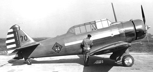
The 1937 BT-9C (NA-29) was an armed version of which sixty-seven were built (37-383 to 37-415). One was modified as the Y1BT-10.
North American BT-9C
One BT-9C, 37-383, was repowered with a 600hp P&W R-1340 in 1938 as the Y1BT-10 (NA-29).
North American Y1BT-10 37-383
The Australian Commonwealth Aircraft Corporation was formed in 1936 by several of the largest industrial concerns in Australia. To gain manufacturing experience, it had been decided to acquire a licence to produce an aircraft suitable for advanced training and as a replacement for RAAF Hawker Demons. An Australian Air Board Technical Commission visited the USA and evaluated the North American NA-16, ordered into production for the USAAC as the BT-9 (NA-19) basic trainer.
At the time of the Australian Commission’s visit, North American was working on a development of the BT-99 with a 600 hp Pratt & Whitney R-1340, retractable undercarriage and armament provision as a basic combat trainer. Designated NA-26, this aircraft fulfilled the Australian requirements, although there was disagreement over the need for retractable undercarriage.
As a result, two versions of the A-26 were offered to the Australians, the NA-32 (NA-16-1A) with fixed undercarriage, and the NA-33 (NA-16-2K) with a retractable undercarriage, and in 1937, negotiations for manufacturing rights in both the NA-32 and NA-33 were completed, and an order placed for one of each.
NA-32 / NA-16-1A
The NA-32 was completed in July 1937, although it was not taken on charge by the RAAF until 8 November 1938, and by that time, the NA-33 / NA-16-2K, which had been completed in September 1937 and taken on charge by the RAAF on 2 February 1938, had already been selected for Australian production.
NA-33 / NA16-2K
The NA-16-2K was with a few subtle changes in design to suit it more closely to RAAF requirements and Australian operating conditions, these including a reinforced sub-structure consistent with the rigors of the bombing role and improved offensive/defensive capabilities by the inclusion of 2 x 7.7mm machine guns as opposed to the NA-16’s sole gun.
With the changes, the NA-33 was ordered into production for the RAAF as the A20, the Commonwealth Aircraft Corporation applying the designation CA-1 to the type, and the name Wirraway being adopted. Production of the initial aircraft was handled out of the Commonwealth Aircraft Corporation (CAC) facility at Fisherman’s Bend in Melbourne, Victoria in 1938.
In 1938, Noorduyn acquired the manufacturing rights to the BT-9.
The basic type was then improved with the flying surfaces of the BC-lA and a metal-covered fuselage to produce the BT-14, of which 251 were built with the 336-kW (450-hp) Pratt & Whitney R-985-25 radial. Some 27 were later converted to BT-14A standard with the 298-kW (400-hp) R-985-11 engine.
Concurrently, the French ordered 230 of the BT-9/BT-14 models and called them Tomcats. When France was overrun by the Germans in 1940, Tomcats not yet delivered were given to the Royal Canadian Air Force and designated Yale Mark Is.
BT-9B Powerplant: l x Wright 8-975-7, 298kW (400 hp) Span: 12.8m (42 ft) Length: 8.41 m (27ft 7in) Armament: 2 x 7.62-mm (0.3-in) mg Max T/O weight: 2028 kg (4,471 lb) Max speed: 170 mph at sea level Operational range: 882 miles Seats: 2
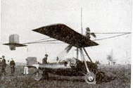
Built in 1930 by designer R.V.Norris of San Franciso, California, the Pendulum plane was to be ‘fool-proof’. It underwent tests at the Redwood City Airport, California, the radial motor is attached to the wing, from which is suspended the fuselage which remains on an even keel during flight. The wing may be tilted in any direction at the will of the pilot, by means of control wires from his seat in the cockpit.