Payne I.C.1

When the Imperial College Gliding Club was formed in February 1930, it had no gliders and therefore decided to build its own. This was designed by J. H. Payne and built by students, with materials donated by the Rector, Sir Henry Tizard. Parts were made in the Chemistry and Glass workshop of the college and the glider was assembled in Payne’s garden.

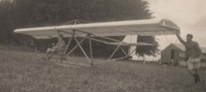
The I.C.1 had a straight, constant chord, thick section wing built around two spruce box spars with plywood webs. The I-section ribs were also made from spruce and ply, the leading edge from ply and the trailing edge form dural. It had outboard ailerons but neither flaps nor airbrakes. The fuselage was an open frame structure with two horizontal, parallel booms that ran rearwards from the wing spars to the tail, where two cross braces carried the tailplane. A pair of N-form struts converged below the wing onto a third boom, horizontal below the wing then angled upwards to the tail, joining the rear cross brace via a short vertical member and two angled ones. The three long booms formed a triangular section girder that did not require further wire bracing.

The pilot’s seat and control column were mounted, unenclosed, on the lower beam ahead on the wing; below him a shallow, curved member served as a keel for landing. The lower beam also provided an attachment point for lift wires, one on each side, to the forward wing spar. Above the wing two further pairs of wires ran from a central, three strut cabane to both spars. The tail surfaces were straight edged and the fin small, its leading edge formed by a sloping member that joined the forward transverse member at the front of the tailplane to the lower fuselage beam. The rudder extended to the lower fuselage.

Named The Incredible, the I.C.1 was completed during the Club’s summer camp at Gore Farm, near Shaftesbury, in September 1930.

During preparation for its first flight, the Incredible was overturned by a gust of wind and damaged. It was stored at Gore Farm and repair work was begun in the 1931 Easter vacation but never completed and the SC.1 never flew. In December 1930 the club had bought a R.F.D. Primary (Dagling), a steel framed version of the German Zogling, which they designated I.C.II and were soon flying regularly.

Wingspan: 36 ft 0 in (10.97 m)
Wing area: 179 sq ft (16.6 m2)
Aspect ratio: 7.2
Airfoil: Probably Bairstow Aerofoil B
Length: 19 ft 5 in (5.92 m)
Height: 7 ft 6 in (2.29 m)
Empty weight: 190 lb (86 kg)
Capacity: 1

Payen PA49 Katy

Designd by Nicolas Roland Payen, Flechair Sa built Payen’s Pa.49 experimental jet-powered delta-winged aircraft. In May 1951, three workers directed by Payen built the all-wood PA-49 in a month. Reportedly named after Roland Payen’s youngest daughter.

It has a triangular shape or Delta wing, 2.7 m swallow tail. The wing has 72 ° sweep, is 11,250 m² with a wingspan of 5.6 m. This wing has no dihedral. The average profile is a modified NACA the 230000 series. The structure of the wing is built in one piece. The trailing edge has flaps in the central part, equipped with tabs controlled in flight. The control surfaces are statically and dynamically balanced. The structure of the wing, is composed mainly of a working chamber, formed by the assembly of two perpendicular rails and oblique side rails symmetrically joined by two ribs. All wing spars or fins, main or joint, and ribs are made of box spruce (laminated strips) and birch plywood.

While the Pa-49’s inboard elevators and outboard ailerons functioned separately, the rudder doubled as a speedbrake.

The Pa-49 strengthened surfaces ‘split’ open to act as air brakes. This solved the problem of interference between the braking and directional controls on an all-wing aircraft.

It is equipped with a Turbomeca Palas turbine engine. The Turbomeca Palas turbojet engine weighed 159 pounds and producied approximately 330 pounds of thrust, it drew air in through dual intakes at the junction of the wing’s leading edge and fuselage.

Originally designed with a bicycle landing gear that incorporated wing-tip skids, the Pa-49 ultimately flew with fixed tricycle gear.

It was not until the end of 1952 and negotiation for the PA-49 to undergo testing in the wind tunnel of ONERA Chalais-Meudon.

First flown on January 22, 1954, by Tony Ochsenbein, the PA49 was the first French delta-wing aircraft.

The endurance of just over one hou was entirely sufficient for short test flights. It was also sufficient for flights to various airshows and industry expositions, where the aircraft was photographed on several occasions, both on static display and in flight.

Between 1954 and the end of 1958, it made many flights before the project became inactive.

Payen Pa-49B Katy

Fortunately, the Katy survived 300 test flights unscathed, and Payen ultimately donated it to the Musée de l’Air et de l’Espace in Paris, where it remains on display today.

Gallery

Engine: one Turbomeca Palas of 330 lb thrust
Wingspan: 16 ft 11 in
Length: 16 ft 8 in
Height: 7 ft 2 in
Empty weights: 1,005 lb
Max all-up weight: 1,430 lb
Maximum speed: 310 mph
Cruise speed: 217 mph
Landing speed: 67 mph
Initial rate of climb: 1,150 ft/min
Ceiling: 27,880 ft
Endurance: just over 1 hr
Accommodation: single-seat

Payen PA-22 / PA-112

Roland Payen evolved a radical tandem-wing configuration which he dubbed the Fléchair, the short-span tapered foreplane carrying a combination of ailerons and flaps and the 67-deg aft plane carrying combined elevator-flaps, the pilot’s cockpit fairing into the vertical tail surfaces. In 1938, Payen proposed to the Ministère de l’Air a lightweight fighter version of the PA 112, a racing aircraft then being developed by the Sociêté Co-operative d’Etudes et Productions Aéronautiques (SCEPA) to the Fléchair configuration and intended to participate in the 1939 Coupe Deutsch de la Meurthe. The PA 112 was to be a retractable monowheel undercarriage with outrigger skids retracting into the aft plane. Weighing only 948 lb (430 kg) empty and 1,345 lb (610 kg) loaded, the PA 112 had extremely small overall dimensions which included a span of 13 ft 7¾ in (4,16 m) and a length of 22 ft 1 in (6,74 m), height being 6 ft 11 in (2,11 m), and it was rather optimistically anticipated that a maximum speed of 360 mph (580 km h) would be attainable. The projected lightweight fighter derivative, the PA112 Cl, was to have had two wing-mounted 7,5-mm machine guns and a 20-mm cannon firing through the extension shafts of the Salmson engines, and an elaborate mock-up of the proposed PA112 Cl was built, this, in fact, utilising the airframe of one of the two PA 100 Coupe Deutsch racing aircraft. Possibly as a result of the dramatically unorthodox nature of the proposed PA 112 Cl, no contract was forthcoming from the Ministère de lAir.

Although no example of the PA 112 was completed and the 1939 Coupe Deutsch was destined never to take place, development of the Fléchair concept continued with the PA 22 which was of similar configuration to the PA 112 but had a conventional engine installation and a conventional fixed tailwheel under¬carriage. The PA 22 had originally been built to test the Mèlot ramjet but was eventually to be completed in 1939 with a 180 hp Régnier R6 inverted inline air-cooled engine. After completion, it was mounted in the Chalais Meudon wind tunnel where it was found by the German occupation forces who expressed some curiosity as to its possible flying characteristics. Accordingly, it was transferred to Villacoublay where it was flown for the first time by Jacques Charpentier in October 1942. A flight test programme was conducted, but before this could be completed, the German authorities decided that the PA 22 should be taken to Rechlin. However, on the pretext that a number of modifications were necessary, Payen succeeded in having the prototype returned to his factory at Juvisy where it was intended to make changes to the undercarriage, mount supplementary fuel tanks and fit a variable-pitch propeller. In the event, these modifications were still in process when the factory was hit during an Allied bombing raid on the Juvisy railway yard, the PA 22 being destroyed.

Engine: Régnier R6 inverted inline air-cooled, 180 hp
Empty weight: 1,221 lb (554 kg)
Loaded weight: 1,894 lb (859 kg)
Wing span: 15 ft 9 in (4,80 m)
Length: 24 ft 3.33 in (7,40 m)
Height: 7 ft 8½ in (2,25 m)
Wing area: 107.64 sq ft (10,00 sq.m)
Maximum speed: 224 mph (360 kmh)
Maximum cruise: 205 mph (330 kmh)
Landing speed: 47 mph (75 kmh)

Payen AP-10

Payen first built a small single-seater AP-10, studied in collaboration with Aubrun. It was a light monoplane with triangular wing with a short length. This machine flew in Dieppe in 1935 and 1936, equipped with an AVA engine of 25 hp, then later a TRAIN of 40 hp. The AP-10 was extrapolated into the two-seater AP-12.

Wing span: 4.95m
Length: 4.16 m
Wing area: 10 sq.m
Empty weight: 200 kg
Max. gross weight: 340 kg
Min. speed: 45 km/h
Max. speed: 200 km/h

Paup P-Craft

Single seat single engined high wing monoplane with two axis control (optional conventional three axis control). Wing has unswept leading edge, swept forward trailing edge and tapering chord; cruciform tail. Pitch control by elevator on tail; yaw control by fin mounted rudder; no separate roll control (optional roll control by ailerons); control inputs through stick for pitch/yaw and (optionally) pedals for roll. Wing braced from below by struts; wing profile; double surface. Undercarriage has three wheels in tail dragger formation; bungee suspension on all wheels. Push right go right tailwheel steering connected to yaw control. No brakes. Aluminium tube/steel tube framework, without pod. Engine mounted below wing driving pusher propeller. Framework in 2024T3 aluminium and 4130 chrome moly steel. Wing covering is Stits Polyfiber, doped.
Shown for the first time to the public at 0shkosh in August 1982, P Craft from D Paup appears to be a minimum aircraft and as such is directly descended from the Kolb Flyer and Ron Wheeler Scout.

This one offers the choice between two axis control, with steering by induced roll, or conventional three axis control when fitted with ailerons (an option on the standard kit). Where the lower longeron and a higher, nearly parallel tube which carries the pilot seat meet at the nose, there is a horizontal transverse tube on which can be hinged the rudder pedals.

Paup aircraft offers the two axis version in kit form, requiring 150 hours for completion, at the price of $3395 in 1983.

Engine: Cuyuna 215D, 20hp at 6000rpm
Propeller diameter and pitch 36 x 12 inch, 0.91 x 0.30 m
No reduction
Power per unit area 0.15hp/sq.ft, 1.6hp/sq.m
Fuel capacity 2.5 US gal, 2.1 Imp gal, 9.5 litre
Wing span 32.5 ft, 9.88 m
Total wing area 132 sq.ft, 12.3 sq.m
Wing aspect ratio 8.0/1
Main wheels diameter overall 20 inch, 51 cm
Empty weight 165 lb, 75kg
Max take off weight 402 lb, 182 kg
Payload 237 lb, 107 kg
Max wing loading 3.05 lb/sq.ft, 14.8 kg/sq.m
Max power loading 20.1 lb/hp, 9.1 kg/hp
Max level speed 60 mph, 97 kph
Never exceed speed 70 mph, 113 kph
Max cruising speed 50 mph, 80 kph
Economic cruising speed 35 mph, 56 kph
Stalling speed 22 mph, 35 kph
Max climb rate at sea level 300ft/min, 1.5m/s
Take off distance 75 ft, 23 m

Paulista CAP-9 Carioca

The Companhia Aeronáutica Paulista CAP-9 Carioca four-seat, single-engine high-wing monoplane with enclosed cockpit and fixed undercarriage, was CAP’s last attempt, in 1947, to remain in the aircraft market. The company had chosen to build the CAP-9 Carioca instead of the CAP-8. The CAP-8 (which reached the prototype stage) was a 4-seater low-wing aircraft and although the prototype was made of wood in order to gain time (the war was about to end but there was still a shortage of aluminum), the idea was to build an all-metal aircraft.

Without commercial success with its new projects and a vertiginous drop in its orders, CAP ends its activities in 1948.