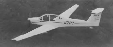
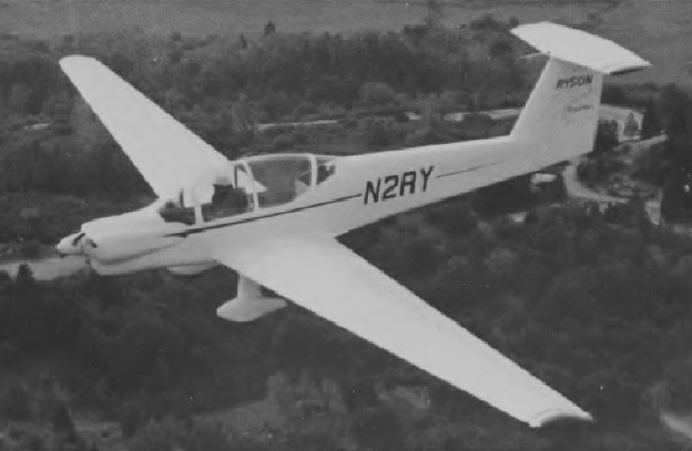
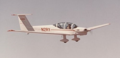
The ST-100 Cloudster tandem two-seater motor glider is believed to be the first American type in this category to be designed for production, and was created by the Ryson Aviation Corporation. A Pazmany designed self launching sailplane called the Cloudster, in mem¬ory of the original flagship of Ryan Airlines. The work Pazmany did designing the Cloudster’s landing gear led him to write the book “Landing Gear Design For Light Aircraft”.
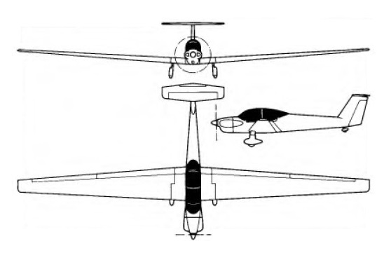
Design work started on 18 March 1974 as a cantilever low-wing monoplane of all-metal construction, with a T-tail, a fixed spatted undercarriage and a conventional engine installation with a Continental O-200, and of all-metal construction. The wings are all-metal safe-life structures, with some fail-safe features, and have a single main spar located at the 40% chord line, the point of maximum thickness, and an auxiliary spar at 80% chord; dihedral is 4°. Both ailerons and trailing edge flaps are of aluminium with a foam core, the flaps being electrically-operated and can be lowered to 72° when used as air brakes; the ailerons, like the flaps, can be raised 12° and they can be drooped 8° in conjunction with the flaps. After that, the flaps continue down to any desired position. No spoilers or trim tabs are fitted, and the wings can be folded back alongside the fuselage, leading edges down, for hangarage or transportation. The fuselage is a semi-monocoque structure with extruded aluminium longerons, and sheet metal frames, bulkheads and skinning. The pilots sit in tandem under a one-piece Plexiglas canopy that opens sideways to starboard; there is baggage space aft of the rear seat, and the rear occupant has flight controls but not an instrument panel, as he can see the instruments over the front pilot’s shoulders. Both seats are designed to accommodate parachutes, and the cockpit is heated and ventilated. The cantilever T-tail has a sweptback fin and rudder, a fixed-incidence tailplane and a one-piece balanced elevator. The rudder and elevator are aluminium-covered, with sheet metal and foam ribs, and the elevator tips can be removed when the aircraft is being transported; the elevator has an anti-servo and trim tab. A conventional fixed tailwheel landing gear is featured, with streamlined glassfibre fairings on the main gear legs, main wheels and tailwheel, which is steerable. The main wheels have Cleveland hydraulic disc brakes and Ryson oleo-pneumatic shock absorbers. Powerplant is a 100hp Continental 0-200-A ‘flat four’ engine driving a two-blade three-position Hoffman HO-V-62 feathering propeller with composite blades. There are two integral fuel tanks in the wing centre section leading edges with a total capacity of 32 US gallons (26.6 Imp gallons.)
Construction of the prototype, registered N2RY, began on 11 July 1974; it made its first flight on 21 December 1976 in the hands of test pilot Ray Cote.
The ST-100 is designed to be aerobatic and to meet the FAR Part 23 gust load requirements. It can also be used as an aero-tow aircraft for unpowered sailplanes. It has towed a Schweizer SGS 1-26 single-seater to 13,000ft with an initial climb rate of 450ft/min and, with two people aboard, it has also towed a Schweizer SGS 2-33 with two occupants at an initial rate of climb of about 400ft/min.
In the summer of 1977 Ray Cote made a notable economy-record flight in the ST-100 from El Mirage, California, to the EAA display at Oshkosh, Wisconsin, covering the 1,676 miles on 28 of the 32 available US gallons of fuel in 18 hours of soaring flight and 13 hours of powered flight. This was followed by a 4,300 mile flight around the perimeter of the United States. Only 20-percent power is required to keep the Cloudster in level flight. As a touring airplane, it cruises at 135 mph (75-percent power) using just 6 gph to yield a range of 690 miles. At lower power settings, the range can be greatly increased.
Production of the ST-100 by a licensee was planned when FAA type certification was awarded.
Engine: Continental O-200, 74.5 kW / 100 hp Span: 57 ft 8 in / 17.58 m Length: 25 ft 6.5 in / 7.78 m Height: 5 ft 10 in / 1.78 m Wingarea: 213.0 sq.ft / 19.79 sq.m Aspect ratio: 15.61 Airfoil: Wortmann FX 67-170/17 Empty weight: 1,212 lb / 550 kg Max weight: 1,650 lb / 748 kg Water ballast: None Max wing loading 7.74 lb/sq ft / 37.8 kg/sq.m Max speed at sea level: 150 mph / 130 kt / 241 km/h Max cruising speed: 135 mph Stalling speed 69 km/h / 37 kt Min sinking speed: 2.93 ft/sec / 0.89 m/sec Best glide ratio: 28:1 T-O run: 570ft / 174m Take-off run to 50ft: 950 ft Max rate of climb at S/L: 895 fpm / 273 m/min Range 595 nm / 1,103 km Range with max fuel: 900 miles
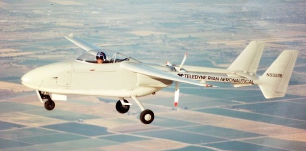
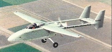
The Teledyne Ryan Model 410 was a surveillance UAV designed in the United States in the late 1980s. In configuration, it was a high-wing cantilever monoplane with twin tails carried on booms and linked by a common horizontal stabilizer. The engine was mounted pusher-fashion at the rear of the fuselage, between the booms. The nosewheel of the tricycle undercarriage was retractable. Construction throughout was of composite materials.
The Model 410 was Ladislao Pazmany’s last design before he quit Ryan. First flying on 27 May 1988, the sole prototype entered its flight test phase at Holtville, Calif, in October 1987. It was converted to manned operation for safety reasons, and completed its manned flight tests early in June 1988. It retained this configuration for the whole of the testing and development phase.
In 1993, the Model 410 was submitted to the UAV Joint Projects Office in response to an RFP for a Tier II system. In January 1994, the contract was awarded to General Atomics for what would eventually become the RQ-1 Predator.
Nothing is known about its fate or current whereabouts of the sole prototype, N53578, but it was deregistered. According to a Northrop Grumman employee, the Model 410 eventually proved overweight.
Powerplant: 1 × Lycoming TIO-320-C1B , 160 hp (120 kW) Wingspan: 31 ft 0 in (9.45 m) Empty weight: 1,450 lb (657.7 kg) Capacity: 300 lb (140 kg) sensor payload carried in internal bay Range: 1,200 mi (1,931.2 km, 1,000 nmi) Endurance: 16 hours
Developed with possible Army operational applications in view, the Ryan VZ 11 uses a totally different concept to obtain VTOL performance. The outcome of several years’ work on lift fans by General Electric Corporation, the VZ 11 derives its vertical lift from two ducted fans, one in each wing.
Unlike other ducted fans, above the General Electric version is powered by the jet exhaust from a turbojet engine which is directed on to turbine blades at the tips of the fan blades.
The VZ 11 layout has two 2,658 lb.s.t. General Electric J85 GE 5 turbojets in the fuselage, fed by a dorsal intake over the two seat cabin. For vertical operations, the fans are powered, together with a third fan in the nose which provides a small lift increment but is primarily for pitch control. For roll control, the thrust developed by the wing fans can be varied differentially by means of ‘butterfly’ doors over the inlets. Louvres under the outlets provide yaw control.
Once the VZ 11 is airborne, the louvres are moved to deflect the fan flow rearwards. This gives the aircraft a forward thrust component. As speed builds up the undercarriage is retracted. At about 120 knots, the wings provide sufficient lift to sustain flight and the exhaust flow from the two engines is then switched from the fans to direct propulsion nozzles. The butterfly doors and louvres close over the fan ducts and the aircraft continues as a conventional jet propelled type.
Two prototypes of the VZ 11 were ordered from Ryan in November 1961 as part of a U.S. Army research contract to investigate lift fans which was placed with General Electric. The designation was changed to VZ-5A in July 1962 and flight trials began in 1963. The XV-5 first flew in May 1964.
Republic Aviation joined GE and Ryan in XV-5A development and was directing flight tests at Edwards AFB in 1964. Republic would share in building additional prototypes if the craft met Army and DoD expectations.
XV-5A Engines: 2 x 1200kg General Electric J85-GE-5 Max take-off weight: 7690 kg / 16954 lb Empty weight: 5450 kg / 12015 lb Wingspan: 9.25 m / 30 ft 4 in Length: 13.75 m / 45 ft 1 in Height: 4.5 m / 15 ft 9 in Max. speed: 880 km/h / 547 mph Ceiling: 12200 m / 40050 ft Range: 1600 km / 994 miles
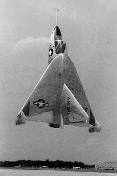
The X-13 was designed to explore the feasibility of building a pure-jet vertical takeoff and landing (VTOL) fighter aircraft. Secondary purposes included validating several Ryan designed VTOL control system concepts.
Ryan produced the X-13 Vertijet and XV-5 VTOL aircraft for the USAF. The X-13 was a ‘tail-sitter in the mould of the Convair XFY-1 and Lockheed XFV-1, though in this instance configured as a pure research type powered by a single 10,000-lb (4536-kg) Rolls-Royce Avon turbojet. The aeroplane first flew in conventional mode with temporary wheeled landing gear on 10 December 1955, and in ‘tail-sitter’ mode during May 1956.
The seat tilted forward 45 degrees to give the pilot a more comfortable position during vertical flight. Many early flights were made with no canopy. As first built, the X-13 had a huge fin, its height nearly as great as the wingspan. This was shortened during later testing.
The success and efficiency of the X-13 flight test program provided a significant amount of data to the designers of subsequent VTOL aircraft designs. The X-13s proved that vertical flight, on jet thrust alone, was both technically feasible and practical. The ease with which the aircraft routinely transitioned from vertical to horizontal attitude, and back again, left little question as to the flexibility and operational utility of such flight modes.
The delta-winged X-13 used a unique landing method, involving a special trailer, a hook and a striped pole. To land the pilot had to approach the trailer’s vertical base board without being able to see it. A pole marked with gradations protruded from the board and the pilot had to use this to judge his ‘altitude’ from the landing wire. In one demonstration at the Pentagon, the X-13 flew from its trailer, crossed the Potomac River, destroyed a rose garden with its thrust and landed in a net. Although this impressed the top brass, further funding was not forthcoming and the project petered out.
The last flight was made on 30 July 1957. Fastest Flight: 483 mph (approx) Highest Flight: 10,000 feet (approx)
Both X-13s survived their test program. The first aircraft is on loan from the National Air and Space Museum to the San Diego Aerospace Museum in California. The second aircraft is on display at the Air Force Museum in Dayton, Ohio.
Engine: 1 x 4540kg Rolls-Royce Avon RA.28-49 turbojet Max take-off weight: 3317 kg / 7313 lb Wingspan: 6.40 m / 21 ft 0 in Length: 7.13 m / 23 ft 5 in Height: 4.60 m / 15 ft 1 in Max. speed: 777 km/h / 483 mph
Ordered by the Army in 1956, the VZ 3 or Ryan Model 92 Vertiplane makes use of the deflected slipstream principle which was first proposed in the U.S. as early as 1921 by Dr. Albert F. Zahm. The principle consists of using a conventional wing and propellers for cruising flight and having large flaps on the wing trailing edge which, when extended, deflect the propeller slipstream down¬ward to obtain vertical lift.
The VZ 3 is basically a high wing monoplane with a 1,000 hp Lycoming T53 L 1 turboshaft engine in the fuselage driving two 9 ft. diameter slow running propellers. The wing tips were turned down to prevent spanwise flow and power loss when the flaps were down. For control at low, speeds, engine exhaust was directed to a swivel nozzle at the end of the fuselage, giving pitch and yaw control; roll control came from differential pitch applied to the propellers.
Ryan test pilot Peter Girard made the first taxying trials of the VZ 3 (56 6941) on February 7th, 1958.
Subsequently, it spent three months in the full scale low speed wind tunnel at the N.A.S.A. Ames Laboratory at Moffet Field. At this stage it had a tail down undercarriage, but a nosewheel was added, as well as a large ventral fin, before the first flight was made on January 21st, 1959, at Moffet Field.
On the thirteenth test flight, on February 13th, 1959, the VZ 3 was damaged in a landing mishap caused by a malfunction in the propeller control system. Trials were resumed later in the summer and Ryan completed a test programme in which a speed range of 110 knots to 26 knots was covered, and flights were made up to 5,500 ft. For this second series of trials the cockpit canopy was removed.
In February 1960, after being handed over to NASA, the VZ 3 was almost completely de¬stroyed on a pilot familiarization flight. Operating outside the approved envelope for safe flight, it pitched up and completed most of a loop at 5,000 ft. The pilot ejected safely at 1,000 ft.
After it crashed in 1960 the VZ-3RY was rebuilt with lengthened nosewheel strut, 9 degree lower thrust axis and the LW-1 lightweight ejection seat. Utilising a deflected slipstream principle, the 785 shp Lycoming T53-L-1 turbine, located centrally in the fuselage, drives two wing-mounted Hartzell 3-bladed wood props whose slipstream covers the full wing span. For V/STOL and hover, double wing flaps are fully extended; for transition to horizontal flights, flaps are retracted as the plane picks up speed and the slipstream then flows horizontally.
70 degrees level flight with full flap, 29 mph
Conventional stick and rudder pedals controls actuate rudder, elevator, variable-incidence T-tailplane, and spoilers in the upper wing forward of the flaps, these replace the usual ailerons. Large wing tip end-plates provide structural support for the flaps and confine the slipstream.
Gas turbine tailpipe nozzles deflect Jetstream at right angles to eliminate forward thrust. Pitch and yaw control is achieved by shielding one side of the nozzle. For roll control ailerons actuate prop pitch control differentially when flaps are extended.
After a complete rebuild, the VZ 3 was returned to NASA in 1961 and pilots Fred Drinkwater and Bob Innis began a programme to investigate its low speed handling characteristics. Several modifications were made at this time, since when the VZ 3 has been contributing valuable data for the development of other VTOL aeroplanes.
Engine: 1 x 785 shp Lycoming T53-L-1 Props: 2 x Hartzell 3-bladed wood Span: 23 ft 5 in Length: 27 ft 8 in Height: 10 ft 8 in Gross weight: 2925 lb
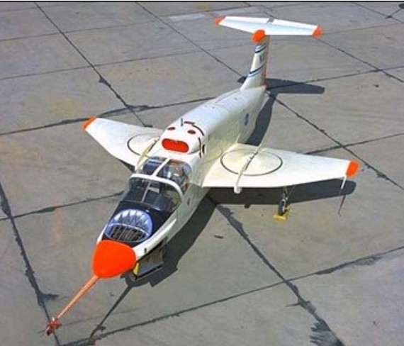
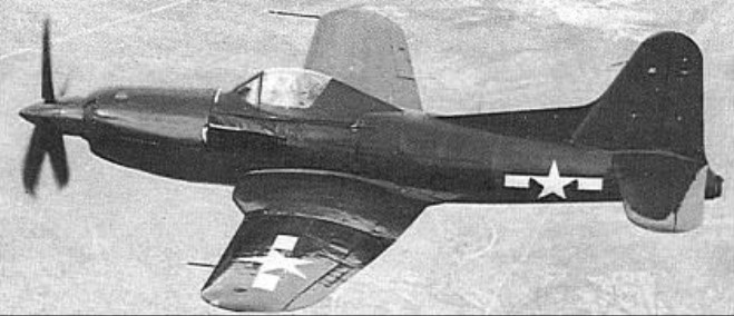
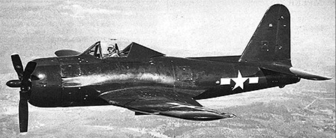
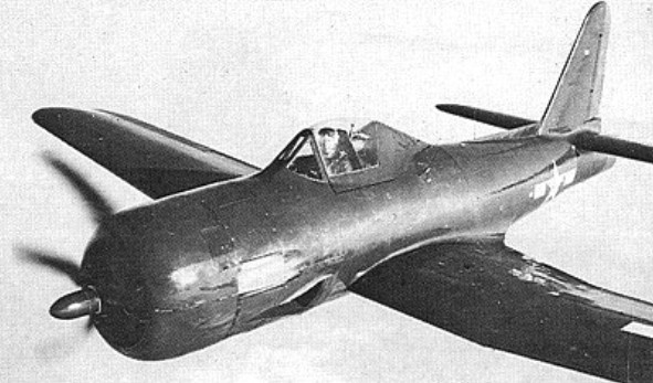
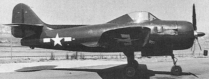
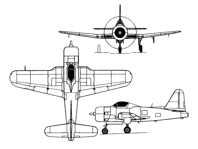
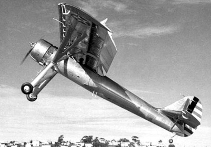
A major modification of the FR-1 Fireball, the Model 29 resulted from a Bureau of Aeronautics requirement for a single-seat fighter combining a turboprop with a turbojet. Assigned the designation XF2R-1 and later to become known unofficially as the “Dark Shark”, the single prototype utilised the fifteenth FR-1 production airframe and retained that fighter’s J31-GE-3 turbojet, mated with a General Electric XT31-GE-2 turboprop developing 1,700hp plus 227kg of residual thrust.
Although lacking the wing folding and the catapult and arrester gear standard on the FR-1, the XF2R-1 weighed 473kg more than its predecessor when it flew for the first time in November 1946. The XT31 drove a propeller with four square-tipped hollow-steel blades which could be fully feathered or reversed to zero blade angle extremely rapidly, the drag of the flatter blade angle serving as an effective air brake for landing. By comparison with the FR-1, the vertical tail surfaces of the XF2R-1 were enlarged to compensate for the lengthening forward to accommodate the turboprop, but the airframe of the later fighter was similar in most other respects. The XF2R-1 underwent extensive testing at Muroc Dry Lake, but no further development was undertaken.
Max take-off weight: 4990 kg / 11001 lb Wingspan: 12.80 m / 42 ft 0 in Length: 10.97 m / 36 ft 0 in Height: 4.27 m / 14 ft 0 in Wing area: 28.33 sq.m / 304.94 sq ft Max. speed: 800 km/h / 497 mph Ceiling: 11920 m / 39100 ft
In December 1942, nine US aircraft manufacturers received a Request for Proposals from the Bureau of Aeronautics for a single-seat shipboard fighter combining piston engine and turbojet, the former to be the main power source and the latter to provide boost in climb and combat. The Ryan Model 28, designed by Benjamin T Salmon and William T Immenschuh, was selected as winning contender by the Bureau and three prototypes were ordered on 11 February 1943 as XFR-1s.
A low-wing, cantilever monoplane of classic design, the XFR-1 was the first carrier aircraft designed from the outset to use a laminar-flow aerofoil and the first US Navy aircraft to have an entirely flush-riveted exterior and metal-skinned movable control surfaces. Power was provided by a 1,350hp Wright R-1820-72W Cyclone nine-cylinder air-cooled radial and, in the rear fuselage, a 726kg General Electric I-16 (later redesignated J31) turbojet. Proposed armament consisted of four 12.7mm machine guns with provision for a 454kg bomb under port inboard wing panel. Other features were hydraulically-folding outer wings and a tricycle undercarriage.
A contract for 100 production FR-1s was placed on 2 December 1943, the first XFR-1 flying seven months later, on 25 June 1944, with only the piston engine installed. The turbojet was added a few days later. Initial flight tests led to the major redesign and enlargement of the vertical tail and lowering of the horizontal tail. On 31 January 1945, by which time a number of series FR-1s had been completed and were under test, a contract was placed for 600 FR-2s which were to differ in having the R-1820- 74W engine of 1,500hp with water injection. In the event, neither the FR-2 nor the XFR-3 was to be built, the latter being intended to mate the 907kg General Electric I-20 turbojet with the -74W piston engine.
XFR-4
The XFR-4 entered flight test in November 1944. Utilising the 19th FR-1 production airframe, this replaced the J31-GE-3 turbojet with a 1542kg Westinghouse J34-WE-22, discarded the wing root intakes of the FR-1 in favour of flush inlets in the sides of the forward fuselage, and had the aft fuselage extended by 20cm. It was found, however, that the thrust of the J34 was too great to permit efficient use of both engines and the XFR-4 programme was discontinued accordingly.
Due to its (relatively) high-speed dash capability, the Fireball was considered for use in defence against kamikaze attacks. The war ended just as the first squadron was becoming operational. .Deliveries of the FR-1 to the US Navy began in March 1945, the Fireballs equipping one squadron (VF-66) and completing carrier qualification in May (aboard the USS Ranger). After VJ-Day, the 34 FR-1s remaining to be delivered were cancelled, together with all 600 FR-2s. On 18 October 1945, VF-66 was de-commissioned and its FR-1s transferred to VF-41 (redesignated VF-1E on 15 November 1946) which continued to fly them until mid- July 1947. Only 17 of the 66 FR-1s built saw squadron usage, the remainder being assigned for various test programmes.
FR-1 Engines: 1 x GE J31-GE-3 turbojet, 1600 lbs (726 kg) thrust & 1 x Wright Cyclone R1820-72W, 1425 hp piston. Wingspan: 12.19 m / 40 ft 0 in Length: 9.85 m / 32 ft 4 in Height: 4.24 m / 14 ft 11 in Wing area: 25.54 sq.m / 274.91 sq ft Max take-off weight: 5285 kg / 11651 lb Empty weight: 3488 kg / 7690 lb Max speed: 370 kts, (piston power only: 255 kts). Range: 1658 km / 1030 miles
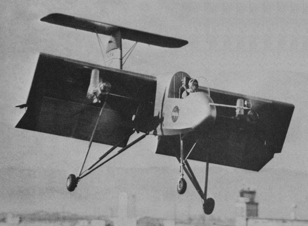
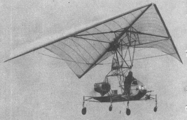
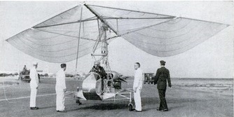
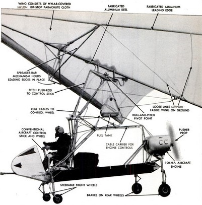
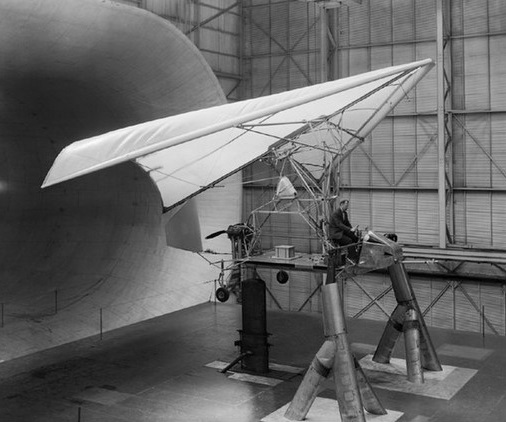
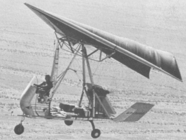
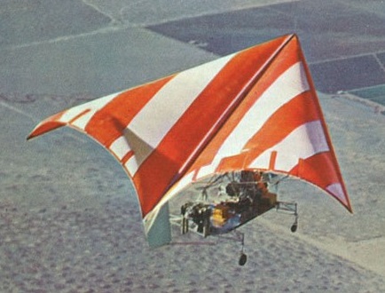
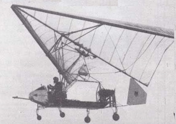
The XV-8A aircraft (designated FLEEP) resulted from Ryan Aeronautical Company design studies of the application of the Rogallo flexible-wing concept to a manned aircraft. This aircraft is an improved version of the origional Ryan flexible-wing manned test vehicle. The aircraft was designed as a single-place, lightweight utility vehicle, capableof carrying a 1000-pound payload and having short-field take-off and landing characteristics.
The US Army Precision Drop Glider was designed and constructed by the Ryan Aeronautical Co. Cecil Craigo was the program manager. This cargo delivery system was designed for a payload of 300 pounds which is contained in a rectangular box attached to the bottom of the wing control platform. Four riser straps are attached to the sides of the control platform and the suspension lines from the wing are attached to the risers.
The XV-8A was a delta-shaped, fabric Rogallo wing with inflatable leading edge, attached to a podlike cockpit on a tri-gear platform; V-tail. It folded into a relatively small package for transport. It was nicknamed “Fleep,” short for “Flying Jeep.”
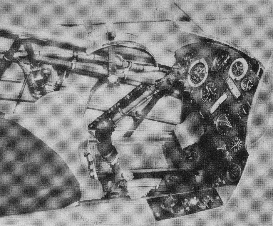
The basic body structure was in the form of a flat deck. A raised platform at the forward end supports the pilot’s seat, nose wheel, control mechanism, instrument panel, and nose fairing. Fittings on the pilot’s seat back and at the sides of the platform attach the wing support struts. Other fittings at the aft end of the platform provide attachment for the engine mount truss and tail surfaces. The useable cargo area, 64 inches wide and 80 inches long, is fitted with twelve standard flush-type cargo tie-down rings. Because of the open-deck design, long slender cargo items may extend both forward and aft of the normal cargo area. Riveted aluminum alloy sheet and extruded sections are utilized in fabricating the platform structure. Jacking pads are provided on the lower surface of the platform at the main landing gear and at the forward end of the cargo area. The forward end of the pilot’s cockpit is a removable fiberglass fairing. The fairing support framework also supports the instrument panel and the transparent plastic windshield. The pilot’s seat, an integral part of the vehicle structure, is equipped with a standard seat belt and shoulder harness. Space has been provided to accommodate a back-pack type parachute.
The wing is composed of three main structural members: a rigid center keel, and rigid right and left leading edges. The two leading edges join the keel at the apex and form a near-triangular wing planform. The keel runs longitudinally aft from the apex along the center line of the wing. The flexible membrane, made of Dacron with a polyester coating, is continuously attached to the leading edges and keel. The leading edges have a 50-degree sweep angle. The total wing area in flat planform is 450 square feet.
The wing had 6-inch-diameter inflated-tube leading edges and keel, which are 22 feet long and a cloth lifting surface. Air for inflating the leading edges and keel is supplied by a high-pressure storage bottle in the rear of the keel. Directional control is achieved by pulling on the suspension line on either wing tip and is actuated by a motor in the control platform. The control system was designed for steering by radio command from a ground or air controller, or by an automatic homing system that seeks a radio beacon located on the ground in the target drop area.
The wing is of the foldable flexible type made up of a rigid keel, two rigid leading edges, a rigid spreader bar, flexible membrane, fittings, and attaching hardware. The forward ends of the leading edges attach to the forward end of the keel to form an apex which sweepsback at a 50 degree angle. The spreader bar which attaches to the keel at about midway, supports the leading edges to produce the proper sweepangle, and transmits the leading edge lift loads to the keel. The wing keel is a tapered sheet aluminum alloy boxtype structure. A fitting at its forward end supports the leading edge members. The keel attaches to the spreader bar by a hinge fitting at the keel 46 percent station. Fittings are provided forward and aft of the main hinge to attach the pitch trim control cables. The leading edges are hollow aluminum alloy spars which have a symmetrical streamlined cross section, and taper from a maximum cross section near the spreader bar attachment toward both ends. An aluminum alloy channel at the maximum cross section serves as a shear web. The attachment at the spreader bar is a swivel fitting with one axis lying along a chord-line and the other axis forward of and parallel to the leading edge. The attachment at the keel is aspherical rod end type fitting. Since the spar is free to align itself to the load, and the wing membrane is attached along the trailing edge, membrane tension is always applied to the plane of maximum spar stiffness. The aft 13-1/2 percent of the leading edge is hinged to permit a 5 degree motion in a chordwise direction to provide additional lateral control. The hinge mechanism incorporates linkage to multiply the mechanical advantage of the actuating cable used to control the position of the hinged leading edge portion in flight.
The original wing was nylon sealed with Mylar but this was replaced with Dacron cloth sealed with a resin as the Dacron was more durable in sunlight. The wing membrane fabric is square weave Dacron cloth coated on both sides with olive drab polyester resin. The coated material is flexible and extremely weather resistant. Total weight of the coated fabric is 8 ounces per square yard. The coated fabric has a tensile strength of not less than 200 pounds per inch in the warp direction, and not less than 120 pounds per inch in the fill direction. The membrane is attached along the keel and leading edges with machine screws. Metal reinforcing strips are bonded into the reinforced, bonded, and sewn edges of the membrane. To prevent trailing edge flutter, the aft edge of the membrane is scalloped, and thin wooden battens (3 per lobe) are retained in pockets sewn in the trailing edge membrane. A reinforcing cable, the length of which is adjustable on the ground for roll trim, is sewn into a hem along the aft edge of the membrane.
The wing is folded in a compact package similar to a parachute pack and was located in the control platform before deployment. The cargo box and packaged wing are discharged from an aircraft and wing deployment is initiated by a static line. Deployment loads are attenuated by use of an initial parachute like phase. After the tubes have been inflated the reefing lines are cut, and the wing completes deployment and then makes a transition from vertical flight to gliding flight.
The landing gear is of the tricycle type. The nose and main tires and wheels are the same size and type to minimize spare part requirements. The main landing gear tread is 9.0 feet, and the wheel-base is 10.63 feet. Large, low-pressure type III tires aid operation from soft ground or rough fields. Landing loads at the main wheels are absorbed by cantilever Fiberglas springs extending from both sides of the platform structure. Heat treated steel axles which mount the aluminum alloy wheels are bolted and clamped to the outboard ends of the springs. Single disc type hydraulic brakes incorporated in the main wheels are hydraulically actuated by a master cylinder in the pilot’s cockpit. Pressurized hydraulic fluid is supplied to the brakes through flexible hoses encased in wire braid. An oleo strut type shock absorber is incorporated in the nose landing gear. The nose landing gear assembly attaches to the forward end of the sheet metal platform by a tubular tripod type structure. The nose wheel which can be steered through an angle of 25 degrees either side of center by operating foot pedals in the pilot’s cockpit produces a turning radius of 27.83 feet. The foot pedals are connected to arms extending from the sides of the shock absorber piston tube by a simple cable and pulley system. The nose wheel is aligned in a fore and aft position in flight by a centering cam.
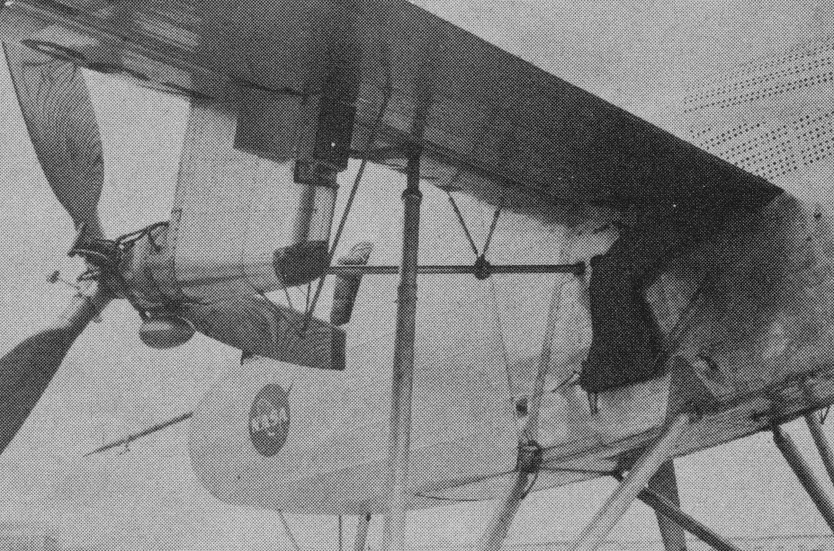
The propulsion system consisted of a six cylinder, aircraft reciprocating engine equipped with a fixed-pitch propeller employed as a pusher, and an exhaust-driven ejector cooling system. A steel tube truss supported the engine near the aft end of the platform structure. Four flexible rubber mounts are used to attach the engine to the truss. The propeller thrust line is inclined 3 degrees up at the rear with respect to the platform surface. The exhaust driven ejector cooling system is self-regulating, and requires no action on the part of the pilot. Sheet aluminum baffles direct the cooling air through cooling fins on the engine cylinders and heads.
A pilot’s seat and the necessary flight controls are provided at the forward end of the platform. An engine, pusher propeller, and a V-tail are mounted at the rear of the platform. Provision is made for manually folding the wing and tail surfaces. A rudder was also added to provide better control in crosswinds and the original engine was replaced with a larger 185 hp engine.
A full scale of XV-8A Fleep prototype, a flexible wing aircraft built by Ryan, was flown in NASA Langley Research Center’s Full Scale Tunnel. The Ryan testbed was not a prototype for a production aircraft. It was for research alone, hence all its cables and linkages were exposed. Adjustmenst could be made without opening panels.
This program was successful in demonstrating the feasibility of aerial delivery of cargo by means of a deployable parawing. It was anticipated that development of this use for a parawing would continue and additional controls can be included to provide flare capability for reduction of landing speeds.
The performance capabilities of the airplane were all within predicted values. The cruise capability was such that a 100-mile mission can be flown at maximum gross weight. Take-off and landing performance proved the STOL capability of the airplane. At maximum gross weight, the take-off distance over a 50-foot obstacle is 1,000 feet. Landing distance to clear a 50-foot obstacle is 400 feet. During the course of the test program, the airplane proved to be a reliable and easy aircraft to maintain and service. Some test operations were conducted from unprepared desert surfaces, establishing the capability for operation from areas other than regular airfields. The operational and flying techniques are basically similar to those of lightweight conventional aircraft. The two-control system lends itself to simplicity and provides adequate control power to permit a fixed wing incidence trim setting for the entire flight including take-off, climb, cruise, descent, and landing.
XV-8A Fleep
The handling characteristics of the aircraft were good. Control harmony between the longitudinal and lateral control systems was excellent, enabling the aircraft to be flown with one hand. Stability in all cases was positive with only light forces required. The flight characteristics of this airplane were similar in most respects to those found in a conventional airplane with a comparable light wing loading.
The aircraft was safe and pleasant to fly for an Army pilot of average skill. In flight the craft got light at 30 mph for takeoff and the platform remained level during climb and turns. Occasionally the platform rocked gently back and forth or from side to side in gusty air, yet the cloth remained completely stable. Data available indicated that, with improvements, the concept can be developed into a flying truck with reduced experience and skill requirements for the operator. Helicopter and light plane experience aids in transition to this aircraft, although such experience was by no means necessary. The aircraft is capable of rough field operation with certain advantages over fixed-wing aircraft or helicopters.
Safe landing characteristics with engine power at idle were demonstrated. The system was highly sensitive to turbulence and rough air which is uncomfortable, but is self-damping to a high degree. The wing appeared to lose lift in some conditions of turbulence, causing some degradation of climb and descent performance. Crosswind operation investigations were continuously conducted. The results suggested that limitations will eventually be established that were quite compatible with light aircraft of about the same weight.
The idea of a primitive, low-cost, low-maintenance, limited-performance but useful aerial device was clearly demonstrated. For example, only one operation out of 47 was delayed due to aircraft maintenance. This program did not represent an operational evaluation environment; however, the low maintenance and support required was very unusual for an experimental aircraft. The aircraft met or exceeded all predicted performance goals and demonstrated its ability to haul bulky cargo shapes and a useful load almost equal to its empty weight. The ability of the aircraft to operate as a light STOL utility vehicle with a 100-mile range was established.
The YO-51 Dragonfly of 1940 was observation monoplane built for the USAAC.
Engine: 1 x 440hp Pratt and Whitney R-985-21 Wasp Junior Max take-off weight: 1908 kg / 4206 lb Wingspan: 15.85 m / 52 ft 0 in Length: 10.51 m / 35 ft 6 in Max. speed: 208 km/h / 129 mph Cruise speed: 172 km/h / 107 mph Crew: 2