Slingsby Hjordis

The Hjordis, named after the heroine of a Norse saga, was designed by Sqn Ldr Mungo Buxton of the Royal Air
Force. Buxton, in partnership with Philip Wills, placed the order for its construction with Slingsby in 1934, but for some reason it never acquired a Slingsby type number. The drawings supplied by Buxton showed all the main features of the proposed aircraft, but most of the details remained to be worked out. A good deal was evidently done in the workshops and never fully committed to paper. Only one of the type was built.

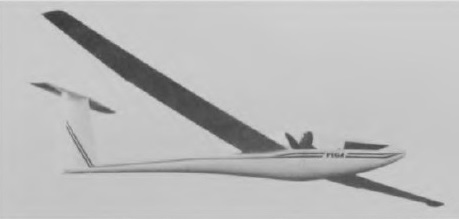
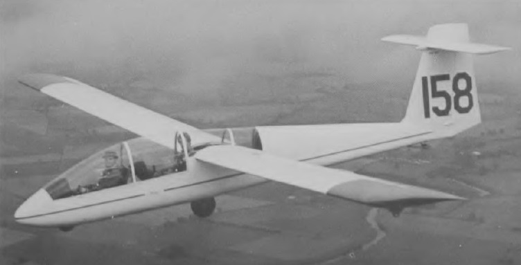
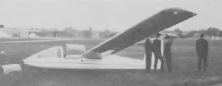
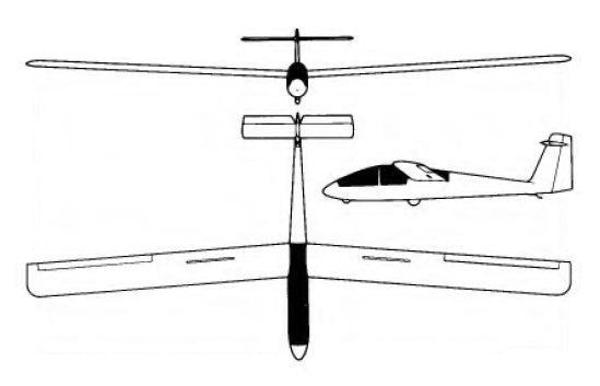
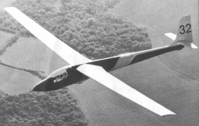
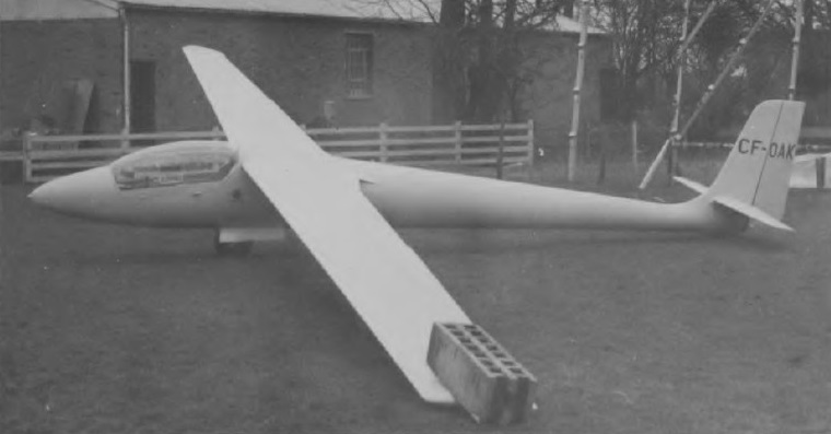
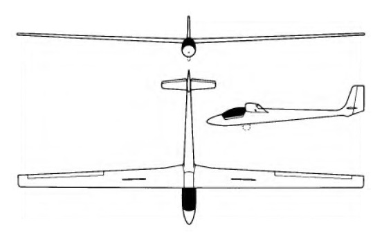
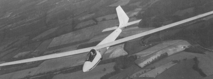
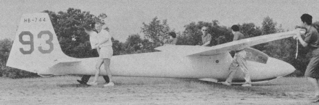
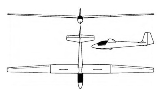
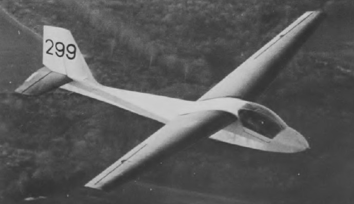
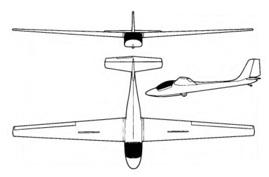
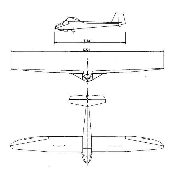
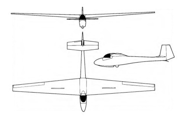
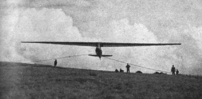
The Hjordis had a cantilever wing of unusually high aspect ratio, strongly cambered and very thick at the root, mounted on a very tall, narrow pylon above the fuselage. Spanning just over 15.5m (51ft) the wing had a slight anhedral angle. Viewed from the front, the undersurface of the wing was flat from tip to tip. The taper in thickness resulted in the upper side of the wing descending. This unusual feature was never explained by Buxton, but he may have thought it would improve response to the lateral controls. There was a small
wheel on the control column instead of the familiar stick to operate the ailerons, as there was insufficient room to move a joystick laterally.

Buxton had in mind the needs of private-owner syndicates who would operate with minimal crew. He aimed to achieve the best possible soaring performance with a relatively modest wing span. A tapered planform was necessary, both to cut tip vortex drag and to ensure adequate depth of spar to accommodate bending loads at the inner end of the cantilever wing. The taper of the Hjordis wing was fairly pronounced, the ratio being about 4:1.

On the Rhonadler, large amounts of negative wing twist or ‘washout’ were used to ensure that the tips did not stall early. Hjordis incorporated similar ideas.

The choice of the thick, strongly cambered Gottingen 652 section for the wing root of Hjordis was influenced by the successes of the famous Fafnir sailplane designed by Alexander Lippisch, The section at the mid semi-span position was one Buxton s own devising, thinner and less strongly cambered than Go 652. From this position the profile changed gradually to RAF.32 at the extreme tips. The layout was cleverly devised so that, geometrically,
the base lines from which the various profiles were plotted remained in alignment, Buxton pointed out that the wing could be built on a flat bench. Each rib would touch the flat surface at two points and would automatically be at the required rigging angle, no complicated blocking up or jigging being needed. Because of the gradual variation of camber and thickness there was 6° of aerodynamic washout, although geometrically there appeared to be none. This stratagem was entirely successful, and tip stalling was never a problem with Hjordis. It was found impossible to make the sailplane spin.

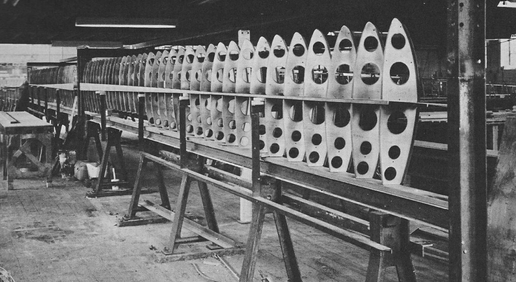
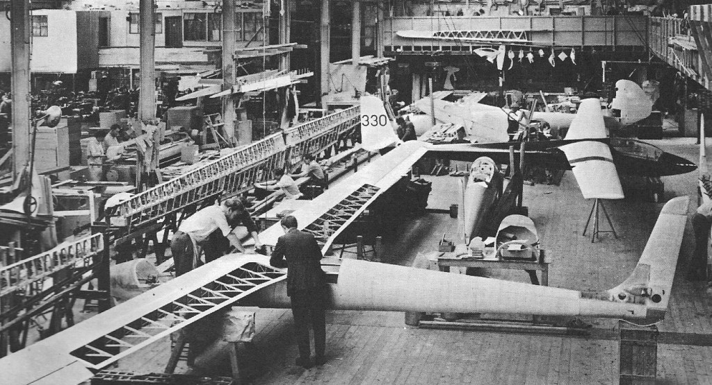
The main wing spar was necessarily massive, the flanges laminated in spruce with plywood shear webbing and hefty steel fittings with horizontal pins to attach the wings separately to the fuselage pylon. A lighter rear spar carried the ailerons. The ribs, with narrow spruce booms and substantial plywood webs to stiffen them, were spaced at a pitch of 8in (203mm). This was less than usual, but obviated the need for intermediate sub-ribs ahead of the main spar. The most unusual feature of the wing was that it was covered with plywood back to the auxiliary spar, when the usual practice at this time was to use ply skin only around the leading edge and cover the rest with doped fabric. The advantages of the extended stressed skin were that the aerofoil section was more accurately preserved and the wing was very much stiffer in torsion.

The total weight of the aircraft was considerably increased, and unlike most sailplanes of the period the plywood covered areas were painted, which added a few more pounds. The colour was light grey, or turquoise grey according to some accounts, rather than white.

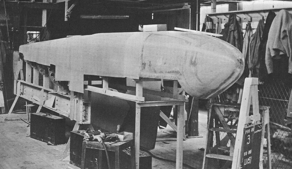
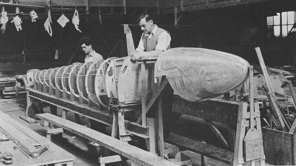
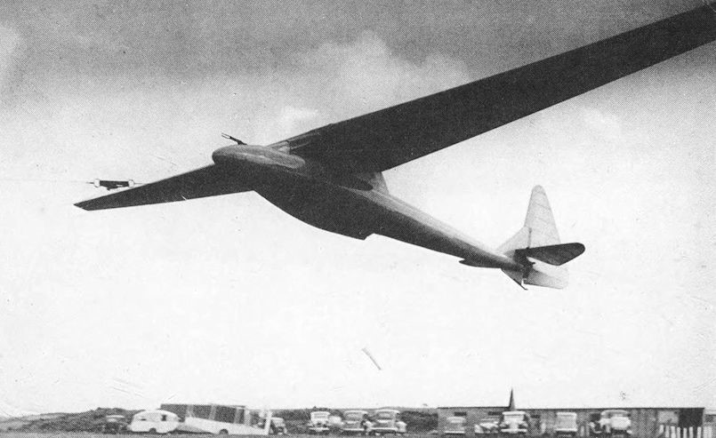
The fabric covered areas were clear doped and varnished, which was orthodox practice. After assembly, the gap between the wings was closed with a light plywood fairing. The fuselage was a nearly perfect cigar shape with only slight downward droop of the form near the nose. The usual semi-monocoque structure was employed, with four main longerons supported by circular crossframes and a complete plywood skin. The tall pylon was based on two very robust vertical spars connecting the wing fittings directly to the main skid attachments.

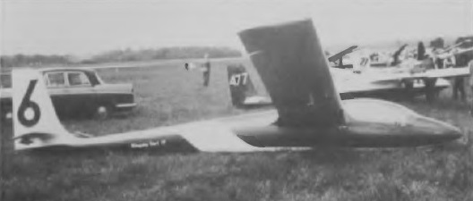
Buxton had seen various types of accidents to sailplanes with pylon-mounted wings. In some cases, when a tip dragged on the ground during a landing, the wing could twist completely off the fuselage. In a touchdown with a little sideways drift, the fuselage might be torn off and rolled under the wing. Minor errors of judgement could thus become bad accidents. The Hjordis pylon was stressed to withstand a side load of half a tonne applied at the skid, and 50kg (110lb) dragging force applied at the wingtip. The tailplane was of the all-moving type, mounted part way up the triangular fin. Hjordis had a large rudder with only a little aerodynamic balancing.

After the end of the 1935 BGA meeting, the editor of Sailplane and Glider reported that the new sailplane ‘seems to have a simply phenomenal performance’. Wills carried off the de Havilland Cup for height gain and the Manio Cup for a pre-declared out and return cross country flight of 38km (23.5 miles).

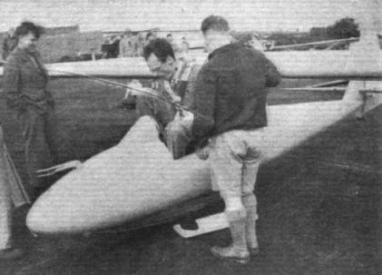
The wing itself, though torsionally stiff, was too flexiblein bending near the tips. After landing, a sailplane tilts over until the wingtip on one side touches the ground. The flexibility of the outer spars allowed the underside to be pressed down on to the surface for some distance, so any stones readily punctured the thin skin. Re- skinning with heavier plywood was necessary. Philip Wills wrote: ‘Quite soon it became apparent that designers have paid too much attention to aerodynamic form and far too little to the shape of the human behind and the needs of the human frame’. He was giving an account of the flight he made in July 1936, which, unpleasant though it was for him, broke the British distance record, 167km (103.5 miles) from Dunstable to the coast south of Lowest oft. The sun beating into the cockpit through the minute talc roof soon gave me a splitting headache. Constant circling and hard work rapidly transformed this into a sick headache. Then came a thirst like the Sahara, closely followed by cramp.’ Relief came only when he ‘burst thickly out of Hjordis’ and sensed ‘the fresh, cool smell of the sea.’ Additional vents were cut. The cramps were reduced a little by chopping out half-moon shaped pieces on either side of the canopy. From this time Wills flew Hjordis with his shoulders sticking out into the breeze.

Buxton himself admitted that the controls were not good. The elevator was too sensitive, and without a trim tab at high speeds the load on the stick was too great. The ailerons were also unsatisfactory. They lacked diagonal stiffeners and so deflected several degrees at the ends under load, giving poor control. The fin was too small. More directional stability was needed.

Probably most serious of all, the Hjordis had no spoilers or airbrakes. Philip Wills was beginning at this time, as he put it, to nibble nervously at clouds, and he had fitted some gyro instruments. On his first serious attempt to circle up blind inside a cumulus, at an Easter meeting in Derbyshire, he lost control within a minute or two. The airspeed indicator went twice round the dial and he ‘burst out of the cloud base in a dive rather over the vertical’ with the Hjordis ‘bellowing like a bull in considerable pain’. The sailplane did not break up, probably owing to the good torsional resistance of the plywood skinned wings.

It had originally been intended to fit an airbrake. The idea was to make the rudder in two pieces, split like a clamshell along the hinge line. When right or left rudder was applied in the normal way, the two clamshells would move together to the same side. To brake, both of the pilot’s feet would be pushed forward and the two shell halves would open out in opposite senses to create high drag. This rudder brake was never fitted. Buxton wrote that among so many new developments this seemed just one too much.

Apart from the dangers of cloud flying without airbrakes, it was a pity that the Hjordis was without even elementary spoilers for landing. Wills damaged it many times because there was no reliable way of getting safely down within a reasonable space. Sideslipping, turning the entire fuselage at an angle to the airflow, could help during the early phases of a landing approach, but the wings had to be levelled well before touchdown. Skimming a few feet off the ground, some extra drag could be created by fishtailing; using the rudder to yaw the aircraft from side to side. This also had to stop before landing. On levelling out and straightening up to flare-out, just when high drag was needed, it was reduced because of the proximity of the ground and its restraining effects on the induced down wash. After a cross-country flight Hjordis would float and float and float across a small field until it hit the upwind boundary or until the pilot deliberately ground-looped to prevent hitting it. In one landing Wills turned it over completely. Buxton mentioned another accident which broke one wing in two and severely twisted the pylon. Only his strong vertical members prevented the glider wringing its neck. There were many other occasions when it had to go back to Slingsby for repairs.

Despite the limitations of his aircraft, Wills had many successes. He captured national records for height gain as well as distance. In the 1936 BGA competitions at Camphill in the Peak District he won the cross-country flying prize, reaching Lincoln. It was not customary at this time to total up the scores and declare a National Champion. Separate prizes were awarded for slope soaring duration flights and gains of height as readily as for distance. It was recognised, nonetheless, that Wills and Hjordis were an outstandingly good combination.

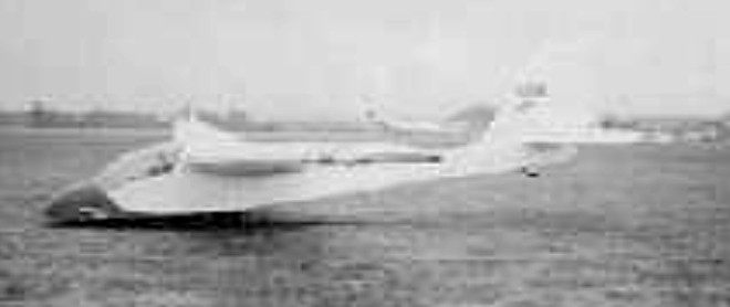
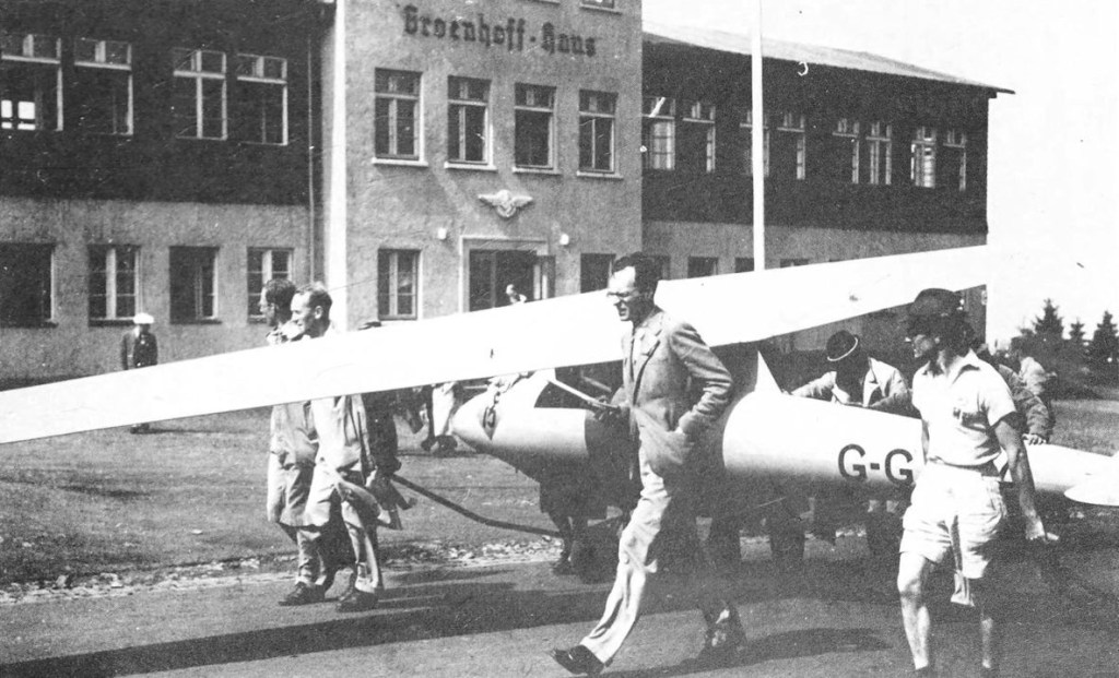
The first truly international soaring championships were held in Germany during July 1937. Five British sailplanes were entered. Wills preferred to take Hjordis, with which by now he was thoroughly familiar, rather than one of the new and, as it proved, unreliable King Kites. Wills placed 14th, exactly halfway down the list. He had his usual problems on landing, ending one flight with the sailplane’s nose in a stream but he and the rest of the British group learned a great deal by observing how the more experienced German and Polish pilots flew. Doubts about the thermal soaring capabilities of their large aircraft were entirely dispersed.

Advertisements appearing in Sailplane and Glider early in 1938 stated:
For sale, HJORDIS, the outstanding British high efficiency sailplane. It holds the British distance and goal flight record, placed first in the 1937 British competitions; holds most of the British Gliding trophies and awards. It has done over 850 miles of cross-country flying (on purpose), has been dived to 125mph in cloud (by accident), is extremely strong (by gum); won the distance trophy (by Wakefield); is in first class condition (by Slingsby); and is for sale by Philip Wills.

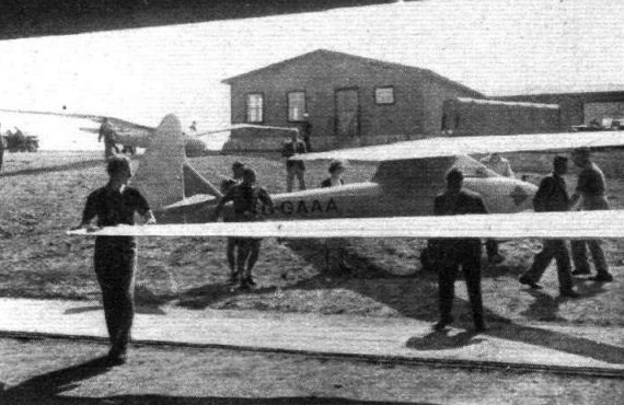
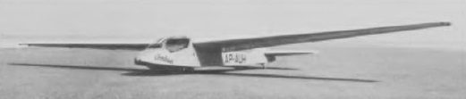
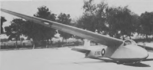
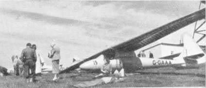
It was bought eventually by Messrs Brink & Horrell in Johannesburg. Very little was heard about its exploits after it left Britain, but it was flown in South Africa for some years. A rare photograph shows that, to begin with at least, it retained its British civil registration letters, G-GAAA, and the 1937 Wasserkuppe competition number 15 remained on the nose. Officially it was registered as ZS-23. It was used late in 1939 by E. Dommisse for a record height climb to 3,600m (12,000ft) above ground, which, since the take-off was from Quaggaport 1,740m (5,800ft) above sea level, represented an altitude of 5,340m (17,800ft) without oxygen breathing apparatus. The last 1,200m (4,000ft) of the ascent were in cloud without blind flying instruments, Dommisse relying on his airspeed indicator and a simple cross-level bubble.

What finally became of Hjordis is not known.

Slingsby Hjordis
Wingspan: 15.54 m (51 ft 0 in)
Wing area: 11.52 m2 (124.0 sq ft)
Aspect ratio: 21
Airfoil: Göttingen 652 at root, RAF 32 at tip
Length: 6.58 m (21 ft 7 in)
Empty weight: 144 kg (317 lb)
Gross weight: 218 kg (481 lb)
Rate of sink: 0.61 m/s (120 ft/min) minimum
Lift-to-drag: 24
Wing loading: 18.9 kg/m2 (3.9 lb/sq ft)
Crew: 1

Slingsby T-67 Firefly

T-67B

The Fournier company in France, manufacturer of a range of sporting aircraft, was in receivership and its RF6B, an aerobatic two-seat club trainer with fabric covered steel-tube fuselage and wood-and fabric wing designed in the early 1970s, looked promising. Slingsby bought the last of the RF6B line, numbering 10 or so aircraft in various stages of completion, along with all manufacturing rights, and called it the T67A.

Those aircraft were leased out to various aero clubs in the United Kingdom and the clubs were asked for their full and frank comments. At the same time, the T67A was being re-engineered for production in fibreglass at Kirbymoorside, Yorkshire, but retaining the shape and all the RF6B’s good points, and incorporating suggestions filtering back from the aero clubs. The end result was the Slingsby Firefly, a range of aerobatic trainers of differing engine power in the one airframe.

The Slingsby T67 Firefly was the world’s first aerobatic GRP aircraft to receive full public transport certification, meeting both the British BCAR and American Aviation Administration FAR part 23 requirements.

First flown in May 1981, the base model is the T67B, with the 116 hp Lycoming engine. The T67C has the 160 hp Lycoming carburettor engine, still with fixed-pitch propeller, while the T67D is fuel-injected, 160 hp, and with constant-speed propeller, as well as having wing mounted 159 litre fuel tanks in place of the fuselage mounted 113 litre tank found in the B and C models. Next is the T67M (for military), still with the same engine as the D but with a few extra items of equipment that air forces can’t do without, and top of the line is the T67M200, with 200 hp fuel-injected Lycoming because the military doesn’t think of any aircraft in terms of less than 200 hp.

The most potent and best-balanced of them all is generally reckoned to be the 160 hp fuel-injected version, with full inverted everything, which will exceed all military specifications except horsepower. The M models come with inverted fuel and oil systems as standard equipment, while the lesser versions are all equipped with sump trays that retain a semblance of oil presssure under negative G, but of course run out of power upside down.
First flight of the T67M200 was made on 16 May 1985 and production examples are powered by a 200 hp (149 kW) Textron Lycoming AEIO-360-A1E engine. Customers for this version to 1990 include the Turkish Aviation Institute, King Air in Holland and the Royal Hong Kong Auxiliary Air Force. Production of the earlier T67B, C and D exceeded 90 aircraft.

From 1992 one-hundred and thirteen T-67 Firefly were operated in USAF service as T-3A Firefly (92-0625 to 0662, 93-0555 to 0596, and 94-0001 to 0033), wearing civil registrations, at Randolph Field TX.

Slingsby T-3A N31575

T67B
Engine: Lycoming O-235, 116 hp
Prop: fixed-pitch
Fuel cap: fuselage mounted 113 lt

T67C
Engine: Lycoming O-320, 160 hp
Prop: fixed-pitch
Fuel cap: fuselage mounted 113 lt

T67D – Engine: Lycoming IO-320, 160 hp
Prop: constant-speed
Fuel cap: wing mounted 159 lt

T67M Firefly
Engine: 1 x Lycoming AEIO-320, 119 kW
Span: 10.6 m
Length: 7.3 m
Wing area: 12.6 sq.m
Empty wt: 650 kg
MTOW: 907 kg
Max speed: 256 kph
Initial ROC: 360 m / min
Ceiling: 4570 m
T/O run: 190 m
Ldg run: 230 m
Fuel internal: 160 lt
Range: 980 km

T67M-200
Lycoming IO-360-A1E, 200 hp

Slingsby T-65 Vega / Vickers-Slingsby T-65 Vega

Designed by R. Sanders, the T-65 15m Contest Class single-seater is the first sailplane of entirely Slingsby design to appear since the liquidation of the former Slingsby Aircraft Co in July 1969 and its reorganisation as part of the Vickers group; it was later known as Slingsby Engineering Ltd (Aircraft Division). The Vega was designed to take advantage of the change in Standard Class rules permitting camber-changing flaps to be installed in this class after 1976. The all composite T. 65 was the first sailplane designed from the outset with a carbon fibre mainspar. The wings are of foam plastics sandwich construction with a single carbon-fibre main spar, which keeps the weight of each wing down to only about 130lb; the Wortmann wing section and carbon-fibre spar allow a constant 15% thickness/chord ratio from root to tip, giving performance benefits at the higher speeds. The wing tips are turned downwards to reduce tip stalling and are protected by inset metal rubbing strakes, and a convenient feature is that all controls are automatically coupled on rigging, leaving only the centre pin to be inserted. The wings also hold up to 195lb of water ballast in shaped plastic bags, thus avoiding any leakage which may occur when the wing itself is used as a tank. The cantilever mid-set wings are designed for optimum performance and have combined flaps/air brakes inboard and the ailerons outboard; the latter can be operated independently or in conjunction with the flaps. The wings have a unique single-lever operation for the flap and air brake system instead of using two separate levers as in other types; in the Vega the lever moves fore and aft in the usual way for air brake movement but is rotated by wrist action to select the flap positions which range from -12° to + 12°. The air brakes are hinged to the flaps with continuous flexible straps. Trim setting is adjustable by flap setting for hands-off flight at most operating speeds. Also automatic are the coupling of control and ballast-dumb plumbing on rigging.

The Vega prototype first flew on 3 June 1977 and, after some initial problems resulting from stiffness of the single-lever flap/air brake control, resumed test flights in November that year; the first production delivery was in April 1978, by which time 48 had already been ordered.

The fuselage is a conventional semi-monocoque plastics structure, and is gently ‘waisted’ to reduce the possibility of airflow separation over the wing/fuselage junction; the tow hook is carried on the frame that carries the monowheel, and retracts with it. The latter has a brake, and an unusual feature for a sailplane is that the Vega’s tailwheel retracts as well. The pilot sits upright under a long one-piece canopy which opens forwards and upwards, and is jettisonable. The cantilever T-tail has a tailplane of symmetrical Wortmann section with a carbon-fibre spar and a separate elevator with a spring trimmer.

The A model has glass wing skins and 100 kg/ 220 lb of water ballast, while the D model has Kevlar skins for added strength and 160 kg./ 352 lb of ballast. The T. 65C model is a Sports Class variant. The T65C Sport Vega first flew on 18 December 1979, and this version differs from the Vega in having a glassfibre main spar, rotating trailing edge air brakes instead of flaps, and a fixed monowheel and tailwheel. There is no provision for water ballast. The T.65D was first built in 1979 with a standard price at the time of US$17,900. At the time it was produced, the Slingsby company operated under the name Vickers-Slingsby, but the Vickers part was subsequently dropped.

By the beginning of 1980 34 Vegas had been delivered.

Span: 49 ft 2.5 in
Length: 22 ft 0.5 in
Height: 4 ft 11 in
Wing area: 108.2 sqft
Aspect ratio: 22.4
Empty weight: 515 lb
Max weight: 970 lb
Max speed: 155 mph (in smooth air)
Max aero-tow speed: 92 mph
Min sinking speed: 2.21 ft/sec at 51 mph
Best glide ratio: 42:1 at 69 mph

T.65D
Wing span: 15m / 49.2ft
Wing area: 10.05sq.m / 108.2sq.ft
Length: 22 ft
Height: 4.75 ft
Empty Weight: 236kg / 520lb
Payload: 600lb / 272kg
Gross Weight: 1120lb /508kg
Wing Load: 10.35lb/sq.ft / 50.5kg/sq.m
Water Ballast: 352lb /160kg
Airfoil: Wortmann FX 67-K-150
Aspect ratio: 22
MinSink: 0.56 m/s / 1.85 fps / 1.10 kt
No. of Seats: 1
L/DMax: 42.1 @ 111 kph / 60 kt / 69 mph
Max speed: 135 kt
Stall speed: 34 kts
Rough air airspeed: 135 kts
No. Built: 80
Structure: carbon fibre main spar, Kevlar wing skin, fibreglass fuselage and tail

Vega
Wing span: 15.0 m / 49 ft 2 in
Length: 6.72 m / 22 ft 0.5 in
Wing area: 10.05 sq.m / 108.2 sq ft
Wing section: Wortmann FX-67-K-150/FX-71-L-150
Aspect ratio: 22.4
Empty weight: 234 kg / 516 lb
Max weight: 440 kg / 970 lb
Water ballast: 88 kg / 195 lb
Max wing loading: 43.8 kg/sq.m / 8.97 lb/sq ft
Max speed: 135 kt / 250 km/h
Stalling speed: 36 kt / 67 km/h
Min sinking speed: 0.67m/sec / 2.21 ft/sec at 44 kt / 82 km/h
Best glide ratio: 42 at 60 kt / 111 km/h

Slingsby T-53

Made distinctive by its swept forward wing and the extensive area of its transparent canopy glazing, which extends back to the wing trailing edge, the T53 tandem two-seater trainer was designed by J. L.Sellars and was Slingsby’s first all-metal type. The type is intended for initial or advanced training and the prototype, the T53A, made its first flight at Wombleton, Yorkshire, on 9 March 1967. It had tapered wings with camber-changing flaps with a range of 5° up to 15° down, ailerons of large chord and an all-moving tailplane.

T.53B

The first production version, the T53B, made its first flight on 28 March 1968, and had the cockpit moved forward, the structure redesigned and simplified, the flaps deleted and the all-moving tailplane replaced by a conventional tailplane and elevators; the aileron chord was also reduced and these changes resulted in lighter stick forces and a considerable saving in weight. The T.53B features two fixed tandem wheels and a swept- forward flapless wing of constant chord (the prototype T.53A had flaps).

Slingsby T.53B

Of light alloy stressed skin construction throughout, the T53C has two-spar cantilever shoulder wings with 3° forward sweep at the quarter-chord line as compared to the 5° 15′ forward sweep of the T53B; the ailerons are mass-balanced and there are Schempp-Hirth air brakes in the upper and lower surfaces. The fuselage is a semi-monocoque and the cantilever tail unit has an internal spring-loaded trimmer. Landing gear consists of a non-retractable main wheel and nose wheel (or skid on the ATC variant), plus a tailskid; main wheel shock absorption on the T53C is by Armstrong damper units and there is an expanding caliper brake. The pilots sit under a sideways-hinging moulded flush Perspex canopy, and radio and an oxygen system can be fitted if desired.

The first T53B, XV951, was in RAF markings for air cadet training, and there were a number of modifications made to meet ATC requirements. These included fitting a nose skid in place of the standard nose wheel, to shorten the landing run; fitting a ground rapid-retrieve facility to improve utilisation in circuit training; fitting a performance retarding device for basic pilot training and making the main wheel spring-loaded. It was also envisaged that the ATC variant could be operated with open cockpits if the crew’s comfort demanded.

T.53B

But in the end it was the T53C that was built in small numbers for the ATC, the variant incorporating the special ATC modifications being known as the T53C(M).

The C, which first flew in May 1970, had a revised and extended fin and rudder with extra area above the tailplane, no dorsal fin, a structurally redesigned wing, reduced aileron control loads resulting from the use of aileron servo tabs, a revised spring trim system and improvements in the cockpit layout, seating, ventilation and canopies; some extra equipment was carried and the all-up weight was increased.

The T53D project of October 1968 was a semi-aerobatic powered trainer version with a pusher engine installed on the port wing only, and a fuel tank in the wing leading edge, and the T53E was another project for a powered trainer version of the T53C.

Only 16 T53Bs and one more T53C (actually the last T53 converted) were built before the November 1968 fire at Slingsby’s works put a stop to production, but the design was later acquired by Yorkshire Sailplanes, who had built three more as the YS.53 Sovereign by 1974. This differed from the T53B chiefly in having longer tail surfaces and a
nosewheel instead of nose skid.

Variation:
Yorkshire Sailplanes YS.53 Sovereign

T53C
Wing span: 17m / 55.5 ft 6 in
Wing area: 18.02 sq.m / 194 sq.ft
Aspect ratio: 15.9
Airfoil: Wortmann FX 61-184
Length: 7.7 m / 25 ft 3.25 in
Height: 1.83 m / 4 ft 7.25 in
Empty Weight: 354 kg / 780 lb
Payload: 226 kg / 499 lb
Gross Weight: 1279 lb / 580 kg
Wing Load: 6.59 lb/sq.ft / 32.19 kg/sq.m
Water ballast: None
Max speed: 135 mph / 117 kt / 217 km/h
Max rough air speed: 80 kt / 148 km/h
Stalling speed: 40.5 kt / 75 km/h
L/DMax: 29 @ 89 kph / 48 kt / 55 mph
MinSink: 0.76 m/s / 2.5 fps / 1.48 kt at 50 mph / 43 kt / 80 km/h
No. of Seats: 2
No. Built: 21
Structure: metal

Slingsby T-51 Dart

Dart 17

This high performance Standard Class single-seater was the last Slingsby type of conventional all-wood construction and the last to be designed under Mr F.N. Slingsby’s direction.

The T.51 Dart 15 rear fuselage is long and slim with a small fin and tailplane. The overall length of the fuselage is the same as the length of one wing. The general arrangement and size of the cockpit is the same as that of the Skylark 4, although the fuselage depth is reduced by 10 cm (4 in). This is achieved by running the flying controls along the side of the cockpit instead of under the pilot’s seat. The tailplane is of the all-moving type with anti-balance tabs.

The Dart was originally designed to Standard Class rules and the prototype Dart 15 first flew on 26 November 1963 and the Dart 15 – known as the 15R when fitted with a retractable monowheel – was the initial Standard Class version with 15m span shoulder wings, which were cantilever single spar spruce structures with a birch plywood leading edge torsion box and a fabric-covered rear portion; there were air brakes at the 50% chord line and the plain ailerons were plywood-covered. The wing spars were initially entirely of wood, but were later changed to box spars of mixed wood and light alloy construction with Redux bonding when this type of spar was introduced into the Dart 17 in 1965. Wing root fillets like those on the Dart 17 were also fitted at this time and later production Dart 15s had an all metal tailplane.

Slingsby T-51 Dart Air Test

Altogether 50 Dart 15s were built, plus five more constructed from kits supplied by Slingsby, four of these being built by Mr Fred Dunn in New Zealand; the price of a Dart 15 in July 1964 was £1,425.

This verison scored a number of competition successes: one flown by G. Burton gained 5th place in the Open Class at the 1965 World Championships at South Cerney, Gloucestershire, and the Dart 17 prototype, flown by H. C. N. Goodhart, took 7th place in this event. The Dart 15 was awarded the OSTIV Design Prize at these 1965 Championships. In League One of the 1967 British Championships, Darts came 1st and 2nd and took eight more of the first 20 places. In 1965 Dick Georgeson of New Zealand set a world Out & Return record of 730.6 km./ 453.98 miles in a Dart 15.

Dart 15 W

But the Dart 15 in its wooden-sparred form was really too heavy and did not really have the performance for soaring in average British conditions, and this led to the Dart 17 – or 17R with retractable monowheel – with the span increased to 17m, this now being the Open Class version; the prototype 17 first flew in November 1964 and the price of a 17R was £1,950 in August 1966. Altogether 44 Dart 17s and 17Rs were built, plus four more built from kits in New Zealand by Fred Dunn. There was also one Dart 15/17, G-ATOE, which had detachable wing tips for changing the span from 15 to 17m, and two examples of the Dart 15W were built, this being a special version for the British team in the 1968 World Championships in Poland. The 15W had a new Wortmann wing section instead of the previous NACA 64-series aerofoils, a revised canopy shape and cockpit interior; the 15W first flew at Lasham on 29 March 1968 and after the Championships both 15Ws were convertred to Dart 17Ws with the 17m span wing, first flying in this form on 3 May 1969, and both were later fitted with retractable monowheels, in which form they were designated Dart17WR.

T.51 Dart 17

Most Dart 15s and 17s had the retractable wheel, which became available as an optional fitting at the end of 1965, and this allowed a change of wing incidence, thus avoiding the Dart’s tail-high attitude when flying at high speeds. All-metal tailplanes were also fitted to the later production Dart 17s. With the original wooden spar wing, flexure was caused when the Dart 17’s air brakes were extended, and so to reduce this a new box spar with light alloy booms Redux-bonded to wooden webs was introduced, the first Dart 17 with this spar being rolled out in April 1965. At the same time the aileron span was increased by 11.75in, and new wing root trailing edge fillets were added to reduce drag. On the Dart 15 the new spar resulted in a saving of 45lb in tare weight over the wooden-sparred version. The Dart’s fuselage is a semi-monocoque spruce structure of elliptical cross section, the cockpit section being covered with glassfibre and the remainder with birch plywood. The pilot sits in a semi-reclining seat under a sideways hinging moulded Perspex canopy with clear vision panels, and the cockpit is very similar in size and general arrangement to the Skylark 4’s. The fuselage is shallower than the letter’s because the flying controls run along the sides of the cockpit instead of under the pilot’s seat. The fin and rudder are of spruce with glassfibre leading edges, the rudder being fabric-covered, and the light alloy stressed skin tailplane, previously wooden, is an all-moving surface with anti-balance tabs. As well as the monowheel, which has an expanding brake, there is a short forward skid under the nose and a tail bumper fairing.

Slingsby T51 Dart 17

A total of 81 Darts were built.

T.51 Dart 15
Wing span: 15m / 49.2ft
Wing area: 12.5sq.m / 136sq.ft
Wing section: NACA 64s618/615
Aspect ratio: 18
Length: 7.47 m / 24 ft 6 in
Empty Weight: 218kg / 480lb
Water ballast: None
Payload: 122kg / 270lb
Gross Weight: 750lb / 340kg
Max speed: 116 kt / 215 km/h
Stalling speed: 35 kt / 65 km/h
Max rough air speed: 80 kt / 148 km/h
Wing Load: 5.51lb/sq.ft / 27.21kg/sq.m
L/DMax: 31 @ 87 kph / 47 kt / 54mph
No. of Seats: 1
MinSink: 0.76 m/s / 2.5 fps / 1.48 kt at 41.5 kt / 77 km/h
Structure: wood/ metal bonded spar, metal tailplane

T51 Dart 17 R
Wing span: 17 m / 55ft 9.25 in
Wing area: 13.87 sq.m / 149.3 sq.ft
Aspect ratio: 20.4
Wing section: NACA 6433618/615
Length: 7.54 m / 25 ft 5 in
Empty Weight: 243 kg / 535 lb
Payload: 88kg / 195lb
Water ballast: None
Gross Weight: 331kg / 730lb
Wing Load: 4.89 lb/sq.ft / 23.86 kg/sq.m
Max speed: 136 mph / 119 kt / 220 km/h (in smooth air)
Max rough air speed: 117 kt / 216 km/h
Stalling speed: 35 kt / 65 km/h
L/DMax: 37 at 87 kph / 47 kt / 54 mph
MinSink: 0.58 m/s / 1.97 fps/ 1.13kt at 46 mph / 40 kt / 74 km/h
No. of Seats: 1

T.51 Dart 15
T.51 Dart 17R

Slingsby T-50 Skylark 4

Although developed from the later versions of the Skylark 3, the Skylark 4, with its new and shallower fuselage with the pilot sitting in a semi-reclining position, and its new outer wings and ailerons giving a wing span of exactly 18m (59ft 0.5in), was almost a new design. It was developed through the Slingsby T47, a verison of the Skylark 3 projected in December 1958 with a span of 20m (65ft 7in) created by increasing the span of the constant chord centre section; the wing area was now 193.45sq ft and the aspect ratio 22.2. The Skylark 4 has the wings faired directly into the top of the fuselage without the built up pylon-type structure behind the cockpit of the Mks 3 and 2, the height of the wing being 9in lower than the Mk3’s. The wing is very similar to that of the 3G but has modified wing roots, and the main spar has been strengthened to avoid the Mk 3’s tendency for the wing tips to be deflected downwards at high speed.

The prototype Skylark 4 first flew in February 1961 and altogether 63 Mk 4s were built, plus three more constructed in New Zealand by Mr Fred Dunn from kits supplied by Slingsby. The Mk 4 was successful in competitions, and scored two notable successes in 1963 when examples of this version won both the US and Canadian National Championships.

Structurally the Mk 4 was very similar to the Mk 3, with a light rear spar carrying the ply-covered ailerons, the wing being plywood-covered to the rear spar and with a fabric-covered trailing edge; the air brakes in both upper and lower surfaces are on the 50% chord line. The wooden fuselage is a semi-monocoque of elliptical cross section with a glassfibre-covered nose and plywood covering for the remainder. The pilot sits under a moulded Perspex canopy that is larger than the Mk 3’s, and likewise hinges sideways to open. Landing gear consists of a non-retractable Dunlop monowheel with rim brake, a rubber-sprung nose skid and a tail bumper. The fin and tailplane are plywood-covered and the rudder and elevators fabric-covered, with a trim tab in the starboard elevator.

The Royal Air Force operated 4 (known as the Swallow T. Mk. 1) in its air cadet training program. Altogether 192 Skylark Mks 1-4 were built.

Skylark 4
Span: 59 ft 0.5 in / 18 m
Length: 25ft 1 in
Height: 5ft 3in
Wing area: 173 sqft
Aspect ratio: 20.5
Empty weight: 570 lb
Max weight: 830 lb
Mex speed: 135 mph
Max aero-tow speed: 80 mph
Min sinking speed: 1.74 ft/sec at 43mph
Best glide ratio: 36:1 at 47 mph
No. of Seats: 1

T.50 Skylark 4
Wing span: 18.16 m (59 ft 7 in)
Length: 7.64 m (25 ft 1 in)
Wing area: 16.07 sq.m (173 sq.ft)
Wing section: NACA 633620/6415
Aspect ratio: 20.5
Empty weight: 253 kg (558 lb)
Max weight: 376 kg (829 lb)
Water ballast: None
Max wing loading: 23.4 kg/sq.m (4.79 lb/sq ft)
Max speed: 118 kt (219 km/h)
Stalling speed: 32 kt (60 km/h)
Min sinking speed: 0.53 m/sec (1.74ft/sec) at 37 kt (69 km/h)
Max rough air speed: 71 kt (132 km/h)
Best glide ratio: 36 at 41 kt (76 km/h)

Slingsby T.49 Capstan

Slingsby T49B Capstan

Intended as a successor to the T42 Eagle the Capstan side-by-side two-seater is designed to be suitable for all stages of dual instruction, and also for club or private owner use; a wide cg range enables it to be flown solo when required.

Design work began in 1960 and the prototype, the T49A first flew on 4 November 1961; this differed slightly from the T49B production version, having a smaller fin and rudder.

Of conventional wooden construction, the Capstan has glassfibre covering for the nose section and other double curvature panels and fairings, with ply and fabric covering elsewhere. The cantilever high-set single-spar wings have a plywood leading edge torsion box and fabric coveirng aft of the spar; there are dive brakes in the upper and lower wing surfaces and the ailerons are plywood-covered. The wings are attached to each side of the fuselage with three pins, making for ease of rigging. The forward fuselage is made up of spruce frames attached to a central keel box and is covered in glassfibre, while the rear fuselage is a braced wooden girder structure, with a bottom skin of plywood and the top and sides fabric-covered. The fixed surfaces of the cantilever tail unit are plycovered and the control surfaces fabric-covered; there is a trim tab in the starboard elevator. There is a nose skid under the forward fuselage mounted on a full-length rubber shock absorber, and a fixed Dunlop monowheel with a band brake, plus a leafspring tailskid. The two pilots sit under a rearward hinged one-piece Perspex canopy, and all controls are duplicated except for the tow release and elevator trimmer.

Production started in the spring of 1963, and altogether 31 T49B Capstans were built, plus two more constructed in New Zealand by Mr Fred Dunn from kits supplied by Slingsby; price of the T49B was £1,750 in October 1963.

The T49C Powered Capstan was a standard Capstan fitted with a 45hp Nelson H-63CP four cylinder two-stroke engine mounted on a pylon behind the cockpit and driving a pusher propeller. Small wing tip wheels and a tail wheel instead of a skid were fitted. The prototype, G-AWDV, first flew on 15 February 1968 at Wombleton, Yorkshire, but was burnt out in the fire that destroyed Slingsby’s factory in November that year. It had been intended to make complete ‘power eggs’ available to convert existing Capstans but this idea was not proceeded with. The T49C had a maximum level speed of 85mph, a sea level rate of climb, when flown solo, of 510ft/min, and a take-off run of 420ft with two pilots.

The Capstan was Slingsby’s last wood two-place design.

T.49 Capstan
Wing span: 16.76 m (55 ft 0 in)
Length: 8.07 m (26 ft 6 in)
Height: 1.58 m (5 ft 2.5 in)
Wing area: 20.43 sq.m (220 sq.ft)
Wing section: NACA 63-620/6412
Aspect ratio: 13.75
Empty weight: 345 kg (761 lb)
Max weight: 567 kg (1,250 lb)
Water ballast: None
Max wing loading: 27.75 kg/sq.m (5.68 lb/sq.ft)
Max speed: 117 kt (217 km/h)
Stalling speed: 32.5 kt (60 km/h)
Min sinking speed: 0.66 m/sec (2.17 ft/sec) at 37.5 kt (70 km/h)
Max rough air speed: 80 kt (148 km/h)
Best glide ratio: 30 at 41 kt (76 km/h)

T.49B Capstan
Wing span: 16.78 m / 55 ft 0 in
Wing area: 20.43 sq.m / 219.9 sq.ft
Length: 26 ft 6 in
Height: 5 ft 2.5 in
Empty Weight: 345 kg / 761 lb
Payload: 222 kg / 489 lb
Gross Weight: 1250 lb /567 kg
Wing Load: 5.68 lb/sq.ft / 27.7 kg/sq.m
Aspect ratio: 13.75
L/DMax: 30 @ 84 kph / 45 kt / 52 mph
No. of Seats: 2
MinSink: 0.79 m/s / 2.17 fps / 1.54 kt at 43.5 mph
Max speed: 135 mph
No. Built: 34
Airfoil: NACA 63-3-620
Structure: all wood, fiberglass nose and fairings

T.49B Capstan
Engine: Nelson, 45 hp / 34 kW
Wing span: 16.78m / 55ft
Wing area: 20.43sq.m / 219.9sq.ft
Aspect ratio: 13.78
No. of Seats: 2
Airfoil: NACA 63-3-620
Structure: all wood, fiberglass nose and fairings

Slingsby T-46

A two seat, side by side glider, a developed version of the Type 21B with larger wing span, enclosed cockpit, and revised tail unit. Braced wing, with airbrakes, no flaps.

Wing span: 17.22m / 56ft 6in.
Length: 8.15m / 26ft 9in
Wing span: 25.36m / 273.75 sq. ft
Aspect ratio: 11.7
Wing sections: Gottingen 535 at root, Sym. at tip

Slingsby T-45 Swallow / Reussner Swift

Described as ‘a poor man’s Skylark’, the Swallow single-seater was intended to meet the need for a small moderately-priced high performance sailplane for clubs and the private owner.

Slingsby T.45 Swallow Article

Of conventional wooden construction, the Swallow has cantilver high-set wings of spruce and plywood, with single spars, plywood covering and a leading edge torsion box; the wooden fabric covered ailerons are unbalanced and there are dive brakes in the wing upper and lower surfaces. The forward fuselage is a plywood semi-monocoque while the rear portion is a braced structure of spruce and plywood with fabric-covered sides. The wooden tail unit has ply covering for the fin and tailplane and fabric covering for the rudder and elevators. Landing gear consists of a rubber-sprung skid under the nose, a fixed unsprung monowheel and a tailskid.

The prototype first flew on 11 October 1957 with a span of 39ft 4in (12m) but this was increased to 42ft 9.25in to improve performance. The type, then unnamed, got its name when the prototype, flown by John Reussner, crashed and ended up hanging from some telephone wires – ‘just like all the other swallows’, said Mr F. N. Slingsby, who witnessed the accident and promptly dubbed the type Swallow. Reussner later acquired the prototype and rebuilt it as a standard Swallow; it became BGA 865 in October 1958. It was later modified to his own ideas as the Reussner Swift, with the span increased to 15m (49ft 2.5in) by extending the wing roots, lengthening it by a 1ft insert in the rear fuselage, and fitting a revised canopy similar to that of the Swallow 2. As the Swift it became BGA 966 and crashed on 24 November 1963 at Netheravon, Wiltshire.

The Swallow 1 prototype was followed by the Swallow 2 production version which differed in having a revised canopy of slightly different shape; the type was sold to nine different countries and a total of 106 were built up to 1968 before production was terminated by the fire at Slingsby’s Kirbymoorside factory, plus 10 more constructed from kits supplied by Slingsby for amateur constructors.

The Royal Air Force operated 4 (known as the Swallow T. Mk. 1) in its air cadet training program.

The Swallow 3 project of January 1968 was a variant designed for that year’s Swallow Competition organised by the cigarette firm of W. D.& H. O. Wills, with which British sailplane pilot Philip Wills was associated; the Mk 3, which was not built, had a revised nose shape incorporating a flush-fitting one-piece canopy with no step, and the wing span was increased to 24ft and the area to180sqft.

While Fred Slingsby was taking photgraphs of the prototype T.45 at Sutton Bank, John Reussner crashed and ended up with the glider hanging up in telephone wires, ‘just like all the other Swaallows’ commented Fred. ‘Just for that we’ll call it The Swallow’.

John Reussner rebuilt the prototype as a standard Swallow, with a c/no of JCR.1, and it received a BGE C of A in October 1958, BGA 865. It was later modified and final appeared as the Swift.

The modifications included extending the wingspan to 15m by adding a parallel chord section to each wing root, lengthening the fuselage by 1 foot, this added to the rear fuselage between the trailing edge of the wing and the tailplane. A revised canopy was also fitted.

The Reussner Swift was allocated c/n JCR.2and received a C of A BGA.966 in August 1960.

It crashed at Netheravon, Wiltshie, on 24 November 1963 and was written off. The pilot was killed, but it was later established he had suffered a heart attack while in the air.

T.45 Swallow
Span: 13.2m / 42 ft 9.25 in
Length: 7.04 m / 23 ft 2 in
Height: 1.58 m / 5 ft 2.5 in
Wing area: 13.55 sq.m / 145.9 sq.ft
Aspect ratio: 12.6
Wing section: NACA 63-618/4412
Empty Weight: 195 kg / 431 lb
Payload: 122 kg / 469 lb
Gross Weight: 317 kg / 700 lb
Wing Load: 4.8 lb/sq.ft /23.4 kg/sq.m
Water ballast: None
Max speed: 141 mph / 122.5 kt / 227 km/h
Stalling speed: 33.5 kt / 62 km/h
Max rough air speed: 75 kt / 139 km/h
MinSink: 0.76 m/s / 2.5 fps / 1.48 kt at 36 kt / 67 km/h
L/DMax: 26 @77 kph / 42 kt / 48 mph
No. of Seats: 1
No. Built: 116
Structure: wood and fabric

Reussner Swift
Wingspan: 15.0 m / 49 ft 2 in
Length: 7.37 m / 24 ft 2 in