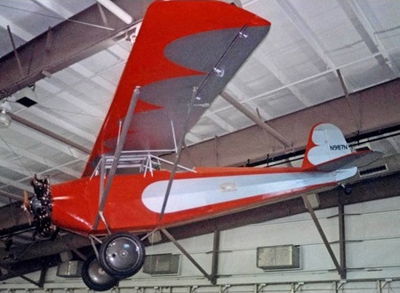
Temple Sportsman N987N on display at the Frontiers of Flight Museum at Dallas, Texas
Designed by George W Williams and George Carroll, the Sportsman was a parasol winged monoplane, equipped with two seats arranged in tandem. The cockpit had an open layout. A fixed tail-wheel undercarriage was fitted. The tailplane was set low on the fin. A 100 h.p. Cirrus III was initially fitted.
Three examples of the Sportsman were completed: NC480 manufacturers number 1; NC852H and N987N manufacturers number 107. There was no N987N registered in FAA records at the time, so it is likely to be from a later registration. There was an NC987H, but that was the registration for a different make of aircraft, a Smith S-1 with a Velie engine. The Sportsman was suitable for operation by individual sporting pilots. Williams was killed during 1930 in the crash while flying with a trainee pilot. The company folded after the accident.
One Texas-Temple Sportsman still exists. It had been found in bits by an airplane restorer, Jerry D Ferrell, who reconstructed it. The plane undertook its airworthiness test on July 26, 1990. Ferrel donated the plane for display at the Frontiers of Flight Museum, Love Field, Dallas, Texas. The plane is fitted with a Clyde Cessna modified engine, the Anzani.
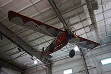
The Texas-Temple Sportsman on display at the Frontiers of Flight Museum
The one-off Texas Parasol Ontario Modifications, C-IVME, was built to fit Canadian Ultralight regulations. Texas Parasol uses a VW engine, plus small “Ontario” modifications, and the approximate cost to build was less than $5000.
The Texas Aircraft Factory Me 262 has its origins as an original 262 found in a dilapidated state at Willow Grove Naval Air Station, Pennsylvania. The aircraft, one of 11 examples taken to the United States in 1945 and, while none flew again, they did assist America with its jet aircraft development programme. There were no blueprints for the sheet metal and wood 262 and the aircraft was gradually disassembled and all parts duplicated with enough to make five new aircraft. Its original Junkers engines were unreliable and needed overhauling every ten hours, and accordingly the new jet has two General Electric J 85 engines, giving twice the power and half the weight of the originals.
The Me 262 was a stunning design triumph, and the influence of the plane can still be seen in contemporary combat aircraft. Swept wings, automatic slats, modular construction … all were leading advances for the time. More than any other aircraft of its day, the 262 was a fighter of absolutely unrivalled potential.
Still, despite this fortuitous blend of brilliance and chance, the Me 262 suffered from some well-known, and potentially catastrophic, weaknesses. The engines, landing gear and brakes were all decidedly failure-prone, and these systems often caused the losses that the Allies could not.
One of the most overlooked aspects of the Me 262 Project lies in the extraordinary engineering and design work that has gone into integrating authenticity with safety. In our desire to create a worthy duplication of the original aircraft, we have developed a number of ultra-low profile improvements which will greatly enhance operator and flight safety. In the case of the J-85 replacing the Jumo 004, this is a rather overt matter; however, several other critical improvements have been quietly incorporated into the design to insure that these jets do not suffer the same fates as so many of their predecessors.
The precision engine castings were first proposed, then designed, by the late Steve Snyder. As an aeronautical engineer, Snyder recognized that simply hanging a pair of J-85s on the Me 262 within oversized cowlings would create as many problems as it solved. Differences in wing root forces, weight distribution, and the Center of Gravity would have completely altered the characteristics of the original Me 262. His solution may have been borne of necessity, but it has emerged as one of the most innovative engineering feats in the entire effort.
Detailed castings have been made from an original Jumo engine, and all related accessory drive components, gearboxes and pressure lines will be precisely duplicated for surface-mounting. When the access panels are opened, bystanders will see a historically accurate duplicate of a Jumo 004B engine. Concealed deep within the casting, the modern powerplant will go all but completely unnoticed.
Perhaps most significantly, the entire assembly (when mated with the J-85) will closely duplicate the nacelle weight of the original Jumo 004. In this respect, the original performance characteristics of the aircraft will be faithfully preserved.
As the landing gear was known to be another weak area on the original Me 262, a detailed analysis of landing gear stresses was directed. This process revealed that a shock loading was generated by the spin-up forces of the large, heavy main wheels, which had to be reacted into by the wing landing gear attachment structure. This placed a severe demand upon wing spar area and the airframe simply had to absorb these forces. Over time, this would have had a devastating effect upon the aircraft.
In part, this problem can be traced to the history of the aircraft. As originally designed, the Me 262 was equipped with a standard tail wheel (in lieu of the nose wheel).
In the tail-dragger configuration, the main gear was bolted directly onto the wing spar; however, the tricycle modification resulted in the creation of a separate wing torque box to be used as a mounting point. This torque box was susceptible to damage, and very difficult to repair.
On the new Me 262s, this area has been reinforced with additional structural features, and the project is considering additional design changes that may further enhance the safety and longevity of the landing gear. In addition to the wing box reinforcement, the nose gear mounting point and strut assemblies have been greatly improved. In short, the entire system has been strengthened by a significant margin above what it was originally.
The braking systems of wartime German aircraft usually left something to be desired, and the Me 262 was no exception. Brake fading and/or complete system failures were a common complaint.
The notoriously ineffective nose wheel brake has been eliminated altogether, although the original brake lines will be duplicated for appearance. Meanwhile, the marginally performing drum brakes on the main gear have been replaced by a cleverly-integrated disc brake system. The improved disc brakes have been mounted within the wheel hub assembly itself, and have the capacity to stop an aircraft more than twice the weight of the Me 262.
Despite the fact that the nacelle weight will be roughly equal to that of the original Me 262, the power available to the pilot has still been significantly improved. Since the characteristics of the airplane were well known at the 1,800 pound thrust level, every effort has been made to duplicate this performance envelope, and not create some “Super Me 262” class airplane. Still, the fact remains that the increase in thrust is significant enough to consider some entirely new engineering aspects.
While a positive development in most respects, the added power can present new problems of its own. For example, an engine failure during a full power takeoff could quickly result in an uncontrollable asymmetric thrust component. The project engineers understood this problem, and developed a simple method to control the situation. To address these issues and provide the pilot an accurate indication of actual power settings, the project has carefully modified the throttle assembly to be fitted with a throttle pressure spring which provides a positive force indication of engine RPM at 1,800 lbs. thrust. In other words, the pilot will know when the maximum specification thrust levels of the Jumo 004 have been reached.
If the pilot desires additional power, he may push the throttles beyond the spring loaded position, holding them open against this spring pressure. The actual hard stop for the throttles will be set at the J-85’s maximum thrust setting, which is projected to be around 2,400 to 2,500 lbs., as mounted. The additional power is reserved for two operational regimes. On takeoff roll, prior to liftoff, and during climb. Takeoff roll is initiated with full power, but it is then reduced to the original Jumo takeoff thrust level (1,800 lbs.) just prior to liftoff. The excess power may be added once safe climb speeds of 260 Miles Per Hour are achieved.
The Junkers Jumo 004 is often remembered as a temperamental and failure-prone powerplant. Despite its advanced design, engine life was only between 10 and 25 hours, with the mean being at the lower end of this range. These failures were anticipated to some extent and the Me 262 was designed to permit extremely rapid engine changes. Contrary to popular belief, the 004A was a fairly sound performer when premium steels were used, and early versions were known to achieve a 200-250 hour service life. However, the diversion of critical materials into U-boat production and other projects late in the war forced Junkers to produce the 004B model with only 1/3 of the high grade steel that had been used in the 004A. It was to be a disastrous concession for the Me 262.
The introduction of inferior metals compounded an already problematic situation with the turbine blade design. These blades were rigidly mounted, contributing to severe root stress relief problems. The weaker metals simply could not withstand this kind of abuse and regular compressor failures were an inevitable consequence.
The General Electric J-85/CJ-610 series turbojet engine was originally designed in the 1960s for use in military applications. Shortly thereafter, civil certification and production followed under the CJ-610 designation. The CJ-610 was quickly selected to power the popular Gates Learjet; meanwhile, its military cousin was called into service with such noteworthy combat aircraft as the F-5 Freedom Fighter and A-37 Dragonfly. The resilience and forgiving qualities of the engine also made it a natural choice for training aircraft, and the J-85 was adopted for both the T-38 Talon and T-2J Buckeye.
The J-85/CJ-610 engine has a reputation for extreme reliability, allowing wide variations of inflow distortion. It also places a minimal maintenance burden upon ground crews. Proven in war and in peace over three decades, the engine is ideally suited to power this classic warbird well into the next century.
In aircraft applications, engine power is characteristically measured in terms of thrust versus weight. The Jumo 004 was typical of early jet engines in that it was rather heavy, and not especially efficient. Production model 004s produced 1,980 lbs. of thrust, and weighed in at about 1,800 lbs. Because of this, the engines were not extraordinarily effective at low airspeeds or altitudes or at reduced power settings. Long takeoff rolls (>3,000′) were evidence of this phenomenon and, once aloft, power management became critical. Abrupt throttle changes or rapid maneuvering often resulted in a flameout, or worse, a complete compressor failure. Each J-85 produces 2,850 lbs. of thrust, yet weighs only 395 lbs. In simpler terms, the new engines offer nearly twice the power for less a quarter of the Jumo’s weight penalty. The design dynamics of the Jumo engine castings are expected to reduce the thrust available by about 300 lbs. per engine. Engineering estimates call for an actual power output in the vicinity of 2400-2500 lbs. per engine. Integration of the J-85 will bring many noticeable improvements. Takeoff distances will be significantly shortened (<2,000′), and time-to-climb rates vastly improved. Also, the J-85 responds well to varying power demands (including low power settings) and is highly tolerant of the kind of airflow disruptions that gave the Jumo such difficulty.
The Jumo-powered Me 262 was capable of level flight speeds in excess of 540 miles per hour at altitude; a trait that made it all but invulnerable to Allied escort fighters. Higher airspeeds were recorded under certain circumstances but, in general, compressibility-related aerodynamic factors prevented the airframe from ever pushing into the high transonic range. Postwar tests in the West confirmed that at very high airspeeds airframe vibration levels and buffeting grow increasingly worse until the jet enters into a shallow dive and becomes all but completely uncontrollable. Recently revealed Soviet documents demonstrate that this was also a major finding in Red Air Force flight testing of the Me 262.
In purely theoretical terms, the added power of the J-85 should give the new production Me 262s a speed advantage of at least 75 miles per hour over any previous generation Me 262. In the interest of safety, the Me 262 Project will be placing a placarded airspeed limitation upon the jets in the vicinity of 500 MPH.
Specific Fuel Consumption (SFC) values provide a quantifiable and uniform means of measuring a turbojet engine’s efficiency. All jets have an associated SFC, and for the Jumo 004, the correct figure is 1.39. In practical terms, this means that for each pound of thrust provided, the Jumo will burn 1.39 pounds of fuel per pound of thrust per hour. With a typical fuel capacity of 1,800 liters, the range of the original Me 262 was approximately 600-650 miles (at altitude). The J-85 has a Specific Fuel Consumption value of .99, meaning that it will burn slightly less than one pound of fuel per pound of thrust per hour. When compared to the Jumo, the J-85 is obviously some 40% more efficient.
This improvement will have a marked impact upon both the range and endurance of the of the new Me 262s. A new Me 262 should be able to travel well over 1,000 miles on a single fuel load.
The first effort to make Me 262 copies, which began in the early 1990s and involved warbird fan Stephen L. Snyder and a Texas aircraft restoration company, Classic Fighter Industries, dissolved in acrimony. Snyder called on Bob Hammer to take over the work. The effort was barely under way when Snyder died in the crash of his North American F-86 jet fighter in 1999.
Bob Hammer recalls the day ten 18-wheel tractor trailers dumped the pieces of five Messerschmitt Me 262 Stormbird jet fighter reproductions in a hangar near the city of Everett, Washington. The pieces had been trucked in from Texas, where an initial attempt to build the aircraft had ended in lawsuits. “Parts everywhere—parts, parts, parts,” says Hammer, a retired Boeing engineer. “You never saw such a mess.”
That was in December 1998. For Hammer and a small team of volunteers, it was just the start of a long process to put the Me 262 back in the air. Now, the Me 262 Project, as it is called, has logged numerous successful flights and delivered two of the German aircraft, with a third nearing completion. With their project, Hammer and his team have brought the world’s first production jet fighter back to life.
“At times we thought this was stupid and should just give up,” says Jim Byron, another retired Boeing executive who pitched in. “But that’s not the Boeing mentality, so we kept plugging along.”
Hammer and Byron—along with dozens of volunteers— worked doggedly on the difficult aircraft. Hammer is something of an aviation prodigy, a youthful-looking, sandy-haired 67-year-old who favors faded blue jeans and T-shirts. He spent 38 years at Boeing, working as chief engineer on the 757, among other projects. He has also built an array of aircraft in his spare time, most recently a four-seat Seafire amphibian that was named Grand Champion Seaplane at the 1998 Experimental Aircraft Association airshow in Oshkosh, Wisconsin. On the Me 262, he handles most of the engineering challenges, while Byron, an avuncular 68-year-old with white hair, runs the office and manages the volunteer team.
The Me 262 Project is headquartered in a non-descript hangar at Paine Field, a large airfield north of Seattle. Aviation maintenance giant Goodrich has a facility there, and Boeing uses the field to roll out new 747s and 777s for their first flights after they leave the nearby wide-body plant. On the second floor of the hangar is a warren of offices and meeting rooms, the walls covered with Me 262 photographs and drawings. Downstairs, a crowded shop holds a completed Me 262 and more in assembly—wings, engines, and shelves of parts scattered around.
Hammer and his team took over the Me 262 project in late 1998, and their first task was to finish Vera, a derelict Me 262 that Steve Snyder had found sitting outside the Willow Grove Naval Air Station near Philadelphia. Vera had been captured after World War II and flown as an experimental aircraft until it was sent to Willow Grove, where it sat on static display for many years. In exchange for the right to use Vera (the nickname came from the sister-in-law of a pilot who had helped capture Me 262s after World War II) as a template, Snyder had agreed to restore the aircraft to static-display quality. Snyder’s death nearly ended the Me 262 Project. But Hammer talked with two buyers he had lined up for Me 262 reproductions—the Messerschmitt Foundation in Munich, Germany, and a retired judge in Arizona named Louis Werner—and they agreed to finance both the restoration of Vera and the construction of two reproductions of the old warplane.
The goal of the Me 262 Project was not to make an identical copy of the original aircraft; some concessions have been inevitable. The original Junkers Jumo jet engines, for instance, were famously prone to breakdowns and often good for no more than 10 hours of flight (although some built with higher quality steel reached a service life of 200 hours or more). So the engines used by the Me 262 Project are the reliable, proven GE J85 engines found on many business jets. The Me 262’s nose gear was notoriously fragile, with the Germans losing many aircraft to nose wheel collapses. Hammer fashioned a brace for the gear that eliminated the problem. And all the aircraft have modern radios and navigation gear.
Overall, though, the team has stuck as closely as possible to the real thing. While aluminum would have been lighter, the skin was made of steel, like the skin on the originals—a concession to wartime aluminum shortages. The instrument panel was made from plywood, as were the landing gear doors. The use of Phillips-head screws seemed like a reasonable substitute, but guests from the Messerschmitt Foundation, who planned to make a flying copy of the Me 262 the centerpiece of their collection of Willi Messerschmitt-designed airplanes, insisted that slotted screws, identical to those in the original, be used. “We only need 500, but had to buy 15,000 of them,” Byron chuckles, comparing his request for slotted screws to walking into a modern RadioShack and asking to buy television tubes. “They said ‘We’ll do it,’ but once they set up to make slotted-head screws, they had to crank them out like yards of sausage.”
Hammer’s group needed nearly four years to transform its pile of parts into a flying Me 262. Problems abounded. At one point, for instance, the team was confounded by the controllers for the engine generators, which provide electricity to the aircraft. “It was the worst kind of problem—an intermittent one,” says Hammer. The controllers would occasionally burn out a relay for no apparent reason, shutting down power to the aircraft. “It was driving me nuts.” Finally, Hammer found a retired electronics engineer who agreed to pore over the controllers’ complex wiring schematics (“They looked like a road map from here to Greece,” says Hammer). After two days, the engineer unearthed a fault in the original Air Force wiring diagram, which caused the project team to miswire the controllers.
The team also faced headaches in getting the brakes to work properly (modern disc brakes replace the failure-prone drum brakes on the original), and in balancing the 2,500 pounds of thrust from the GE J-85 with the flying characteristics of the Me 262, which was designed for a less-powerful engine. “People think that once you have an airframe, you’re 90 percent of the way there,” says Hammer. “Hell no. That’s only about 15 percent…. The rest is integrating all the rest of this stuff so it works together.”
Hammer came to greatly admire the Stormbird. The name (Sturmvogel in German) refers to the fighter-bomber version of the aircraft, but seems more fitting than the fighter’s name, Schwalbe, which means Swallow. “I was really impressed with the way the airplane was designed for easy assembly,” he says. “They were building this thing in woods and caves and everywhere else, so parts were built all over the place and then put together.” The cockpit “tub,” for instance, was a single assembly that could be dropped into a fuselage. Wing and control components were similarly designed for easy construction and assembly.
The project has three distinct aircraft variants. Each of these airframes carries an original factory designation which corresponds to the basic design (A-1c or B-1c as appropriate). The “c” suffix refers to the new J-85 powerplant and has been informally assigned with the approval of the Messerschmitt Foundation in Germany. During the war, all operational Me 262s were “a” models, which signified installation of the Jumo 004 engine. Experimental “b” models used the BMW 003 powerplant, leaving “c” as the next unassigned letter.
Configurations: 1. Me 262 A-1c Single-seat fighter variant 1 airframe
Me 262 B-1c Two-seat trainer variant 2 airframes
3. Me 262 A/B-1c Conversion (single or two-seat) variant 2 airframes
Each was assigned a unique Werknummer (W.Nr.) and registry. The first to take flight was Me 262B-1c W.Nr. 501241 (N262AZ), which became airworthy on December 20, 2002, and in 2025 was operated by the Collings Foundation in Houston, Texas. Another, the Military Aviation Museum in Virginia Beach, Virginia, maintains Me 262A/B-1c W.Nr. 501243 (N262MF) in flying condition. Meanwhile, Me 262A/B-1c W.Nr. 501244 (D-IMTT) is based in Germany under the care of the Messerschmitt Stiftung in Manching, where it also remains airworthy. Me 262B-1c W.Nr. 501242, is on static display at the Evergreen Aviation Museum in McMinnville, Oregon, painted in the markings of Jagdgeschwader 7 (11./JG 7), as flown by Leutnant Alfred Ambs.
Finally, on December 20, 2002, aviation history was made…again. Wolfgang Czaia, a former pilot for the modern German Luftwaffe (Czaia still flies Lockheed F-104 Starfighters as part of the Starfighters Airshow Demonstration Team) and a retired 757/767 captain for American Airlines, flew an Me 262 dubbed White One at Paine Field. For 35 minutes, Czaia made gentle turns and tested the airplane’s stall characteristics while keeping the gear down. “A pleasure to fly,” Czaia wrote in his flight test report. “Overall, a great first flight.”
On the next flight, January 18, the gear was retracted. Right away Czaia had problems, with two red lights on his instrument panel. An observer in a chase airplane reported the gear up and doors closed. Czaia cycled the gear again. This time the nose wheel dropped only part way while the main gear stayed up. Finally, he activated an emergency system that used compressed nitrogen to blow the gear down. Success—or so Czaia thought.
As Czaia touched down, the main landing gear on the aircraft’s left side collapsed. Within seconds, the speeding Me 262 had careered off the runway and over an embankment. “That was a pretty rough ride,” recalls Czaia. “CNN had a camera in the cockpit that day and caught the whole thing.”
The horrified ground crew dashed to the crash site and found Czaia clambering out of the jet, unhurt. The airplane wasn’t so lucky. In addition to the collapsed gear, one wing was crunched and the engine nacelles had substantial dents.
The team eventually traced the problem to a landing gear actuator assembly that had been machined slightly out of tolerance in Texas. The gear had performed flawlessly during hundreds of ground tests, but the stress of an actual landing caused it to buckle. Within a week, Hammer had tracked down an original landing gear actuator and started work on duplicating it.
By the summer of 2004, White One was flying again—this time without any problems. The second Me 262, Tango-Tango, was completed in the summer of 2005, and last fall was disassembled and flown to Munich, Germany, in a 747 freighter, where it was the hit of the Berlin Airshow. Tango-Tango also flew for a Family Day at the Messerschmitt Foundation. Organizers expected 3,000 people; 90,000 showed up. A third aircraft should be flying this fall, with the last two scheduled for completion when the Me 262 Project finds buyers. After that, no additional Me 262s will be built. During the breakup between Steve Snyder and the Texas company that first worked on the aircraft, several key jigs for making wings and fuselages were lost, so the Everett group lacks the tools needed to build one from scratch. Instead, they’re tackling the restoration of a piston-powered fighter, a Messerschmitt Bf 109F that had crashed in Russia during World War II.
Meanwhile, the Me 262 Project still had three Me 262s for sale at about $2 million each. “It took far longer and cost far more money than I ever would have imagined, but we got here,” says Hammer.
Production
Werk Number: 501241 Type or Configuration: Me 262 B-1c (two seater) TAF Name: Blue Nose Me 262 Project Name: “White 1” N262AZ
Werk Number: 501244 Type or Configuration: Me 262 A/B-1c This model has been designed to be readily re-configurable between single-place and two-place models without sacrificing airframe authenticity or structural integrity. TAF Name: Red Nose Me 262 Project Name: Red 13 Tango-Tango N262MS U.S Registration deregistered 01/18/2006 D-IMTT
Werk Number: Type or Configuration: Me 262 A-1c (single seater) TAF Name: Green Nose Me 262 Project Name: White 3
Werk Number: Type or Configuration: Me 262 B-1c (two seater) TAF Name: White Nose Me 262 Project Name:
Werk Number: 501243 Type or Configuration: Me 262 A/B-1c This model has been designed to be readily re-configurable between single-place and two-place models without sacrificing airframe authenticity or structural integrity. TAF Name: Yellow Nose Me 262 Project Name: White 8
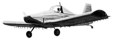
In 1949-50 the Texas A&M College in the USA developed a concept aircraft, the first purpose built agricultural aircraft designed by Fred E Weick and Hugh DeHaven, designated Ag 1 which flew in January 1950, piloted by Ted von Rosenberg. It was a low wing monoplane of all metal construction, powered by a 225 hp piston engine and designed to carry a chemical load of 1,200 lb (544 kg).
Weick Ag-1 N222
Built with US government support, the Ag 1 N222 was demon¬strated widely throughout the USA and was well received by the six or seven hundred pilots who flew it. The main criticism was that it was underpowered, and a decision was taken to refit it with a 300 hp engine. Before this could be done the Ag 1 collided with a powerline pole and ended up on its back. But the crash demonstrated one of the qualities for which it was designed: the aircraft was destroyed except for the cockpit area, but the pilot was uninjured, even though he had been subjected to forces more than 25 times that of gravity, according to the dynamometers installed for test purposes.
The 1933 Teston Low-Wing, N11552 c/n R-1, was a two place, open cockpit, low wing monoplane, built in Georgia, USA. The only one built was powered by a 95hp Cirrus Mk III.
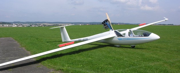
TST-14 Bonus is designed mainly for leisure thermal flights. Its performance is comparable to common two-seat gliders. The wheels on the wing ends allow for independent taxiing and take off.
The major advantage of the TST-14 is the possible and easy installation of the power unit in order to upgrade to the TST-14M. Bonus is equipped with complete duplicate controls and avionics. These make it suitable for flying schools that provide training on motorless and motorized gliders. Aerotow capable
Instrumentation of the TST-14 Bonus glider is fully optional – the customer can either choose instruments from our list of avionics manufacturers or he/she can supply the instrumentation himself/herself during the production of the ordered aircraft. The Bonus can be delivered with an entire range of accessories and a trailer.
Since the completion and testing of the first prototype in 2005, we have sold 10 Bonus gliders to pilots in seven countries. There is greater demand for the TST-14M model, which is the version with the engine installed.
The TST-14 is a tandem two-seat, mid-winged monoplane with a cantilever wing, T-shaped tail and two-wheel tandem undercarriage. Its composite structure is made in negative molds. The wings with sandwich structure is equipped with ailerons and air brakes on the upper surface. There are no ribs in the wing. The strength system of the wing is formed by the main spar, by the aileron spar and by the root rib. All the wing profile of the sandwich structure forms the torsion box.
The wings are interconnected by fittings and two horizontal pins. The connection wing-fuselage is made by means of pins and fittings placed in the fuselage and the wing root rib. The composite ailerons are hung by four hinges with the turning axis on the upper side. Air brakes on the upper side of the wing are made of aluminium and are retracted into pits.
The fuselage with a shell structure is made in the negative mould together with the fin. The tail is a T-shaped sandwich structure. The controls, enabling pitch, roll, air brake and trim controlling, are of the lever design, with a push-pull rods system. The relevant backstops are placed on the stick. The yaw control with adjustable pedals is transmitted by cables. The airplane can be trimmed by a torsional member in the elevator drive that is controlled by a lever in the left of the front cockpit. The undercarriage consists of one unsprung main wheel 350×100 mm and one fixed front wheel. The brake handle is on the left side of the floor. The tail wheel 80×30 mm is turnable.
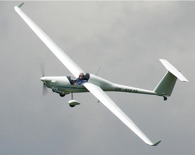
TST-14M Bonus is a two-seat motorized composite ultralight self-launcher with a retractable power unit, suitable for thermal flying, long wave or ridge flights and for flying schools. The aircraft also offers easy handling and the capability of independent take off. TST-14M Bonus is designed mainly for leisure thermal flights. Its performance is comparable to common two-seat gliders. The plane is equipped with a retractable power unit enabling independent take off and reach of an airfield without any thermal support. Engine extraction and retraction is fully automatic and is controlled by electronic servo motors. The power unit is operated by the pilot using two buttons on the instrument panel. The handling of a landed Bonus is very easy thanks to its weight. The wheels on wing ends allow for independent rolling and take off. Production commenced in 2004.
Steve Meassick, a dealer of TeST gliders in the USA, has successfully finalized the certification of the two-seater self-launcher TST-14M Bonus in the LSA category.
TST-14 Bonus M
The Bonus glider can also be delivered in a motorless version (type TST-14), ready for possible future engine installation. Since the completion and testing of the first prototype in 2005, Test have sold 18 Bonus gliders to pilots in seven countries.
With a 17 meter wing span, complete duplicate controls and the ability to extract and retract the engine anytime during the flight, up to 150 km range is possible with the Rotax 503 engine engaged. The TST-14M is still aerotow capable. The Rotax 503 has two carburetors and reducer B, ratio 1:2. An electric starter is standard. The propeller is wooden, two-bladed with fixed adjustment; diameter 1200 mm.
The TST-10 ATLAS, TST-13 JUNIOR and TST-14 BONUS – formed the core of the 2009 production program and have brought a great deal of commercial success.
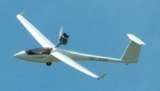
The TST-14J BonusJet is a two seat, high performance, self-launching, jet powered sailplane. Featuring a PBS TJ-100 turbine engine on a retractable pod, it is capable of self launching, cross country soaring and cruising flight.
TST-14J BonusJet
Phase one flight tests have been completed. All systems are functioning perfectly. Initial flight tests show a climb rate in excess of 900 ft/minute.
TST-14 Bonus Wing span: 17 m Wing area: 12.01 sq.m Aspect ratio: 24 Length: 8.24 m Seats: 2 MTOW without BRS: 450 kg MTOW with BRS: 472.5 kg Weight of crew: 65 – 180 kg Vne: 205 km/h Max. maneuvering speed: 150 km/h Max. speed with extended air brakes: 150 km/h Max. speed in aerotow: 150 km/h Stall speed: 65 km/h Max. theor. glide ratio without winglets: 37 by 105 km/h Max. glide ratio with winglets: 39 by 105 km/h Min sink rate: 0,65 m/s at 85 km/h Max. permitted load factor: +4 / -2 Max. calculated load factor: +5.2 / -2.6
TST-14M Bonus Wing Span: 12m Wing Area: 12.01sq.m Aspect ratio: 24 Length: 8.24 m Empty Weight: 472kg MTOW without BRS: 450 kg MTOW with BRS: 472 kg Weight of crew and fuel: 65 – 188 kg Structure: all-composite Seats: 2 Vne: 205 km/h Max. maneuvering speed: 150 km/h Max. speed with extended air brakes: 150 km/h Max. speed in aerotow: 150 km/h Stall speed: 65 km/h Max. theor. glide ratio without winglets: 37 at 105 km/h Max. glide ratio with winglets: 39 at 105 km/h Min. sink rate: 0,65 m/s at 85 km/h Max. permitted load factor: +4 / -2 Max. calculated load factor: +5.2 / -2.6 Engine: Rotax 503, 34 kW (46 HP) Reducer: 1:2 Propeller: Wooden, 1200mm Fuel tank capacity: 30 liters Fuel consumption when climbing: 11 liters / h Fuel consumption at cruising speed: 9 liters / h
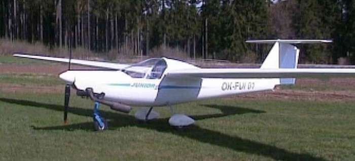
TST-13 Junior 2005is a single-seat ultralight composite glider with an engine installed in the front part of the fuselage and all-composite successor to the TST-9. The aircraft is suitable for tourist flights and leisure thermal flying. The goal of the development work on the TST-13 was to design an ultralight aircraft for pleasurable flying and to feature aerodynamics to allow utilization of thermal conditions for gliding and motorless flights. The concept of the TST-13 is based on the high-performance TST-10 Atlas glider. We used the same wing span of 15m and the fuselage of the TST-10 was modified to enable the installation of the propulsion unit with a thrust propeller in the front part of the fuselage. The fuselage of the TST-13 features an instrumentation panel and design conforming to the category of ultralight motorless aircraft. The landing gear is fitted with two wheels with a controlled tailwheel.
To improve the aerodynamic performance, the aircraft can be equipped with a propeller that is adjustable during flight, including flag positioning. Instrumentation for the TST-13 Junior glider is fully optional – the customer can either choose instruments from our list of avionics manufacturers or he/she can supply the instrumentation himself/herself during the production of the ordered aircraft.
The power unit cab be either Rotax 447 or 503, fitted with a wooden, two-bladed, ground adjustable propeller, dia 1600 mm. Alternatively, propeller SPORTPROP adjustable to a flag position for soaring.Fuel tanks provide for powered flights longer then 6 hours TST-13 is a one-seated, mid-winged monoplane with a cantilever wing, T-shaped tail and two-wheel undercarriage. Its composite structure is made in negative moulds. The wings with sandwich structure are equipped with ailerons and air brakes on the upper surface. The strength system of the wing is formed by the main spar, by the aileron spar and by the root rib. All the wing profile of the sandwich structure forms the torsion box. The wings are interconnected by fittings and two horizontal pins. The connection wing-fuselage is made by means of pins and fittings placed in the fuselage and the wing root rib. The composite ailerons are hung by four hinges with the turning axis on the upper side. Air brakes on the upper side of the wing are made of aluminium and are retracted into pits. The fuselage with a shell structure is made in the negative mould together with the fin. The tail is a T-shaped sandwich structure. The controls, enabling pitch, roll, air brake and trim controlling, are of the lever design, with a push-pull rods system. The relevant backstops are placed on the stick. The yaw control with adjustable pedals is transmitted by cables. The airplane can be trimmed by a torsional member in the elevator drive that is controlled by a lever. The main landing gear with two wheels (300 x 100 mm) is housed in a flexible dural leg. The lever placed on the stick controls the brake. The tail landing gear is provided with turnable tail wheel (120 x 30 mm). The TST-10 ATLAS, TST-13 JUNIOR and TST-14 BONUS – formed the core of the 2009 production program and have brought a great deal of commercial success.
TST-13 Wing span: 15 m Wing area: 10.03 sq.m Aspect ratio: 22.8 Length: 7.45 m Seats: 1 MTOW without BRS: 300 kg MTOW with BRS: 322.5 kg Weight of pilot and fuel: 65 – 122.5 kg Vne: 200 km/h Max. maneuvering speed: 140 km/h Max. speed with extended air brakes: 140 km/h Max. speed in aerotow: 140 km/h Stall speed: 65 km/h Cruise speed: 120-160 km/h Max. glide ratio: 24-32 at 93 km/h Max. permitted load factor: +4 / -2 Max. calculated load factor: +4.8 / -2.8 Engine: Rotax 447 or Rotax 503 Reducer: 1:2 Propeller: Wooden, 1600mm Fuel tank capacity: 40 liters Fuel consumption when climbing: 11 liters / h Fuel consumption at cruise speed: 9 liters / h Seats: 1
TST-10 Atlas is a single-seat motorless composite ultralight glider with optional engine installation, designed mainly for performance thermal flights and wave and ridge flying. Its performance parameters are comparable to common gliders within the standard class. Its weight allows for very easy handling when landed during assembly or disassembly.
The major advantage of the TST-10 is the possible and easy installation of the power unit in order to upgrade to the TST-10M. TST-10 Atlas M is a self-launching UL glider with electric retractable power plant controlled by electronic system. 2009 Price: 22900 EURO
Instruments of the TST-10 Atlas glider are fully optional – the customer can either choose instruments from our list of avionics manufacturers or he/she can supply the instrumentation himself/herself during the production of the ordered aircraft. The Atlas can be delivered with an entire range of accessories and a trailer. The flight characteristics, the quality of design, the wide range of instrumentation offered as well as the reliable power unit are key reasons for the popularity and commercial success of the glider. Since the completion and testing of the first prototype in 2004, 10 Atlas gliders have sold to pilots in seven countries. There is greater demand for the TST-10M model.
The TST-10 Atlas has a 15 meter wing span, all-composite structure, aerotow capable, and Club class conformant. The TST-10 is a single-seat, mid-winged monoplane with a cantilever wing, T-shaped sandwich structure tail and a classical one-wheel undercarriage. Its composite structure is made in negative molds together with the fin.
The wings with sandwich structure are equipped with ailerons and air brakes on the upper surface. There are no ribs in the wing. The strength system of the wing is formed by the main spar, by the aileron spar and by the root rib. All the wing profile of the sandwich structure forms the torsion box.
The wings are interconnected by fittings and two horizontal pins. The connection wing-fuselage is made by means of pins and fittings placed in the fuselage and the wing root rib. The composite ailerons are hung by four hinges with the turning axis on the upper side. Air brakes on the upper side of the wing are made of aluminium and are retracted into pits.
The controls, enabling pitch, roll, air brake and trim controlling, are of the lever design, with a push-pull rods system. The relevant backstops are placed on the stick. The yaw control with adjustable pedals is transmitted by cables. The airplane can be trimmed by a torsional member in the elevator drive that is controlled by a lever in the left of the cockpit.
The undercarriage consists of one unsprung wheel 300×100 mm mounted in a flexible fork. The brake handle is on the control stick. The wingtip wheels serve for independent taxiing and take-off. The turnable tail wheel 80×30 mm enables easy manipulation on ground.
TST-10M Atlas is a single-seat self-launcher with a retractable Rotax 447 power unit, suitable for thermal flights and long wave or ridge flights. The TST-10M can extract and retract the engine anytime during flight. The aircraft also offers easy handling and the capability of independent take off. TST-10M Atlas offers comparable performance to other gliders in the standard class and is equipped with a retractable power unit allowing for independent take off and reach of an airfield without thermal support. Engine extraction and retraction is fully automatic and it is controlled by two electronic servo motors. The power unit is operated by the pilot with two push buttons on the instrument panel. The handling of a landed Atlas is very easy thanks to its weight. The wheels on wing ends allow for independent rolling and take off.
Instrumentation of the TST-10M Atlas glider is fully optional – the customer can either choose instruments from our list of avionics manufacturers or he/she can supply the instrumentation himself/herself during the production of the ordered aircraft. The Atlas can be delivered with an entire range of accessories and a trailer. Aerotow capable and Club class conformant, up to 150 km range is available with the engine engaged.
Since the completion and testing of the first prototype in 2004, Test have sold 25 Atlas gliders to pilots in seven countries.
The Rotax 447 has two separate membrane carburetors and belt reducer, ratio 1:2. Electric starter and the propeller is wooden, two-bladed with fixed adjustment; diameter 1200 mm. The power plant is extracted by a 12V DC servo motor. The servo motor also ensures automatic opening and closing of the engine door in the aircraft fuselage and controls the locking pin, which balances the propeller into a horizontal position prior to engine retraction. The retractable mechanism is handled inside the cockpit through the instrument panel. The pilot controls the extracting and retracting of the power unit with two push buttons on the instrument panel. The very movement is ensured by an electronic unit controlled by a microprocessor, which takes care of the automatic opening of the engine door, monitors the limit position of the power unit, signals the pilot about the exact situation and activity and connects the starter only in the fully extracted position. This electronic system also prevents any retraction of a running engine. Entire engine extraction/retraction lasts approximately 20 seconds. The retractable mechanism of the power unit enables self-launching and restart during flight.
TST-10M Atlas
In 2007 a development of TST 10 MB has started. The first prototype of this modified version was finished in the spring of 2008 and after series of functionality tests a regular production has begin. Five of these motorized gliders are flying in the Czech Republic and France.
TST-10MB was developed from its predecessor, the TST-10M. As a standard the MB version is equipped with electronic servo motor, which is operated by two ways switch for retracting and extracting. This switch is equipped with safety lock for protection against accidental activation. The extracted position of undercarriage is signalized by green light and retracted position is signalized by red light on instrument panel. For higher level of safety, the unit is equipped with acoustic signal, which informs pilot about retracted undercarriage if air brakes are operated.
In case of electricity problems or empty battery, the pilot has also the possibility to extract the undercarriage by hand operated lever for safe landing. Thanks to retractable undercarriage the glide ratio was increased by one point.
Automatic connection of controls for wing to fuselage assembly simplifies the assembling of aircraft, abbreviates time of preparing before fly and it is contributing to the comfort of operation. Wings are simply joined with fuselage through root pins and controls of air brakes and ailerons are connected simultaneously and automatically, without any further adjustment. Assembling person has to install and secure only two main pins of wings.
A new seat base shape has achieved larger space above a pilot´s head, more comfortable sitting in cockpit and usability for taller people. New design of controls paths enabled an increase of fuel tank capacity up to 20 liters / usable, and reshaping of winglets, an experimentally verified position of zig-zag tapes and eddy generators, have contributed to the increasing of glide ratio by one point.
Up to 250 km range with the engine engaged is possible. The undercarriage consists of one unsprung wheel 300×100 mm, which is fully automatically retracted with the use of electric motor. The brake handle is on the control stick. The wingtip wheels serve for independent taxiing and take-off. The turnable tail wheel 80×30 mm enables easy manipulation on ground.
The retractable mechanism is handled inside the cockpit through the instrument panel. The pilot controls the extracting and retracting of the power unit with two push buttons on the instrument panel. The very movement is ensured by an electronic unit controlled by a microprocessor, which takes care of the automatic opening of the engine door, monitors the limit position of the power unit, signals the pilot about the exact situation and activity and connects the starter only in the fully extracted position. This electronic system also prevents any retraction of a running engine. Entire engine extraction/retraction lasts approximately 20 seconds. The retractable mechanism of the power unit enables self-launching and restart during flight.
The TST-10 ATLAS, TST-13 JUNIOR and TST-14 BONUS – formed the core of the 2009 production program and have brought a great deal of commercial success.
TST-10 Wing span: 15 m Wing area: 9.85 sq.m Aspect ratio: 22.8 Length: 6.87 m Seats: 1 MTOW without BRS: 300 kg MTOW with BRS: 322.5 kg Weight of the pilot: 65 – 115.5 kg Vne: 180 km/h Max. maneuvering speed: 140 km/h Max. speed with extended air brakes: 140 km/h Max. speed in aerotow: 140 km/h Stall speed: 60 km/h Max. theor. glide ratio without winglets: 38 at 88 km/h Max. glide ratio with winglets: 40 at 88 km/h Min sink rate: 0,62 m/s at 72 km/h Max permitted load factor: +4 / -2 Max calculated load factor: +5.26 / -3.26
TST-10M Atlas Wing Span: 15m Wing Area: 9.85sq.m Empty Weight: 322.5kg Aspect ratio: 22.8 Structure: all-composite Engine: Rotax 447 L/DMax: 40 at 88 km/h MinSink: 0,62 m/s at 72 km/h Seats: 1 Length: 6.87 m MTOW without BRS: 300 kg MTOW with BRS: 322.5 kg Weight of the pilot and fuel: 65 – 115.5 kg Vne: 180 km/h Max. maneuvering speed: 140 km/h Max. speed with extended air brakes: 140 km/h Max. speed in aerotow: 140 km/h Stall speed: 60 km/h Max. theor. glide ratio without winglets: 38 at 88 km/h Max permitted load factor: +4 / -2 Max calculated load factor: +5.26 / -3.26 Engine: Rotax 447, 29.5 kW (40 HP) Reducer: Belt 1:2 Propeller: Wooden, 1200mm Fuel tank capacity: 14 liters Fuel consumption when climbing: 11 liters / h Fuel consumption at cruise speed: 9 liters / h
TST-10MB Atlas Wing span: 15 m Wing area: 9.85 sq.m Aspect ratio: 22.8 Length: 6.87 m Seats: 1 MTOW without BRS: 300 kg MTOW with BRS: 322.5 kg Weight of the pilot and fuel: 65 – 115.5 kg Vne: 180 km/h Max. maneuvering speed: 140 km/h Max. speed with extended air brakes: 140 km/h Max. speed in aerotow: 140 km/h Stall speed: 60 km/h Max. theor. glide ratio without winglets: 38 at 88 km/h Max. glide ratio with winglets: 42 at 88 km/h Min sink rate: 0,62 m/s at 72 km/h Max permitted load factor: +4 / -2 Max calculated load factor: +5.26 / -3.26 Engine: Rotax 447, 29.5 kW (40 HP) Reducer: Belt 1:2 Propeller: Wooden, 1200mm Fuel tank capacity: 20 liters Fuel consumption when climbing: 11 liters / h Fuel consumption at cruise speed: 9 liters / h