Travel Air built some efficient monoplanes, including the Woolaroc that obvious imitation of Lindbergh’s Ryan with which Art Goebel won the doleful Dole Derby race to Honolulu.
Monoplane
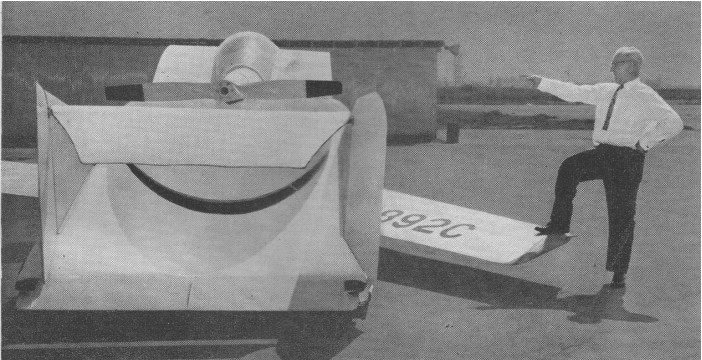
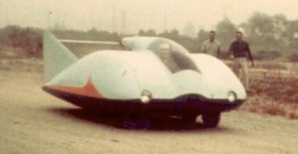
Trautman Roadair
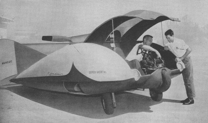
This Road Air was the first prototype, and last production model built by Herbert Trautman. The idea of making a car that could fly had always been a fascination for Herb. The idea for a plane/car combination was first conceived of in the aviation pioneer days prior to World War I but technical limitations of the time prevented any serious progress to be made. Interest was rekindled in the late 1920’s when ideas and activity flourished. It first flew in 1946. By 1950, Herb Trautmann had begun construction of the Road Airand, Herb continued to build his dream car until it was completed in 1959.
After finishing his dream flying car, Herb was ready for his maiden flight. Herb climbed in, locked the hatch, started the Road Air and began to taxi. Feeling comfortable he began to get the feel of the Road Air on faster and faster runs. Finally, he lined up into the wind, applied full power and headed down the runway. At about 90 mph the Road Air lifted off the ground to about 3 feet. As Herb soon began to loose control, he set the Road Air back on the runway averting disaster. He put it in storage, never to be flown again.
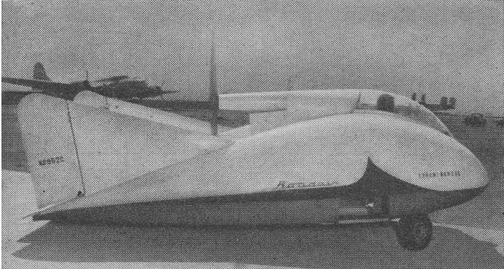
Called the Roadair, the car has a body 15 feet long and 7 feet 10 inches wide. As an auto, it rides on a tricycle gear, the single rear wheel driven by a small gasoline motor. As an airplane, the wings fold out from the body to a 25 foot wingspread. A 75-horsepower airplane engine drives the single pusher propeller. Twin rudders and elevator are located in the rear. Expected retail price was approximately $10,000.
Estimated cruising speeds are 90 miles per hour in air and up to 75 on ground. FAA experimental license has been issued. Roadair operates us auto or plane from same controls. Same action moves rudders and wheels. Wings fold up inside body.
When Kermit purchased the Tallmantz Collection in 1985 the Road Air was on loan for display by Mr. Trautmann. When packing the collection for shipment to Florida, Herb, in his eighties, came out for a visit to decide what to do with his aircraft. He had no place to store it and when Kermit offered to take it back to Florida, Mr. Trautman signed over a Bill of Sale and gave it to him on the spot.
In 1996 the Road Air was restored to run-able condition. It is sometimes taken by trailer to trade shows and events as an attention getter to help promote Fantasy of Flight. On one promotional outing, the Road Air was taken down to the local U.S.A. Speedway and driven around the track for a quick demonstration.
Engine: 85 hp Continental
Wingspan: 25′
Gross Weight: 1,000 lbs
Transland Ag-2
The idea of an agricultural aircraft followed a meeting between George Wing, Lloyd Stearman, Tom Watson (from Aerial Agriculture in Sydney, Australia) and George Roth (of Murryair of Hawaii and later owner/producer of Eniroth). George Roth had been instrumental in the building of the Ag-1, and he was an obvious influence in the Ag-2 design by George Wing’s team.
Construction of the first aircraft began in 1954 and the Transland Ag-2 made its first flight from Torrance as N8330H on 11 October 1956. At that stage, it was a single-seat aircraft powered by a 450-hp Pratt & Whitney R-985. Between the engine and the cockpit was housed an integral hopper of 53 cubic feet intended for solid materials and carrying a load of 3,000 lbs in the restricted category. The length of the cropduster was 28 ft, 5 inches and its height 9 ft. 8 inches.
The centre wing was built in two sections fastened to the fuselage either side of the hopper. Each section incorporated two 62.5 US gallon tanks which were intended as spray tanks totalling 250 US gallons. The wing was extremely thick – some eighteen inches deep – which gave high lift but also high drag. The aerofoil, a modified NACA 64021 section, had an aspect ratio of around 21%. A single flap extended under the fuselage between both sections. The outer wing panels also incorporated a 62.5 US gallon tank intended for aircraft fuel. The ailerons ran the full length of these panels with a top side lifting flap, which presumably kept a clean airflow over the wing and ailerons. Aluminium wing tips gave a wing span of 42 ft and a wing area of 321.6 sq.ft.
While the test flying was done on the first aircraft, a second, N8331H, was built and fitted with a 600-hp P&W R-1340. The payload was increased from 2,000 lbs to 3,000 lbs, giving an all-up weight in the agricultural category of 7,700 lbs. The empty weight of the aircraft was 3468 lbs.
N8331H first flew from Torrance in June 1958. The first aircraft was also retrofitted with an R-1340 and the rear
cockpit modified to carry a passenger. The then Civil Aero¬nautics Administration awarded Type Certificate #4A20 to Transland Aircraft for the Ag-2 on 24 June 1958.
In 1959, a third and final aircraft, N8232H, was built and operated in Panama.
The monocoque design of the Ag-2 didn’t fail, it was twenty years ahead of its time. In the 1950s and ‘60s, the Stearmans and the Naval Aircraft N3Ns were still the “big planes” of an operator’s fleet and were able to be obtained cheaply for US$5,000, as opposed to the Ag-2’s price tag of US$25,000.
With 577 hours on the clock, N8330H was sold to Charles Chalking in Uruguay in 1962. The aircraft was flown to the South American country, where it was registered CX-AYC in May 1962. Under the name of Azucarera del Litorial SA of Paysandu, it flew some 224 hours on sugar fertilizing until 31 December 1963, when it was placed in storage. The aircraft spent 28 years in storage before being sold to an operator at Triente y Tres. Flown again on 25 September 1991, the Ag-2 had clocked up another 290 hours by 23 February 1993 before it was parked up at the airfield at Triente y Tres for seven years. Around 2000 the wings were removed and stored in a shed, while the fuselage was pushed to the edge of the airfield where weeds began to incarcerate it. In April 2003 the aircraft arrived in New Zealand for restoration, with 1091.2 flying hours. At some early stage the inside of the hopper was lined with fibreglass.
Engine: Pratt & Whitney R-985, 450-hp
Seats: 1
Length: 28 ft 5 in
Height: 9 ft. 8 in
Hopper cap: 53 cubic feet
Load cap: 2,000 lbs
Spary tank cap: 250 USG
Fuel cap: 62.5 USG
Wing span: 42 ft
Wing area: 321.6 sq.ft
Engine: Pratt & Whitney R-¬1340, 600-hp
Seats: 2
Payload: 3,000 lb
MAUW: 7,700 lb
Empty wt: 3468 lb
Model 2 / 1-G
The Transcendental Aircraft Corporation of Glen Riddle, Pennsylvania, was the first company to claim flying a successful Tilt Rotor aircraft. The Model 1-G was a small, high-wing experimental aircraft with a fuselage-mounted engine and fixed tricycle landing gear designed and built by Mario A. Guerierri. The single pilot sat forward of the wing in a semi-enclosed fuselage. The clear plastic nose gave the pilot helicopter-like visibility. A single Lycoming 0-290-A six cylinder engine produced 160 horsepower. The fuselage measured 7.9m long, and the aluminum wing measured 6.4m. The ailerons were fabric covered. Empty weight was 655kg and take-off weight was 790kg. The projected maximum speed in helicopter mode was 190km/h, and 260km/h in airplane mode.
A 5.2-meter diameter, three-bladed, fully articulated rotor was mounted at each wing tip. The rotor shafts tilted from pointing vertically for hover down to 6 degrees up from horizontal for forward flight. Electric motors controlled the tilt of the rotor shafts.
Interconnecting shafts ensured that both rotors maintained the same tilt angle. Each rotor was driven through a two-speed gearbox. This allowed the pilot to lower the rotor rotation speed for more efficient cruise in forward flight.
Although the Model 1-G was a private development, the Wright Air Development Center at Wright-Patterson AFB issued contracts to study many of the Tilt Rotor’s unique peculiarities.
The first was awarded in 1952 to investigate the dynamics and structural characteristics of the rotor system. The Air Force awarded a second contract in 1953 to investigate mechanical instability problems associated with tilting the rotors.
The first hover flight was either on June 15 or July 6, 1954 (references vary). The first forward flight in hover mode occurred on December 13, 1954, and the first forward flight with rotors tilted occurred only four days later. By April 1955, conversions with the rotors tilted up to 35 degrees from vertical were completed. Eventually, the Model 1-G completed numerous transitions up to 70 degrees of tilt with the wings sustaining over 90 percent of the weight.
The engine reduction was been replaced by a two-gear reduction box, at the exit of which a gearing system has been attached which enables the rotors to be put into auto-rotation. At the engine’s maximum output of 3000 r.p.m. the rotors rotate at 633 r.p.m. as airscrews, and at 240 r.p.m. as helicopter rotors.
Three concentric tubes start from the swivelling device, the first of which moves the rotor, the second controls cyclic variation and the third variation of collective pitch. The time needed to move from the helicopter to the aircraft position is roughly three minutes. In this change-over, the rotors swivel through an angle of 82 degrees.
The Model 1-G was destroyed during a test flight on July 20, 1955. After performing a virtually complete conversion, the friction lock on the collective pitch controller slipped, throwing the aircraft into an abrupt, steep dive. The pilot initiated a recovery, but there was not enough altitude to complete the pull-up before contacting the Delaware River. The aircraft flipped on its back, resulting in irreparable damage.
During the Model 1-G’s brief career, it made over 100 flights, achieved 90% conversion (about 70 degrees forward rotor tilt), and flew 60 hours. It demonstrated excellent controllability without vibration, and reached an altitude of 1060m and an airspeed of 185km/h in helicopter mode.
A second aircraft, called the Model 2, N546A, was to fly in late 1956. Transcendental received an Air Force contract in March 1956 and completed the Model 2 in October. Compared to the Model 1-G, it was stronger and more aerodynamic, but had the same basic configuration. The enclosed cockpit had side-by-side seating. Power was by one 250 horsepower Lycoming O-435-23 six cylinder engine. The wing was a 0.3m longer, but the fuselage was 1.2m shorter. Empty and gross weights were 708kg and 1015kg. Development ended when funding from Wright Air Development Center stopped. It could not be determined if the aircraft ever flew, and eventually it was dismantled.
The Model 3 of 1957 was also a convertible, and an extrapolation of Model 1G, it is intended to be powered by two gas turbines, and to accommodate a crew of two and also six passengers or alternatively four stretchers. It is expected that this model will have a cruising speed comparable to that of a traditional aircraft and also the special take-off and landing properties of a helicopter.
Model 1G
Engine: 1 x Lycoming G0-290-A, 160hp
Rotor diameter: 5.18m / 17 ft
Width (rotor tip to rotor tip): 11.58m
Rotors: 2 x 3-blade on outriggers
Max rotor speed: 633rpm
Wing span: 21 ft
Length: 7.93m / 26′ 0″
Height: 2.13m
Weight fully loaded: 794kg / 1,640 lb
Empty weight: 658kg
Maximum speed (as helicopter): 196km/h
Maximum speed (as aircraft): 256km/h / 150 mph
Absolute ceiling (as aircraft): 1525m
Endurance: 90 minutes
Seats: 1
Model 2
Engine: Lycoming O-435-23, 250hp
Wingspan: 22’9″
Length: 22’1″
Rotor dia: 18’0″
Useful load: 670 lb
Seats: 2
Transavia PL12 Airtruk
Designed in Australia by Luigi Pellarini and first flown on 22 April 1965, as a liquid chemical sprayer, the Airtruk can carry up to 180 Imp gallons (818 litres) and can dispense chemical over a swath width of 100ft (30.2m). First powered by a 285 hp engine, later models were fitted with the 300 hp Continental IO-520-F. The PL-12 entered production by Transavia Corporation in Australia in 1966.
Around 120 were made in the 23 years from its first flight in April 1965. Transfield manufactured the wholly-Australian designed multi-purpose aircraft for over twenty years. Initially designed as a specialised agricultural aircraft, it was refined over the years and used for many purposes including military surveillance and medivac roles in the PL-12-U utility version.
The last planes built by Transfield were made up of spare parts from many of the 117 planes produced at the company’s Seven Hills, Australia, workshop. Many were exported to countries such as Denmark, Yugoslavia, Spain, Africa, China and New Zealand.
Flight Engineers Ltd was a joint company formed by agricultural operator Barr Brothers and Marine Helicopters Ltd. to maintain own fleets, but also undertook license-assembly of Transavia PL-12 Airtruk agricultural aircraft from 1973.
The T-320 model were assembled in Auckland, New Zealand. They featured increased side and head room, electric flaps and new ailerons. T320 version powered by Continental Tiara engine introduced 1977. Production ended 1980.
Transavia PL12 Airtruk
Engine: One 285HP Rolls Royce Continental IO-520-A
Wing span: 12.15 metres (39 ft 10 in)
Length: 6.35 metres (20 ft 10 in)
Accommodation: One pilot – 2 pax
Hopper capacity: 180 ImpGal / 818 lt
PL-12-U
Engine: Continental IO-520-D, 300 hp
Wingspan: 39 ft 10.5 in / 12.15 m
Length: 20 ft 10 in / 6.35 m
Empty weight: 1830 lb / 830 kg
MTOW: 3800 lb / 1723 kg
Max cruise 75% SL: 102 kt / 117 mph
ROC: 800 fpm / 244 m/min
Service ceiling: 10,500 ft / 3200 m
Range max payload: 650 nm / 749 mi / 1203 km
Crew: 1
Passengers: 1 on upper deck / 4 on lower deck
Passenger cabin length: 9 ft 0 in / 2.74 m
Passenger cabin width: 3 ft 2 in / 0.97 m
Passenger cabin height: 8 ft 11 in / 2.11 m
Passenger cabin volume: 74 cu.ft / 2.10 cu.m
PL 12
Engine: Continental IO 520 D, 300 hp
Prop: 7 ft 4 in (2.23 m) dia 2 blade
Wing span: 39 ft 10.5 in (12.15 m)
Length: 21 ft 0in (6.40 m)
Height: 2.79 m
Wing area: 256 sq ft (23.79 sq.m)
Gross weight: 4,090 lb (1,855 kg)
Max cruising speed: 121 mph (195 kph)
Maximum speed: 208 km/h
Ceiling: 10,500 ft
Max range: 380 miles (610 km)
Accommodation: Crew of 1 and 2 pas¬sengers.
PL12-T300
Engine: Lycoming IO-540-K1A5, 300 hp
Prop: Hartzell 3 blade, 84in
PL12-T320
Engine: 1 x RR/Continental Tiara 6-320B
Transall C-160
The association between France and Germany that has produced the Transall began when the German aircraft industry built the Nord 2501 Noratlas under licence for the Luftwaffe. The successful co-operation between the Weserflugzeugbau GmbH and Nord Aviation on the Noratlas programme led to both companies studying a follow-on project for this old-fashioned twin-boom piston-powered medium transport. The “Transporter-Allianz” was formed in January 1958 by the participating companies, Transall being an abbreviation of the name, while the letter “C” stood for “Cargo” and the figure “160” for the equivalent wing area of 160 square metres. The joint team designed a tactical cargo and troop transport in the 50-ton category to fulfil the joint requirements of the French and German forces, with the capability of hauling a 17,600-1b (8 000-kg) payload out of semi-prepared fields over a radius of 750 miles (1200 km) without refuelling.
After several individual concepts had been studied separately in both countries, the Transporter Allianz concentrated on a shoulder wing design with two Rolls-Royce Tyne 20 Mk 22 turboprops of 6,100 eshp each, with a rear loading ramp and a kneeling landing gear to lower the fuselage for loading. According to the bi-national contracts signed in December 1959 and March 1960, the R & D costs were to be divided equally between France and the Federal Republic of Germany while each country would pay for the number of aircraft ordered for its specific needs, and final assembly lines would be established in each country.
The first prototype, the C-160 V 1, was assembled in France and made its maiden flight on 25 February 1963 at Villaroche, the V2, assembled by VFW Fokker, following exactly three months later at Lernwerder; the V3 flew on 19 February 1964 in Hamburg, (two separate assembly lines having been set up in Germany by MBB and VFW). Also in 1964, the airframes for static and dynamic tests were completed. An additional six pre-series aircraft were built before production started, with the first delivery on 2 August 1967. France had meanwhile ordered 50 Transalls (C- 1 60F), Germany ordered 110 (C-160D), 20 of these being later passed to the Turkish Air Force (as C-160T), and the Republic of South Africa bought another nine (C-160Z). The six pre-series aircraft were divided between France and Germany.
As far as the production breakdown is concerned, Nord Aviation was responsible for the wings and engine nacelles, Hamburger Flugzeugbau (HFB) built the front and rear sections of the fuselage and Vereinigte Flugtechnische Werke (VFW) the central fuselage and the horizontal tail surfaces. Some wing parts and the flaps were sub-contracted to Messerschmitt and Siebel ATG while Dornier built the vertical tail surfaces. The Messier-designed landing gear was coproduced with Liebherr-Aerotechnik. Rolls-Royce cooperated with Hispano-Suiza (now a branch of Snecma, France), MAN (later Motoren- und Turbinen-Union, Munich) and FN (Belgium) in manufacturing the Tynes. Ratier-Forest in France produced the big 18-ft (5,49-m) diameter four-bladed de Havilland propellers and Normalair (UK) delivered the pressurisation and air conditioning systems. VFW was the lead company in the programme.
The shape and dimensions of the fuselage were essentially designed to conform with the “International Railway Loading Gauge” over the entire length of the hold. The length of the compartment including the ramp is 56 ft 6 in (17,21 m), the useful width is 10 ft 4 in (3,15 m) and the max useful height 9 ft 9 in (2,98 m). The floor area is 583,9 sq ft (54,25 sq.m), giving a usable volume of 4,940 cu.ft. (140 cu.m).
Thus, a total of 178 Transalls had been produced when the last aeroplane rolled off the assembly line in October 1972. Deliveries totalled 52 C 160F for the Armee de l’Air (four modified as 160P civil night mail transports), 110 160D for the Luftwaffe (20 later transferred to the Turkish air force and 32 stored) and nine 160Z for the South African Air Force.
The Transall C-160 was designed for flexible payload-range capabilities and stringent mission requirements. These include high gust and manoeuvre loads of 3 g at low level, as well as high static loads on landing gear and structure encountered in rough, semi-prepared field operations. The fuselage is built in three units, with the usable section designed for an operating pressure of 4.7 psi. In the centre section of the fuselage, seven main wing-fuselage frames made of forged and plate components carry the loads from the wing and the landing gear. The fuselage skin is stiffened by extruded Z section stringers. Heavy corrugated aft-fuselage frames in the tailplane take up the forces from the tail unit and the aft upward hinged cargo door.
The wing comprises three major components, a parallel chord centre section to which are bolted two tapered outer panels. The primary structure is a wing torsion box with two shear-web spars to which are attached the leading- and trailing-edge sub-assemblies. The upper and lower wing skin panels are stiffened with longitudinal extruded T-section stringers. Double-slotted flaps, spoilers, airbrakes and ailerons make up the moving surfaces of the wing.
The tail unit consists of a three-spar, fully cantilevered horizontal stabiliser and a three-spar fin torsion box with stiffened skin construction. Elevator and rudder are of the same conventional construction. The dorsal fin consists of aluminium sandwich flat panels.
The main landing gear has eight wheels, with two tandem pairs of wheels on each side. Together with low pressure (55 psi) tubeless tyres sized 15.00-16, the resulting single wheel loads provide the aircraft with an excellent ability for operations from semi-prepared or unprepared strips. The twin-wheel low pressure (45 psi) nose gear is hydraulically steerable through 55 deg each side. To ease loading procedures from ground or low levels, the main landing gear may be kneeled, ie, partially retracted, thus changing the ramp slope-angle with respect to the cargo compartment floor-line. The system is operated by special built-in shock absorber-jack cylinders through power supplied by one of the engines, APU or hand pump.
Aerospatiale, MBB and VFW, decided in May 1976 to reinstate the production of the twin-turboprop Transall C-160 tactical transport. The French Armee de l’Air was at that time showing interest in buying 25-30 aircraft, and an industrial agreement was signed on 29 October 1976, it being then estimated that an order backlog of at least 75 aircraft would be needed to make the new programme an economic worthwhile enterprise.
The French Government therefore decided in July 1977 to approve the launching of the second series of the Transall C160 and ordered 25 aircraft for the Armee de l’Air. The only large aeroplane in Europe to be built on a re-established production line, having been designed in the mid-‘fifties.
Under the new industrial agreement for the second series, rather different arrangements have been made, there being no main contractor. Aerospatiale and the two German manufacturers VFW and MBB – all three original members of the Transporter-Allianz having changed their status as a result of mergers in the last decade – share the work on a fifty-fifty basis, now with a single assembly line at Toulouse. Aerospatiale is building the wings, fuselage doors, emergency exits and engine nacelles. The manufacture of the front and rear fuselage sections including the loading ramp and the dorsal fin is undertaken by MBB. VFW (itself now in process of merging with MBB) produces the centre fuselage, main landing gear fairings and all main tail surfaces. Unchanged from the previous arrangement is the share of production of the Tynes, jointly manufactured by Rolls-Royce, Snecma, MTU and FN. As in the Airbus programme, all the major airframe parts are airlifted from the manufacturing centres in Germany to Toulouse in a Super Guppy transport, for final assembly and flight testing.
No major modifications have been incorporated in the C160 design, but the list of changes in many details is quite impressive. The forward side loading door is deleted and the deicing system improved. Minor changes affect the landing gear as well as the cargo handling system. New bonding techniques are applied and corrosion protection is improved. Structural provisions are made for additional fuel tanks in the wing centre section to allow for a total of 6,170 Imp gal (28 050 lt) instead of 4,190 Imp gal (9 050 lt) with the original outer wing tanks only. This not only provides for an extended range of 4,780 nm (8 854 km) for ferry flights, but also sufficient fuel capacity for aerial refuelling tasks which are new for the aircraft. Ten of the 25 new Transalls are to be equipped with hose and drogue in-flight re-fuelling systems in the lengthened port main landing gear fairing, to serve as tankers; another five will have provision for this equipment and can be rapidly adapted to the tanker role if required. All the 25 aircraft can be refuelled in flight, using a 13 ft 1.5 in (4-m) long probe installed above and behind the flight deck.
The flight deck is designed for operations by a crew of three. As an optional extra it accommodates a swivelling seat for special tasks. The exceptionally spacious flight deck also has two berths in addition to the crew seats. The field of vision from the pilot’s position is 243 degrees.
Although the Transall C-160 is specially designed for carrying troops and cargo, it is also capable of fulfilling a variety of other missions. With a maximum payload of 3 5,270 lb (16 000 kg), the range is 1,000 mls (1850 km), increasing to 2,750 mls (5 100 km) for a payload of 17,640 lb (8 000 kg); the maximum range for ferry flights is 4,780 mls (8 850 km). Fuel consumption with both engines operating varies from 2, 100 lb to 2,755 lb (950 kg to 1250 kg) per hr and the manufacturer claims that this figure is about 30 per cent better than its competitors on a given mission.
As a cargo transport, a variety of heavy or outsized loads can be carried. This includes most military vehicles, airmobile tanks, armoured cars, missiles, partially disassembled helicopters and aircraft. An automatic latching system and easily adjustable rails and rollers permit quick-loading of pallets in standard sizes such as 88 in x 125 in (2,24 m x 3,18 m), 88 in x 108 in (2,24 m x 2,74 m), etc, standard inter-model 8 ft x 8 ft (2,44 m x 2,44 m) containers as used on trucks, railways, ships and wide-body aircraft, or 12 LD3 containers. Reinforced vehicle treadways allow for carrying vehicles with axle loads of up to 11,023 lb (5 000 kg) and freight loads of up to 205 lb/sq ft (1000 kg/sq.m). Air dropping of heavy loads (up to 17,640 lb/8000 kg single loads) is possible either by gravity release or parachute extraction.
Deliveries of the Transall C-160 (Second Series), which first flew on April 9, 1981, were completed in 1985. The sole military customer was the French Air Force, which ordered 25 with updated avionics, a strengthened wing centre section incorporating an additional fuel tank, and in-flight refuelling capability. Ten are equipped as dual-role single-point tankers, and five more have the necessary modifications to allow rapid conversion to the tanker role. In 1982 four additional aircraft were ordered for the French Air Force, two as secure communications relay platforms known as C-160A Astarte for the nuclear deterrent force from 1987, and two Gabriel electronic intelligence aircraft.
C.160
Type: tactical transport
Crew: 3
Engines: two 6,l00-ehp (4,549-kW) Rolls-Royce Tyne RTy.20 Mk 22 turboprops
Props: Ratier Forest built BAe Dynamics 4 blade constant speed feathering, reversing, 21 ft 4 in (6,50 m) dia
Maximum speed 319 mph (513 kph) at 16,000 ft (4,875 m)
Cruise speed: 510 kph
Initial climb rate 1,300 ft (396 m) per minute
Single engined climb rate, 300 ft/min (1,51 m/sec)
Service ceiling 27,000 ft (8,230 m)
Single engined ceiling, 10,000 ft (3 050 m)
Range 1,150 miles (1,853 km) with max payload
Range 5100 km with 8,000 kg
Max ferry range, 4,780 nm (8 858 km)
Empty weight 63,935 lb (29,000 kg)
Maximum take-off 112,435 lb (51,000kg)
Wing span 131 ft 3 in (40.00 m)
Length 106 ft 3.5 in (32.4 m)
Height 38 ft 2.75 in (11.65 m)
Undercarriage track, 16 ft 9 in (5,10 m)
Wheelbase, 34 ft 4.5 in (10,48 m)
Wing area 1,722.3 sq ft (160 sq.m)
Payload: 93 troops, or 88 paratroops, or 62 litters and four attendants, or 35,273 lb (16,000 kg) of freight
Air refuel: Yes
T/O run: 715 m
Ldg run: 550 m
Basic fuel capacity, 4,190 Imp gal (19050 lt); optional wing centre section tanks for 1,980 Imp gal (9 000 lt)
C-160 Srs.2
Engines: 2 x Rolls-Royce/Snecma/MTU Tyne RTy 20 Mk 22 turboprops, take-off rating 6,100 eshp each at SL, ISA, and 5,950 eshp at SL, ISA + 22 deg C; water/methanol injection system
Fuel capacity, outer wings only, 4,190 Imp gal (19 050 lt), total with centre wing tanks, 6,170 Imp gal (28 050 lt)
Props: four-bladed Ratier-Forest (under HSD-licence) fully feathering and reversible
Prop diameter, 18 ft 0.5 in (5,50 m)
Garrett AiResearch GTCP 85-160 APU, max continuous rating, 200 shp
Max operating, speed, VMO 277 kts (513 km/h) CAS
MMO, M = 0.64
Initial rate of climb (at 108,355 lb/49 150 kg, SL, ISA); 1,360 ft/min (6,9 m/sec)
Max operating altitude, 30,000 ft (9 145 m)
Take-off run (at 108,355 lb/49 150 kg, SL, ISA), 2,100 ft (6 400 m)
FAR take-off field length, 5,600 ft (1707m)
Landing run (MLW, SL, ISA), 1,400 ft (427 m)
FAR landing field length, 4,950 ft (1509 m)
Max range (at MTOW) including reserves for 5% initial fuel + 30 min: 1,000 nm (1850 km) with max payload of 35,273 lb (16 000 kg), 2,750 nm (5 094 km) with payload of 17,637 lb (8 000 kg)
Max range with outer wing fuel only, 3,430 nm (6 353 km), with centre section tanks, 4,780 nm (8 854 km).
Max take-off weight, 112,434 lb (51000 kg)
Max landing weight, 103,615 lb (47 000 kg)
Max zero fuel weight (2.5 g factor), 99,206 lb (45 000 kg), (3.0 g factor), 81,570 lb (37 000 kg)
Minimum operating weight empty, 61,728 lb (28 000 kg) (plus 440 lb/200 kg for centre wing tanks)
Span, 131 ft 3 in (40,00 m)
Length, 106 ft 3.5 in (32,40 m)
Height, 28 ft 2.5 in (11,65 m)
Wing area, 1,722 sq ft (160,00 sq.m)
Accommodation: Flight crew of three
Cabin floor area, 584 sq ft (54,25 sq.m)
Cabin volume, 4,944 cu ft (140,00 cu.m)
Trago Mills SAH.1 Sprint / Orca Aircraft Ltd SAH-1 / Lovaux / FLS Aerospace Sprint
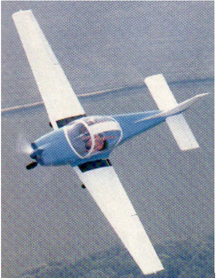
Trago’s boss, supermarket entrepreneur Mike Roberts, claimed to have already spent £1•25 million since he brought in chief designer Sydney Holloway in 1977 to build a trainer aimed at reversing the fortunes of British light aviation.
Holloway started work on the SAH.1 in 1977, build¬ing the aircraft in the living room of his home next to Bodmin airfield. Holloway’s wife Sheina did the drawings and put up with the mess. Holloway’s task was eased by the spon¬taneous help given by several skilled experts including Frank Robertson (no relation to Mike Robertson), who took over responsibility for the aerodynamic and stress calculations.
Holloway went for a strong but simple metal airframe, with the emphasis on minimum maintenance and easy repair. Unproven materials have been avoided, and PVC foam has been used for skin stabilisation to prevent “oil-canning”. The ailerons are of the slot¬ted Frise type, with differential action and external mass-balances. The slotted flaps, operated by means of a lever between the seats, incorporate built-in steps for easy entry.
With a 47 in cockpit, and a 14 cu.ft baggage bay behind the two folding and adjustable seats which can carry l00lb of baggage.
The SAH.1 can carry two l80 lb people and and two 12.5 Imp gal integral wing tanks full. It is cleared for aerobatics and spinning, and is stressed to +6g/-3g.
Orca Aircraft Ltd purchased the SAH-1 trainer from Trago Mills but went into administration in 1989. The SAH-1 became Sprint when purchased by Lovaux / FLS Aerospace. Lovaux Ltd was a subsidiary of FLS Aerospace for aircraft maintenance.
Powerplant: One 118 b.h.p. Avco Lycoming O-235-L2A
Prop: McCauley fixed-pitch, 5ft 6in diameter
Wing span: 30ft 8.4in
Length overall: 2lft 10.25in
Height: 7ft 7.5in
Cockpit length: 5ft
Cockpit width: 3ft 11.5in
Baggage volume: 14 cu.ft
Empty, equipped: 1,l00lb
Max take-off: 1,750lb
Max fuel load 25 Imp gal: 188 lb
Max wing loading: 14.581b/sq.ft
Never exceed: 164kt
Max level speed/sea level: 122kt
Cruise at 75% power/sea level: 110 kt
Service ceiling: 16,400ft
Take-off to 50ft (15 deg flap): 1,285ft
Range with 45mm reserve: 620 n.m.
Trager-Bierens Alibi T-3
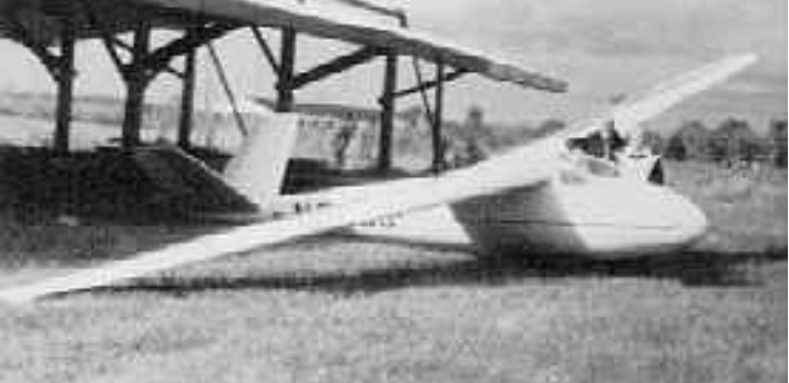
Designed by Kempes Trager and John Bierens, the T-3, which first flew in 1951, uses a set of Laister-Kauffmann LK-10A wings with a new all-metal fuselage with V-tail and retractable wheel. Later the wing was rebuilt and a new all-metal tail was incorporated.
Wing span: 15.24 m / 50 ft
Wing area: 13 sq.m / 140 sq.ft
Aspect ratio: 17
Airfoil: NACA 4418
Empty Weight: 227 kg / 500 lb
Payload: 113 kg / 250 lb
Gross Weight: 340 kg / 750 lb
Wing Load: 26.15 kg/sq.m / 5.1 lb/sq.ft
MinSink: 0.67 m/s / 2.2 fps / 1.30 kt
L/DMax: 28 77 kph / 42 kt / 48 mph
Seats: 1
No. Built: 1
Structure: wood/ fabric wings. Metal fuselage and tail.
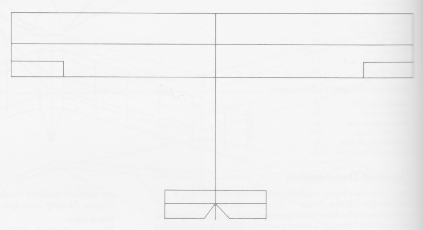
Tradewinds Gliders TW-21
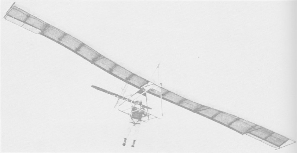
Circa 1972, the TW-21 is a fixed wing that has full three axis control, ailerons, rudder and elevators.
Stressed for 4.5G, all tubing is 6061-T6 seamless aircraft aluminium. Sizes from 5/8in to 1 5/8 in is used. Rigging cable is 3/32in 7×7 and 1 5/8 x .049 is used. All fittings and joints are heli-arc welded.
All bolts, nuts, turnbuckles, pulleys and brackets are aircraft quality. The sail options were 3.0 or 5.8 oz dacron, with a choice of 10 colours. All seams and stress areas are double zig-zag stitched and reinforced.
The TW-21 has fully adjustable seat harness and ground support straps, and an optional prone harness was available.
The control system and control stick are machined steel and welded.
Chord length: 4 ft 9 in
Wing span: 32 ft
Aspect ratio: 6.85
Nose angle: 0˚
Wing area: 153 sq,ft
Weight: 55 lb
Pilot weight: 110-220 lb
Takeoff speed: 12 mph
Stall speed: 14 mph
Max speed: 45 mph
Best glide ratio (L/D): 12:1
Best L/D speed: 26 mph
Min sink: 185 fpm
Chord length: 4 ft 9 in
Wing span: 34 ft
Wing area: 154.5 sq,ft
Aspect ratio: 7.55
Nose angle: 0˚
Weight: 71 lb
Pilot weight: 110-250 lb
Takeoff speed: 12 mph
Stall speed: 14 mph
Max speed: 45 mph
Best glide ratio (L/D): 12:1
Best L/D speed: 26 mph
Min sink: 185 fpm
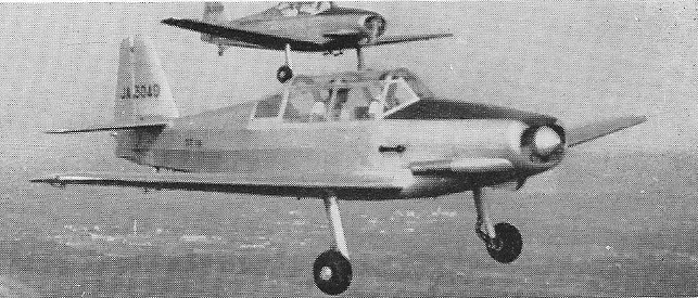
Toyo Aircraft T-T.10
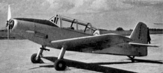
Toyo Aircraft was established in June 1952 and their first aircraft, the T-T.10 designed by Yoshio Hashiguchi, was completed by the end of the year. It is of mixed construction; the wing is built entirely from wood and fabric around two spars, with a plywood skin enclosed within fabric. The flaps and ailerons are wood framed and fabric covered. In planform the wings are straight tapered with rounded tips; most of the taper is on the trailing edge. There is 6 degrees of dihedral. The T-T.10’s tail surfaces are also straight tapered with rounded tips, generally wood framed with fabric covering. Its horizontal tail is mounted at the top of the fuselage. The elevators have a cut-out to allow rudder movement, as the latter extends down to the keel. There is a trim tab on the port elevator.
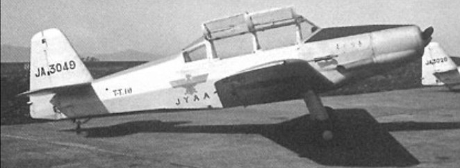
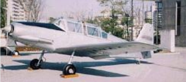
The fuselage of the T-T.10 is fabric covered over a welded chrome-molybdenum steel frame. The engine is a 140 hp (104 kW) Lycoming O-290-D2 flat four, driving a two bladed propeller. Student and instructor sit in tandem with dual controls under a multi-framed, continuous, two part sliding canopy. The rear fuselage line is raised compared with the forward section, but not to the full canopy height. The T-T.10 has conventional landing gear, with narrowly faired cantilever, coil spring damped mainlegs and a tailwheel.
The first T-T.10, registration JA3026, flew for the first time on 30 December 1952; the first production model (JA3049) followed soon after, on 11 February 1953. Production numbers are not known exactly; one report speaks of a “small batch” but only the first two T-T.10s appear in the single engine serial range JA3001 – JA3100, which covers the period August 1952 to September 1955, so they may constitute the whole batch.
One aircraft is on display at the Tokyo Metropolitan College F.A.M.E. Gallery: T-T.10 JA3026.
Engine: Lycoming O-290-D2, 100 kW (140 hp)
Propeller: 2-bladed Sensenich CSM3FM4/C374 fixed pitch
Wingspan: 8.60 m (28 ft 3 in)
Length: 7.15 m (23 ft 5 in)
Height: 2.10 m (6 ft 11 in) tail down
Wing area: 12.0 sq.m (129 sq ft)
Aspect ratio: 6.0
Airfoil: NACA 1415 at root, 2410 (modified) tip
Empty weight: 568 kg (1,252 lb)
Gross weight: 800 kg (1,764 lb)
Fuel capacity: 90 L (19.8 Imp gal; 23.8 US gal)
Maximum speed: 235 km/h (146 mph; 127 kn) at sea level
Cruising speed: 190 km/h (118 mph; 103 kn)
Stall speed: 80 km/h (50 mph; 43 kn) with 30° flaps
Service ceiling: 4,300 m (14,108 ft) service
Rate of climb: 3.8 m/s (750 ft/min) initial
Wing loading: 67 kg/sq.m (14 lb/sq ft)
Power/mass: 8.0 kg/kW (13.1 lb/hp)
Take-off distance to clear 15.25 m (50 ft): 290 m (950 ft)
Landing distance from 15.25 m (50 ft): 300 m (985 ft)
Crew: 2
